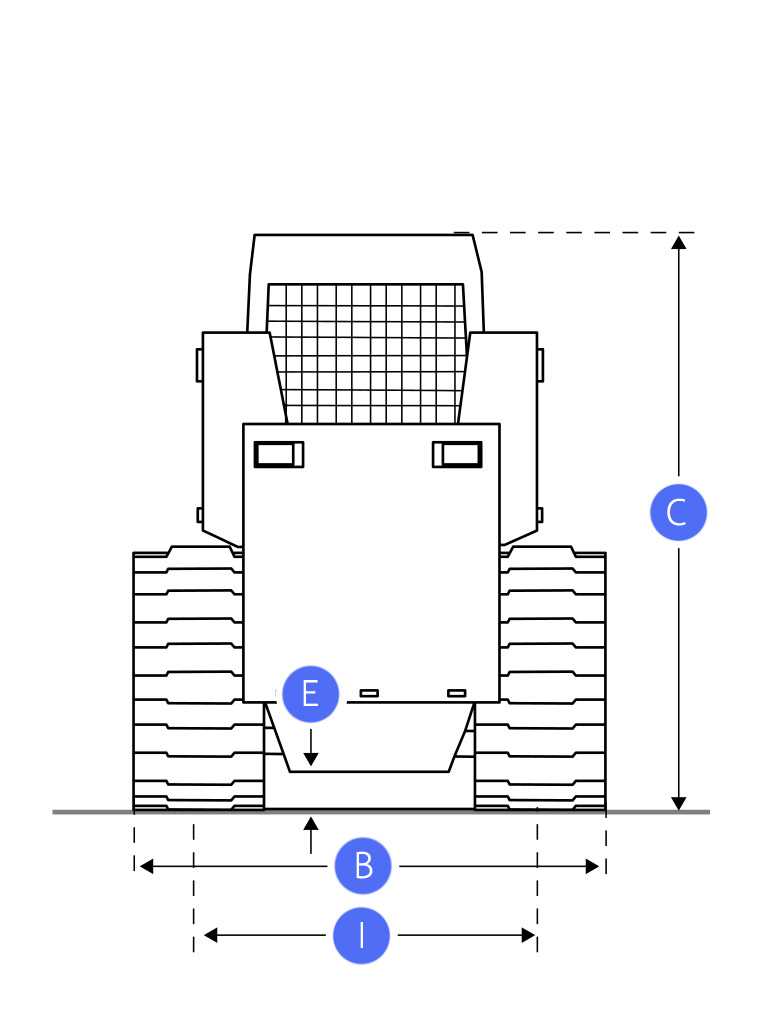
John Deere CT332 Parts Overview
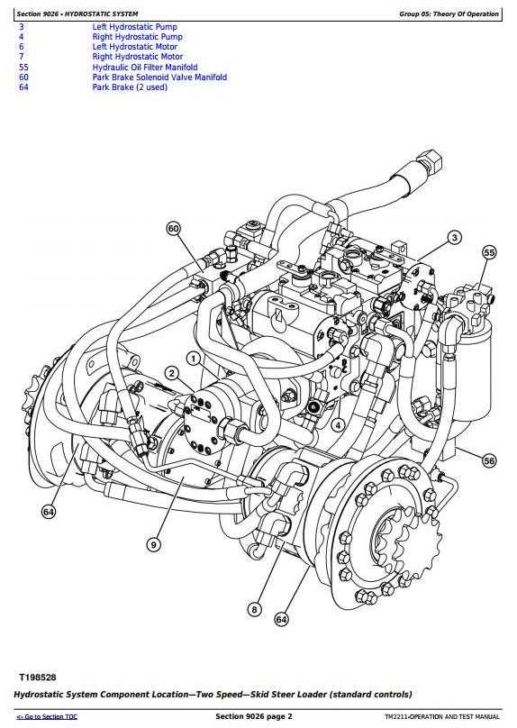
john deere ct332 parts diagram

When working with heavy machinery, having a clear view of the internal configuration is crucial for maintenance and repairs. Knowing the structure and placement of various elements can help streamline tasks, minimize downtime, and enhance operational efficiency. This section aims to provide an overview of key components and their interconnections, allowing for a better understanding of the overall system.

Each machine is made up of numerous essential parts that work together to ensure proper functionality. Recognizing how these elements are linked and where they are located can simplify troubleshooting and repair processes. It also enables operators to identify potential issues before they become major problems.

Regular upkeep involves not only routine checks but also the replacement of worn-out or damaged elements. A comprehensive view of the system layout can significantly assist in identifying the right components, ensuring that maintenance is carried out effectively and safely.

Understanding the John Deere CT332 Diagram

Exploring the illustration of this machinery can provide valuable insights into its structure and functionality. By breaking down the image, one can gain a clearer understanding of how the different elements connect and work together. The visual representation helps to simplify the process of identifying specific components, which can be crucial for maintaining and troubleshooting.

Key Sections of the Illustration

The visual guide is typically divided into several sections, each representing different areas of the equipment. These segments allow users to quickly locate the necessary details and understand the placement of various elements. The layout often includes numbered labels or annotations that correspond to specific items within the image, making it easier to follow along.

Benefits of Using a Diagram

Utilizing an illustration not only saves time but also aids in avoiding errors during maintenance or repairs. It acts as a step-by-step map, providing a detailed overview of how the elements fit together. This can be especially useful for individuals who may not be familiar with the internal workings of the machine.

Section Description
Engine Assembly Shows the layout of the power unit and connected components

Key Components of the CT332

Understanding the primary elements of this heavy machinery is essential for efficient operation and maintenance. Each component plays a crucial role in ensuring smooth functionality and optimal performance, making it vital to recognize the purpose and function of various mechanical and hydraulic systems.

Engine System: The power source drives all essential operations, offering the strength needed to tackle challenging tasks. Its robust design ensures reliability under demanding conditions.

Hydraulic Circuit: Responsible for transferring energy to different parts, this system allows precise control over movements and attachments. It includes various valves, pumps, and hoses that work together to manage fluid flow and pressure.

Track Assembly: Provides stability and traction, enabling the machine to navigate diverse terrains. The assembly includes rollers, sprockets, and rubber tracks, which together ensure a secure grip on various surfaces.

Operator’s Cab: The control center where all commands are executed. It features a user-friendly layout with essential controls and displays for monitoring system performance and adjusting settings as needed.

Cooling System: Maintains the optimal operating temperature by circulating coolant and reducing heat buildup. The system’s radiators, fans, and hoses work together to prevent overheating during prolonged use.

Common Replacement Parts for Maintenance

john deere ct332 parts diagram

Regular upkeep of heavy machinery requires the timely replacement of certain key components. These elements help ensure the equipment operates efficiently and remains reliable in demanding conditions. Understanding which components may need attention during routine maintenance can significantly extend the service life of the machine and prevent unexpected downtime.

Engine and Cooling System Components

The engine, being the heart of the equipment, often demands special attention. Filters such as air, oil, and fuel filters are crucial for maintaining engine cleanliness and performance. Additionally, coolant hoses and radiators should be inspected regularly, as they play a vital role in preventing overheating and ensuring the engine runs smoothly.

Wearable Parts and Hydraulics

Parts that experience constant movement and friction, like belts and seals, are subject to wear and should be checked frequently. The hydraulic system also requires regular maintenance, including replacing hydraulic filters and inspecting lines for potential leaks, to maintain optimal fluid pressure and functionality.

Hydraulic System Overview and Functions

The hydraulic system plays a crucial role in providing power for various functions, utilizing fluid pressure to transmit force efficiently. Understanding how this system operates helps in maintaining performance and diagnosing potential issues. This section covers the essential aspects of the hydraulic components and their primary roles.

Main Hydraulic Components

The hydraulic system consists of several key elements, each contributing to fluid control and pressure management. These components work together to ensure smooth operation and efficient energy transfer.

  • Pumps: Generate the necessary fluid flow and pressure to power different mechanisms. They are the driving force behind hydraulic operations.
  • Valves: Control the flow of hydraulic fluid, directing it to specific areas where power is needed. They play a pivotal role in regulating system performance.
  • Actuators: Convert the hydraulic energy into mechanical

    Engine Parts and Their Roles

    Understanding the various components within an engine and how they work together is essential for ensuring smooth operation and maintenance. Each component plays a crucial role in the overall functioning of the machine, contributing to power generation, energy transfer, and stability. Here, we will explore some of the key elements and their purposes, providing a clearer picture of what keeps the engine running efficiently.

    Primary Components

    The cylinder block serves as the foundation, housing the cylinders where combustion occurs. Within each cylinder, pistons move up and down, converting fuel combustion into mechanical power. The crankshaft, connected to the pistons, transforms this motion into rotational energy that drives other parts of the machine.

    Supporting Elements

    To maintain proper engine temperature, the cooling system circulates coolant, preventing overheating. Additionally

    Track System Structure and Design

    The track system of a compact construction machine plays a crucial role in its performance and efficiency. This design not only provides enhanced stability but also facilitates superior traction, enabling the equipment to navigate various terrains effectively. Understanding the elements that constitute this mechanism is vital for optimizing its functionality and maintenance.

    Key Components of the Track System

    The track system consists of several essential components, each contributing to its overall performance. The following table outlines the primary parts and their functions:

    Component Description
    Track Links Interconnected pieces forming the continuous loop of the track.
    Sprockets Wheels that engage with the track links to provide motion.
    Idlers Components that help guide the track and maintain tension.
    Rollers Bearings that support the weight of the machine and reduce friction.

    Design Considerations

    When designing a track system, several factors must be considered to ensure optimal performance. These include the choice of materials, the geometry of the components, and the overall weight distribution. Each element must work in harmony to provide the desired durability and efficiency in varying working conditions.

    Electrical Components and Wiring Layout

    This section focuses on the essential elements and configurations associated with the electrical system of the machinery. Understanding the arrangement and functionality of these components is crucial for ensuring optimal performance and efficient troubleshooting.

    The electrical assembly includes various parts such as batteries, fuses, and relays, each serving specific roles within the system. The correct installation and maintenance of these components contribute significantly to the reliability and safety of the equipment.

    Additionally, a clear understanding of the wiring layout is vital for identifying connections and potential issues. An organized diagrammatic representation of the wiring can greatly aid in diagnosing electrical faults, making repairs more manageable and efficient.

    Properly mapping out the electrical connections not only enhances operational effectiveness but also assists in future upgrades or modifications. By adhering to established configurations, operators can maintain the integrity of the electrical system, ensuring a seamless workflow.

    Cooling System Parts and Functions

    The cooling system is crucial for maintaining optimal operating temperatures in machinery. It plays a significant role in preventing overheating, ensuring the engine runs efficiently and effectively. Understanding the components involved in this system can help users troubleshoot issues and perform maintenance more effectively.

    Key elements of the cooling mechanism include the radiator, water pump, and thermostat. The radiator dissipates heat absorbed from the engine coolant, allowing for temperature regulation. The water pump circulates coolant throughout the engine and radiator, maintaining a steady flow to prevent hot spots. Additionally, the thermostat monitors and controls the coolant temperature, opening or closing to regulate flow based on the engine’s needs.

    Regular inspection and maintenance of these components are essential for optimal performance. Signs of malfunction may include unusual temperature readings or leaks, which could indicate the need for replacement or repair. By understanding the functions of each part, operators can ensure the longevity and reliability of their equipment.

    Loader Arm and Bucket Assembly Details

    The loader arm and bucket assembly play a crucial role in enhancing the efficiency of material handling tasks. Understanding the components involved in this assembly can significantly improve maintenance and operational practices.

    This section outlines the key elements and their functions within the loader arm and bucket setup:

    • Loader Arm: The primary structure that connects the bucket to the machine. It is designed to lift, lower, and tilt the bucket for various tasks.
    • Bucket: A vital component used for scooping, carrying, and dumping materials. Its design may vary based on the specific application, such as dirt, gravel, or debris handling.
    • Hydraulic Cylinders: These components provide the necessary force to move the loader arm and bucket. They convert hydraulic pressure into mechanical energy, enabling precise control over movements.
    • Pivot Points: These joints allow the loader arm to articulate, facilitating a range of motion. Proper lubrication and maintenance of pivot points are essential for optimal performance.
    • Linkage Mechanisms: These systems connect the loader arm to the hydraulic cylinders and bucket, ensuring efficient transfer of forces and movements.

    Regular inspection and maintenance of these components are essential to ensure smooth operation and longevity of the loader arm and bucket assembly. By understanding the details of this assembly, operators can enhance their skills and effectively manage equipment performance.

    Fuel System Components and Diagram

    john deere ct332 parts diagram

    The fuel system plays a crucial role in the efficient operation of any machinery. It ensures that the engine receives a consistent supply of fuel, facilitating optimal performance and longevity. Understanding the various components and their arrangement can aid in troubleshooting and maintenance.

    Essential Elements of the Fuel System

    This system comprises several key components that work together to transport and manage fuel effectively. These parts include the fuel tank, pump, filter, injectors, and lines, each contributing to the overall functionality and reliability of the engine.

    Component Overview

    Component Description
    Fuel Tank Holds the fuel supply for the engine.
    Fuel Pump Moves fuel from the tank to the engine.
    Fuel Filter Removes impurities and debris from the fuel.
    Fuel Injectors Sprays fuel into the engine for combustion.
    Fuel Lines Connects the various components, facilitating fuel flow.

    Understanding the Control Panel Layout

    The control panel of a machine serves as the central hub for managing its functions and operations. Familiarity with this layout is crucial for efficient and safe usage. Each button, switch, and indicator light plays a significant role in controlling various aspects of the equipment.

    In general, the control panel is designed to provide operators with easy access to essential controls. Understanding the placement and purpose of each element can enhance user experience and prevent operational errors. The following table outlines common features found on control panels, along with their respective functions.

    Control Element Function
    Power Switch Turns the machine on or off
    Throttle Control Regulates engine speed
    Indicator Lights Displays machine status or alerts
    Control Joystick Manages movement and operations
    Emergency Stop Button Immediately halts all functions