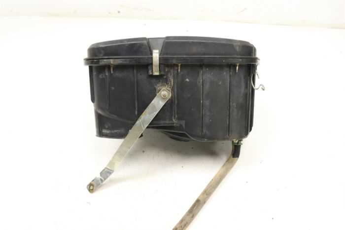
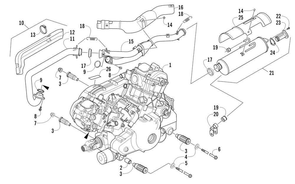
Parts Diagram for 2012 Arctic Cat Wildcat 1000

The intricate setup of vehicle systems requires a clear comprehension of their layout and interconnections. By exploring the arrangement of different components, you can gain insights into how each element functions together to ensure optimal performance and reliability in demanding terrains.
In this section, we delve into the essential details of mechanical assemblies used in high-performance off-road machines. The focus will be on recognizing the strategic placement and interaction of various modules, helping enthusiasts and mechanics alike to enhance their maintenance and repair skills.
Precision in assembly and arrangement is crucial to achieving peak efficiency and durability. Our approach emphasizes a thorough analysis of these configurations, enabling a deeper understanding of each system’s role in the vehicle’s overall operation. Whether you’re troubleshooting issues or upgrading parts, knowing the exact positioning and alignment of each element is vital for successful execution.
The cooling system in any performance-focused vehicle plays a vital role in maintaining optimal engine temperature. This setup is designed to prevent overheating, ensuring that the engine components function efficiently under various conditions. Understanding the core elements of this mechanism is crucial for enhancing performance and longevity.
Main Components Overview
The primary components of the cooling system are carefully engineered to work together, dissipating heat generated during operation. Each element has a specific function that contributes to the overall balance of temperature regulation.
- Radiator: Acts as the central hub for transferring heat away from the engine, using air to cool the liquid circulating through the system.
- Thermostat: Monitors engine temperature and regulates the flow of coolant to maintain a consistent level of warmth.
- Water Pump: Circulates the coolant through the system, ensuring that it reaches all areas that require
Understanding Suspension Assembly Design
The suspension system is a crucial component that plays a vital role in the overall performance and stability of off-road vehicles. This section explores the fundamental principles behind its construction, focusing on how each element contributes to a smoother ride and enhanced control. By examining the interaction of individual elements, one can gain a clearer insight into the engineering that ensures maximum traction and adaptability on diverse terrains.
Core Components and Their Roles
At the heart of the suspension design are key components like shocks, springs, and linkages, each fulfilling a distinct function in maintaining vehicle balance and handling. Shock absorbers play a significant role in reducing vibrations and impacts from uneven surfaces, while springs ensure that the chassis remains stable during acceleration and braking. These components work in harmony to manage energy transfer, which is essential for achieving a controlled driving experience.
Detailed View of Shock Absorber Placement
In this section, we will explore the arrangement and positioning of the damping components within the suspension system. Understanding their alignment and specific roles is crucial for ensuring optimal performance and stability during various driving conditions.
- Front Alignment: The damping units in the front section are strategically positioned to provide maximum control during maneuvers. Their mounting angles are designed to absorb impact efficiently, enhancing the smoothness of the ride.
- Rear Configuration: The rear damping elements are installed with a focus on maintaining balance and reducing vibrations. Their placement supports the vehicle’s load distribution, ensuring consistent traction on uneven surfaces.
- Adjustment Points: Multiple adjustment points allow for fine-tuning the damping force. This flexibility enables modifications based on terrain requirements, providing adaptability for both rough trails and smoother paths.
Careful consideration of the shock absorbers’ positions
Brake System Configuration Guide
The arrangement and functionality of the braking setup play a crucial role in ensuring the vehicle’s overall performance and safety. Understanding the various components and their interactions can help in maintaining the system’s efficiency and responsiveness. This guide will outline the core elements of the braking configuration, focusing on their roles within the system.
Component Description Master Cylinder The heart of the braking mechanism, responsible for converting pedal pressure into hydraulic force, which activates the brakes. Brake Calipers Devices that apply pressure to the brake pads, pressing them against the rotors to slow down or stop the motion of the wheels. Brake Pads Friction materials that come into contact with the rotors to generate the necessary force for deceleration. Visual Breakdown of Brake Line Routing
The layout of the brake system plays a crucial role in ensuring efficient performance and safety. By examining the specific path and connections, it becomes easier to identify potential areas for maintenance and upgrades.
Key Components in the System
The brake line configuration consists of various sections that connect different elements of the braking mechanism. Understanding how these parts interlink helps in both troubleshooting and optimizing the setup for better control and responsiveness.
Detailed Layout Overview
Component Description Function Master Cylinder Central hub where the brake fluid is pressurized. Initiates the hydraulic force that activates the brake lines. Front Brake Lines Electrical Wiring Arrangement Overview
The organization of wiring in a vehicle’s system is crucial for maintaining a reliable and efficient flow of electrical energy to various components. A well-structured layout helps prevent malfunctions and ensures that each element receives the power it requires to function optimally. Understanding the connections and pathways within this setup is essential for both maintenance and upgrades.
Main Connection Points
The electrical structure typically begins at a central power source, branching out to various sections that control specific functions. These main junctions serve as distribution hubs, directing energy to key areas like the ignition, lighting, and accessory modules.
- Power Distribution: This section ro
Highlighting Key Connectors and Terminals

Understanding the arrangement and placement of essential links and junctions is crucial for ensuring optimal performance. These elements play a significant role in the functionality of any system, acting as critical points of connection that facilitate the smooth flow of power and communication.
Primary Link Points
At the core of this setup, certain link points serve as the backbone for electrical distribution. Identifying these nodes allows for efficient maintenance and troubleshooting, enhancing the overall reliability of the unit.
Detailed Connection Overview
The following table provides a comprehensive look at some of the most important terminals, highlighting their roles and associated tasks:
Connector Function Location Junction A Power dis Transmission System Schematic Analysis
This section delves into the intricate workings of the power transfer mechanism, highlighting its essential components and functionality. Understanding the arrangement and interrelation of these elements is crucial for effective maintenance and troubleshooting.
The transmission system plays a pivotal role in the overall performance of the vehicle, ensuring optimal power delivery from the engine to the wheels. The schematic representation illustrates how various parts work in unison to facilitate smooth operation.
Component Description Gearbox Regulates gear ratios to optimize engine performance for different speeds. Clutch Assembly Engages and disengages the engine from the transmission to allow for smooth shifting. Drive Belt Transfers power from the engine to the transmission and aids in torque management. Transmission Fluid Lubricates components, providing cooling and ensuring smooth operation. Torque Converter Facilitates the transfer of engine power to the drivetrain, allowing for seamless acceleration. By analyzing the schematic, one can identify potential issues and understand the impact of each component on the system’s efficiency. Regular examination and maintenance of these parts are vital for prolonging the lifespan of the vehicle.
Arrangement of Gear and Clutch Components
The organization of transmission and drive elements is crucial for optimal performance and reliability in off-road vehicles. A well-designed assembly ensures efficient power transfer from the engine to the wheels, enhancing acceleration and maneuverability.
Within this assembly, various gears and clutches play a pivotal role. The gears are strategically positioned to facilitate smooth shifting and maintain torque delivery. Clutches serve as key interfaces, allowing for controlled engagement and disengagement, which is essential for managing power flow during different driving conditions.
Additionally, the arrangement must consider factors such as durability and heat dissipation. Components are typically arranged to minimize friction and wear, while also providing adequate space for heat management. This thoughtful configuration enhances the longevity of the system and contributes to the overall driving experience.
Body Panel Mount
The body panel mounting system is essential for ensuring the structural integrity and aesthetics of off-road vehicles. It involves various components designed to securely attach panels to the chassis, providing stability and protection against external elements.
Components of the Mounting System
- Brackets: These are metal supports that hold the panels in place, ensuring a firm attachment.
- Fasteners: Screws, bolts, and clips that secure the brackets and panels together.
- Grommets: Rubber inserts that prevent vibration and reduce wear on the panels.
- Sealants: Materials used to enhance water resistance and prevent debris from entering.
Installation Process
- Begin by aligning the body panels with the designated mounting points on the chassis.
- Attach brackets using the appropriate fasteners, ensuring they are tightened to specifications.
- Insert grommets in any necessary locations to absorb shock and vibration.
- Apply sealants to the edges of the panels for additional protection against the elements.