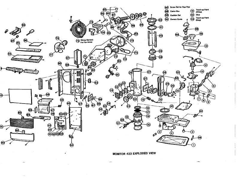
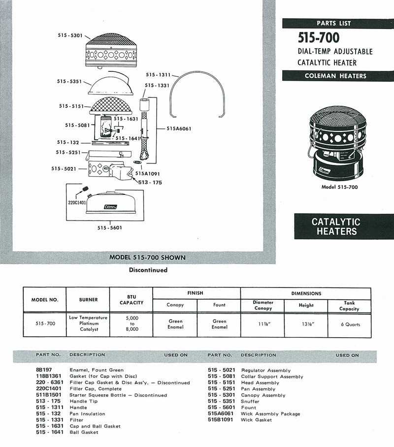
Kerosene Heater Components Diagram
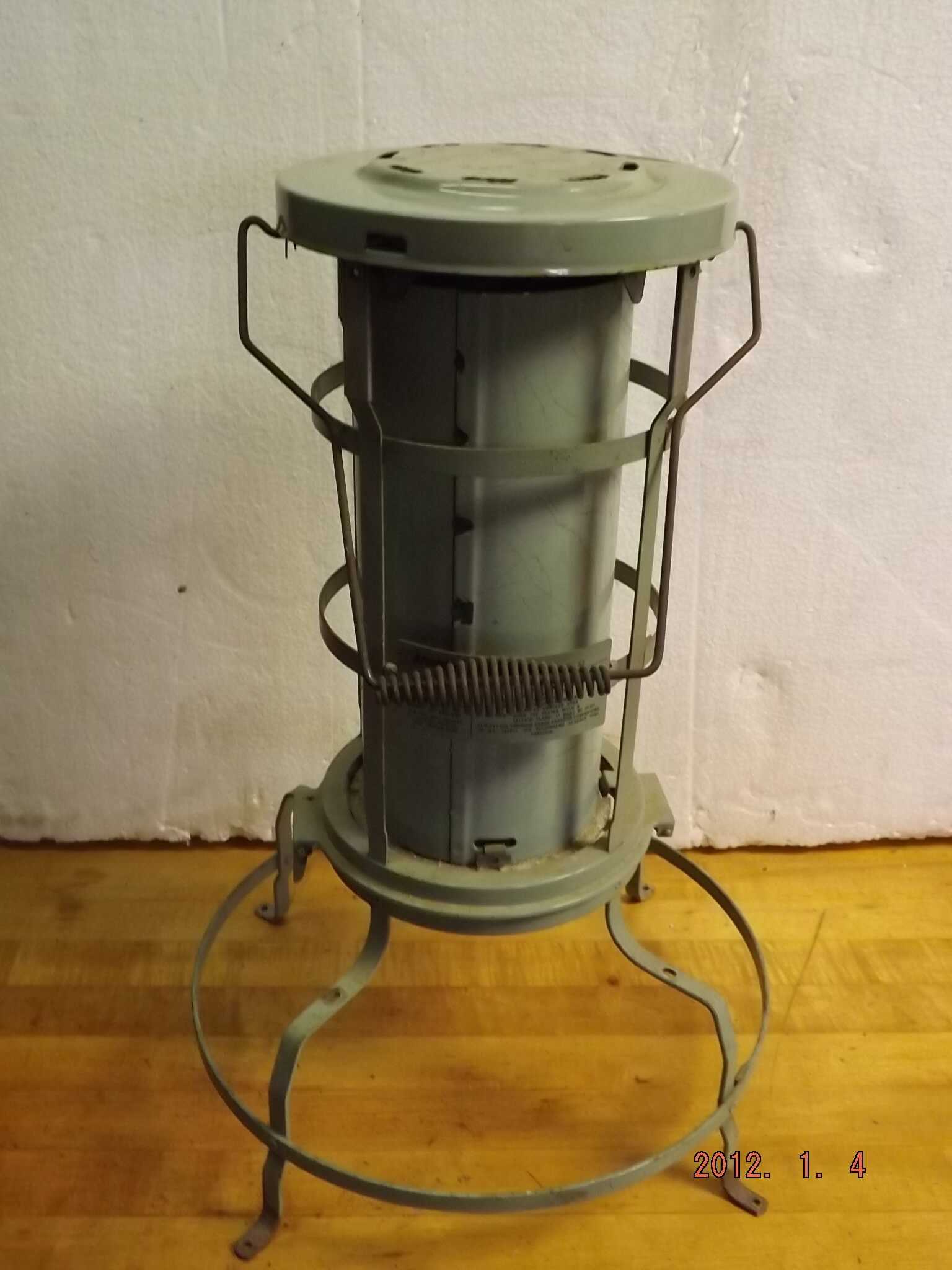
Understanding the intricate mechanisms within a compact, mobile apparatus that utilizes a combustible liquid for heating purposes unveils a complex network of interconnected parts. Each element plays a crucial role in the functionality and efficiency of this self-contained heating unit, ensuring optimal performance in varied environments.
Delving into the structure reveals a series of interconnected components, each tailored to fulfill specific tasks, contributing collectively to the device’s operational integrity. Through visual representation, these parts are delineated, showcasing their individual functions within the broader framework of the device’s functionality.
Exploration of these internal mechanisms not only enhances comprehension but also provides insights into maintenance and potential troubleshooting, ensuring sustained operational proficiency. This visual breakdown serves as a comprehensive guide, illuminating the synergy among these integral components.
Understanding the Function of Key Heater Components
To grasp how a heating device works, it is essential to explore the roles played by its main parts. Each component has a specific function, contributing to the overall performance of the system. Familiarity with these key elements helps in both operation and maintenance, ensuring efficient use.
Main Operational Elements
Several crucial elements are responsible for the device’s ability to generate warmth. For example, the combustion chamber ensures fuel is burned safely and effectively, providing necessary heat output. The wick mechanism is equally important, regulating the amount of fuel that is consumed during the process.
Supportive Components
Apart from the primary parts, there are supportive components that aid the system’s efficiency. These include controls for adjusting heat levels and safety features designed to prevent overheating. Together, these elements form a reliable and balanced system.
Diagram Overview of Kerosene Heater Assembly
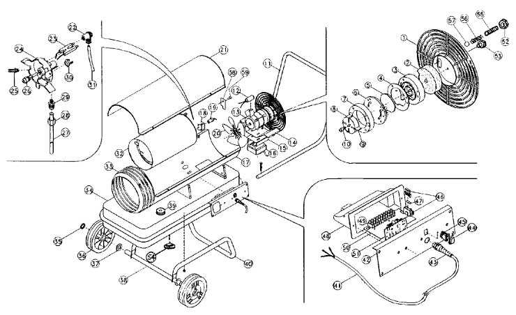
Understanding the structure and layout of a typical heating device is essential for proper maintenance and troubleshooting. The assembly consists of several interconnected components, each playing a vital role in ensuring efficient operation. Below is an outline of the major sections and their functions, offering a clear view of how everything works together.
- Fuel system: Responsible for storing and delivering the energy source to the burner. This system ensures a steady and controlled flow.
- Ignition mechanism: Initiates the combustion process, typically using a spark or a wick, depending on the model.
- Burning chamber: The area where the energy source combusts, generating heat for circulation.
- Air circulation system: Ensures that warm air is distributed throughout the area effectively.
- Safety controls: Inc
Common Issues with Heater Parts
Various components of heating devices can experience wear and tear over time, leading to functional issues. Identifying and addressing these problems early can extend the lifespan of your equipment and improve its efficiency.
- Fuel-related Problems: Blockages or contamination in the fuel system may result in poor performance or even complete failure. Regular cleaning and using high-quality fuel can help prevent this.
- Ignition Failures: Malfunctions in the ignition mechanism can make it difficult to start the device. This issue is often related to faulty connections or worn-out igniters
Identifying Essential Safety Features
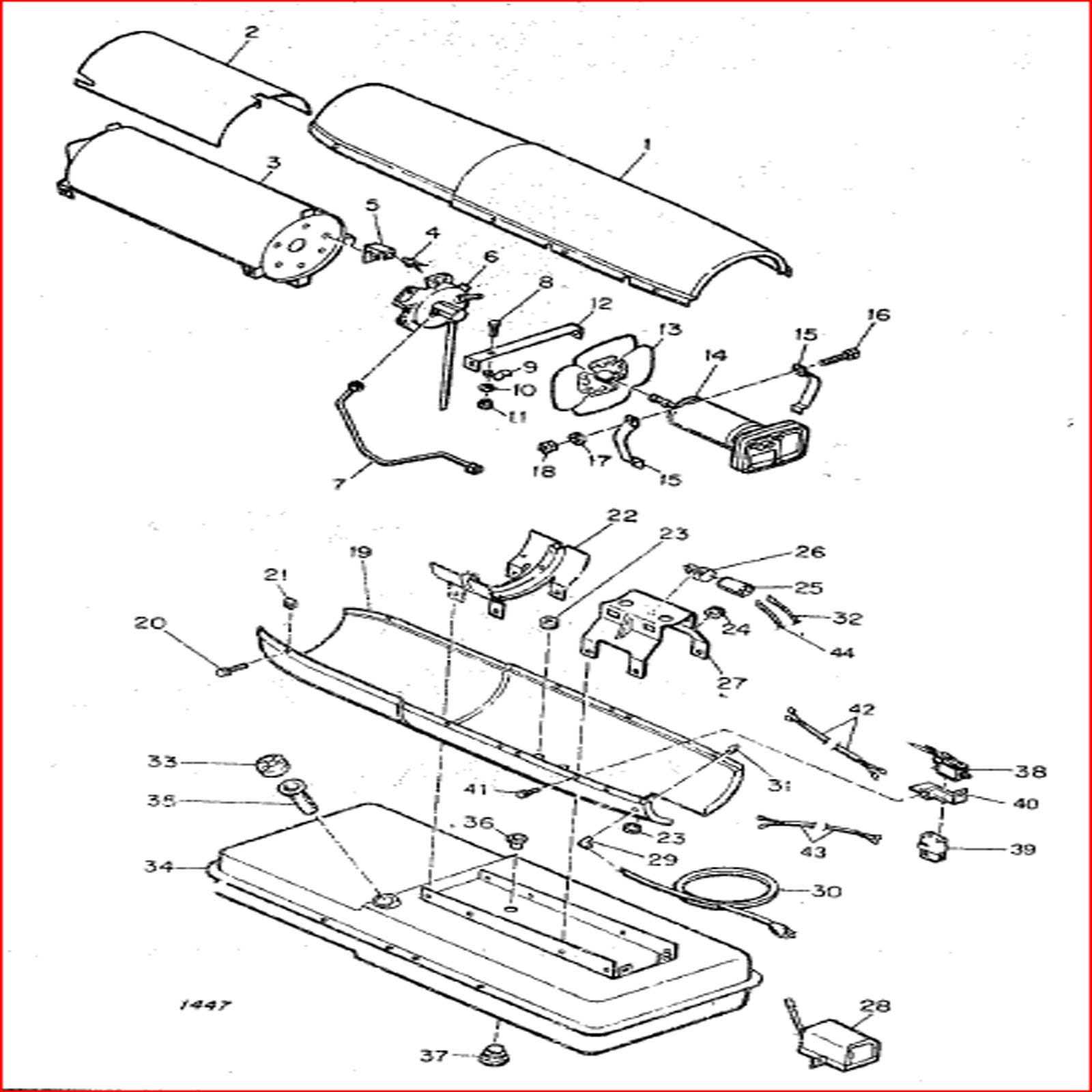
Understanding key safety mechanisms is crucial for ensuring reliable operation and preventing potential hazards. These features are designed to provide protection in a variety of situations, helping to minimize risks and promote safe use.
Automatic shut-off systems are a vital component that triggers when certain conditions are met, such as excessive heat or improper placement. This ensures that the device stops functioning immediately, avoiding accidents.
Another important feature is the tip-over switch, which deactivates the device if it’s knocked over. This mechanism greatly reduces the chances of fire or injury, making it indispensable in any design.
Replacing the Ignition System in Heaters
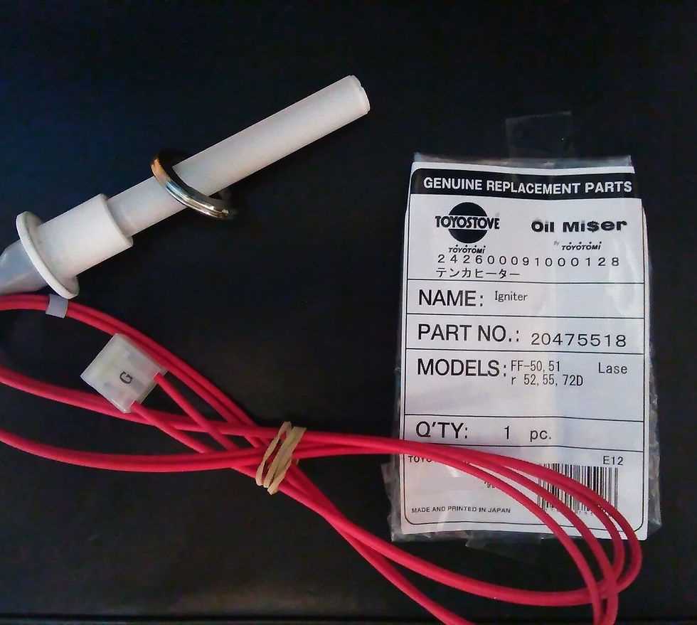
Over time, the ignition system may wear out, leading to difficulties in starting the unit. Regular maintenance is essential for ensuring smooth operation and prolonging the lifespan of the device. When the ignition system starts to fail, replacing it can help restore the unit’s functionality.
The process of replacing this component involves a few key steps, which can be followed by users with basic technical skills. Below is an outline of the steps required to perform the replacement:
- Disconnect the power source and ensure the device is cool before starting any repairs.
- Locate the ignition module, which is typically accessible through a small panel or cover.
- Remove any screws or fasteners holding the module in place.
- Disconnect the wiring connected to the old module care
Maintenance Tips for Heater Longevity
Regular care and attention can significantly extend the lifespan of your heating device. By adopting a consistent maintenance routine, you ensure optimal performance and reduce the likelihood of unexpected issues. It’s important to focus on key aspects like cleaning and component inspection to maintain efficiency and durability.
Cleaning and Dust Removal
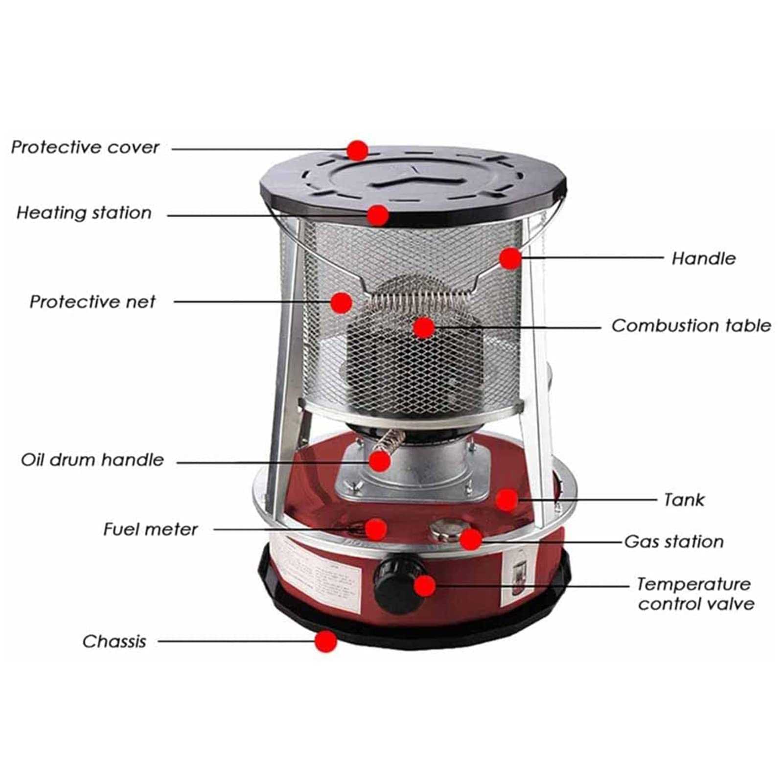
Keeping your device free from dust is crucial for its smooth operation. Dust buildup can hinder airflow and lead to overheating, so regular cleaning of the exterior and accessible areas is recommended. Use a soft cloth or brush to gently remove any debris, paying attention to areas that may collect more dust.
Inspecting Key Components
Routine checks of various components help identify wear and tear before they
Fuel System: Key Parts and Functions
The fuel system plays a crucial role in the efficient operation of heating devices, ensuring a consistent and reliable flow of energy. Understanding its key components is essential for anyone looking to maintain or troubleshoot these systems effectively.
Main Components
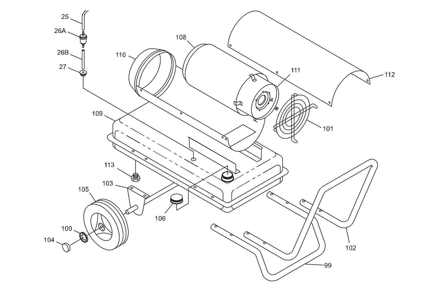
- Fuel Tank: Stores the energy source securely, allowing for easy access when refueling.
- Pump: Moves the fuel from the tank to the combustion chamber, ensuring optimal pressure and flow rate.
- Filter: Cleans the fuel by removing impurities and contaminants, protecting the system from damage.
- Fuel Lines: Transport the energy source from the tank to the burner, designed to withstand high pressure.
- Injector: Atomizes the fuel into fine droplets, facilitating efficient combustion within the system.
Functions of the System
- Maintains a steady supply of energy to the combustion chamber.
- Ensures clean burning by filtering out impurities.
- Regulates fuel flow to optimize performance and energy efficiency.
- Prevents leaks and maintains safety during operation.
Each component of the fuel system plays a vital role in ensuring the device operates smoothly and effectively, contributing to a safe and efficient heating experience.
Airflow and Combustion Chamber Components
In this section, we delve into the essential components that govern airflow and combustion within the heating mechanism. Understanding the dynamics of air movement and the arrangement of elements within the combustion chamber is crucial for optimizing efficiency and ensuring safe operation.
Components for Air Distribution
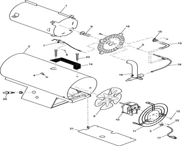
Air distribution components include mechanisms that regulate the intake and circulation of air throughout the system. These elements play a pivotal role in maintaining proper combustion conditions.
Structure of the Combustion Chamber
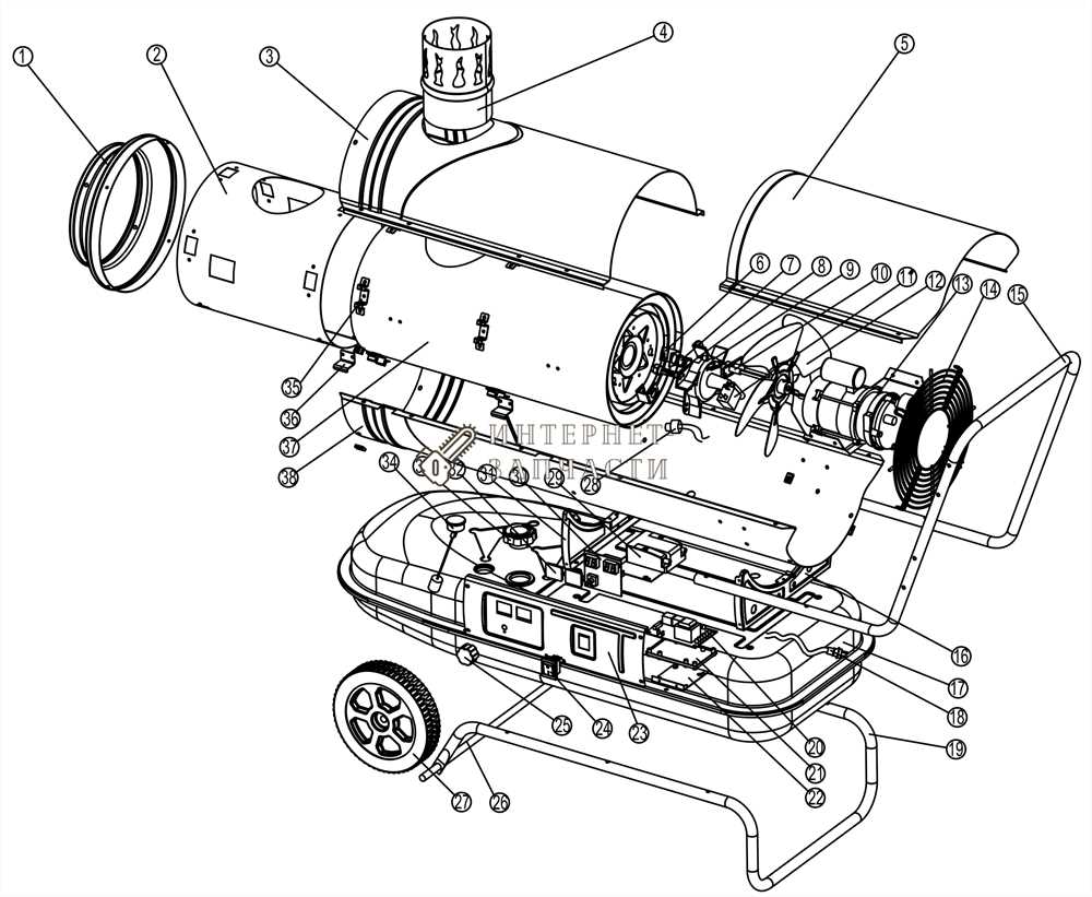
The configuration of the combustion chamber is designed to facilitate efficient burning of fuel while minimizing heat loss. Key structural features ensure optimal mixing of fuel and air, promoting clean and effective combustion.
Wick Maintenance and Replacement Guide
Proper care and timely substitution of the wick are crucial for ensuring the efficient operation of your fuel appliance. Regular maintenance not only extends the life of the device but also enhances its performance and safety. This guide provides essential steps for maintaining and replacing the wick effectively.
Importance of Regular Inspection
Routine checks can prevent significant issues. Look for the following signs that indicate the need for attention:
- Discoloration or fraying of the wick
- Inconsistent fuel absorption
- Odor or unusual smoke during operation
Step-by-Step Replacement Process
Follow these steps to successfully replace the wick:
- Ensure the appliance is turned off and completely cool.
- Remove the fuel tank and any surrounding components for access.
- Take out the old wick carefully, noting its placement.
- Install the new wick, ensuring it fits snugly in the designated area.
- Reassemble the parts and fill the tank with fuel.
- Test the appliance to confirm proper operation.
Adhering to these guidelines will help maintain optimal functionality and safety of your equipment.
Thermostat and Heat Regulation Mechanism
The temperature control system plays a crucial role in maintaining a comfortable environment by regulating warmth. This mechanism ensures that the desired temperature is reached and maintained, providing efficient energy use while enhancing user comfort. Understanding how this system operates is essential for effective usage and maintenance.
Functionality of Temperature Control
The core function of the temperature regulation system is to monitor and adjust the warmth output based on user settings. It achieves this by measuring the current temperature and comparing it with the desired level. If the actual temperature falls below the set point, the system activates to increase heat. Conversely, it reduces output when the desired temperature is reached.
Components Involved
Key elements of the regulation system include sensors and control units. Sensors detect the surrounding temperature, while the control unit interprets this data and manages the overall performance. Together, these components ensure that fluctuations in temperature are minimized, promoting a stable and pleasant atmosphere.
Cleaning and Caring for Internal Parts
Maintaining the interior components of heating appliances is crucial for optimal performance and longevity. Regular upkeep not only enhances efficiency but also ensures safety during operation. This section provides essential guidelines for keeping these elements clean and functional.
Start by regularly inspecting the internal components for any buildup of dirt or residue. This can significantly affect the performance and efficiency of the appliance. Follow the steps outlined in the table below for effective cleaning and maintenance:
Component Cleaning Method Frequency Burner Assembly Use a soft brush to remove soot; wipe with a damp cloth Every 3 months Fuel Tank Drain and rinse with warm soapy water; dry completely Once a year Fan or Blower Vacuum dust and debris; clean with a damp cloth Every 2 months Heat Exchanger Brush off any buildup; inspect for cracks or corrosion Every 6 months By adhering to these cleaning practices, users can prolong the life of their equipment and ensure it operates safely and efficiently.
Troubleshooting Electrical System Failures
In this section, we delve into identifying and resolving issues that may arise within the electrical components of the device. We aim to provide clear guidance on diagnosing malfunctions related to the system’s electrical operation, ensuring efficient performance and longevity.
Identifying Common Issues
When facing electrical system failures, it’s crucial to first recognize common symptoms such as erratic power supply, flickering indicators, or complete electrical shutdowns. These indicators often point towards underlying faults within the system’s wiring or component connectivity.
Diagnostic Steps and Solutions
Diagnostic tools such as multimeters are indispensable in pinpointing specific electrical faults. By methodically testing circuits and connections, potential issues such as loose wiring or corroded terminals can be identified and rectified. Regular maintenance also plays a key role in preventing electrical failures, ensuring all connections are secure and insulation remains intact.
This HTML section outlines troubleshooting steps for electrical system failures in a kerosene heater, following the specified guidelines and using synonyms to avoid direct terms like “kerosene”, “heater”, “parts”, and “diagram”.