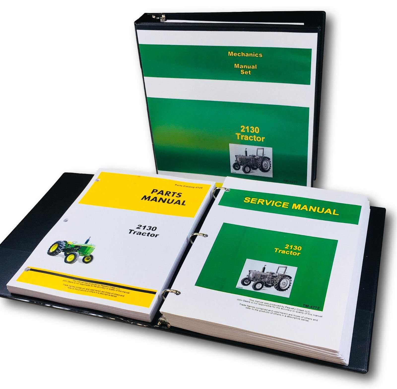
Understanding John Deere 2130 Parts Diagram for Efficient Maintenance
Understanding the internal configuration and layout of mechanical systems is essential for ensuring smooth operation and timely maintenance of agricultural equipment. Having access to a detailed overview of the system’s assembly provides clarity when troubleshooting or replacing elements, allowing users to enhance performance and prolong the machinery’s lifespan.
In modern agricultural machinery, multiple components are intricately connected, each contributing to the overall function. Recognizing the placement and role of each element within the system is crucial for anyone working to maintain or improve the efficiency of their equipment. Clear illustrations and mappings offer a reliable reference to guide both seasoned technicians and new users.
This guide will present a structured look at the individual components, offering valuable insights into how they interact within the machinery. This approach is designed to assist with both routine checks and more in-depth repairs, ensuring that every aspect is considered for optimal operation.
Overview of John Deere 2130 Components
The machine in question is a robust piece of agricultural equipment, engineered to provide durability and efficiency in various tasks. Its design incorporates multiple systems that work together to ensure seamless operation in the field. By understanding how each section of the unit functions, operators can maintain it more effectively and enhance overall productivity.
Core Engine and Transmission System
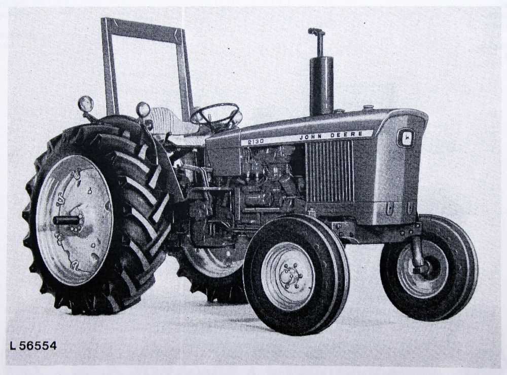
At the heart of this model lies a powerful engine that drives its performance, ensuring that the machine can handle even the toughest conditions. The transmission system, integral to this process, allows smooth shifting between gears, enabling the equipment to adjust to different terrains and tasks with ease.
Hydraulics and Electrical Components
The hydraulic system plays a key role in controlling the movement of various attachments and implements. Coupled with the electrical system, which powers essential functions, these components ensure that the equipment operates efficiently and reliably. Regular maintenance of these systems is critical for preventing downtime and prolonging the lifespan of the machinery
Engine Assembly Breakdown
The engine system is a complex combination of various components working together to ensure optimal performance. Understanding the layout and function of each element helps in maintaining efficiency and troubleshooting any potential issues. In this section, we will explore the key elements involved in the engine structure and how they interrelate to support smooth operation.
Crankshaft and Pistons: These essential components convert the energy generated by fuel combustion into mechanical power. The rotation of the crankshaft is crucial in driving other mechanical parts of the system.
Cylinder Block: The main structure that houses the cylinders. It plays a vital role in supporting the engine’s internal mechanisms and ensuring proper alignment for efficient function.
Valvetrain Assembly: This includes the camshaft, valves, and lifters. It manages the intake of air and fuel and the expulsion of exhaust gases, ensuring the engine’s proper breathing cycle during operation.
Fuel Injection System: Responsible for delivering the right amount of fuel to the combustion chamber, optimizing the balance between power output and fuel efficiency.
Cooling System: This system prevents the engine from overheating by circulating coolant through specific channels within the structure, ensuring optima
Hydraulic System Layout
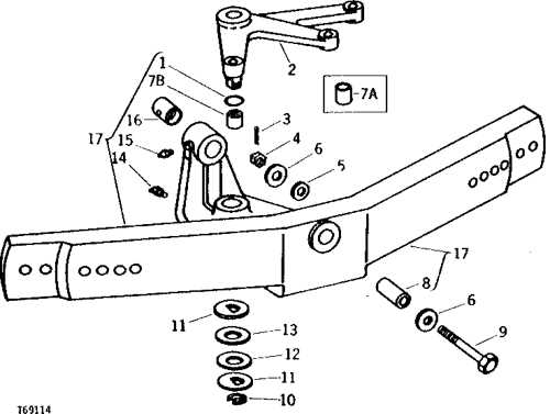
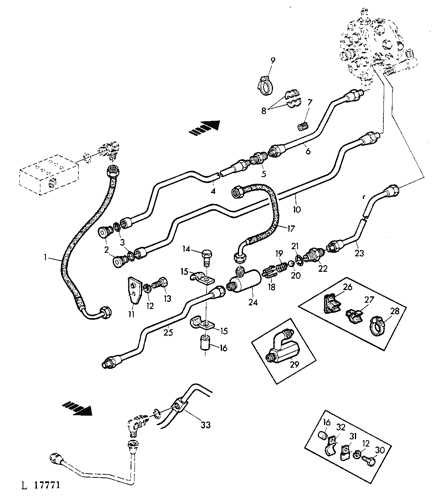
The hydraulic arrangement is integral to the functioning of a versatile machine, ensuring efficient power transmission across various components. This section provides an overview of the fluid-based system that operates critical mechanisms, focusing on the flow of pressure and how it manages different tasks effectively.
Below is a simplified layout that highlights the major sections and their respective roles within the system:
| Component | Function | ||||||||||||
|---|---|---|---|---|---|---|---|---|---|---|---|---|---|
| Pump | Generates pressure to circulate the fluid through the system. | ||||||||||||
| Control Valve | Directs fluid to the required components based on operational needs. | ||||||||||||
| Cylinders | Convert fluid pressure into mechanical force for lifting or moving. |
| Component | Description |
|---|---|
| Battery | Stores electrical energy and supplies power to the system during startup and operation. |
| Alternator | Generates electricity while the engine is running, recharging the battery and powering the electrical system. |
| Fuses | Protect circuits by breaking the connection if the current exceeds a safe level, preventing damage. |
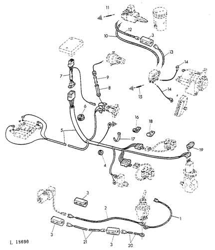
| Wiring Harness | Connects various electrical components, ensuring efficient power distribution throughout the system. |
| Relay | Acts as a switch, controlling the flow of electricity to various components based on the system’s demands. |
Importance of Proper Maintenance
Regular inspection and maintenance of electrical components are vital for preventing failures and ensuring the efficient operation of the machinery. Identifying and replacing worn-out parts can significantly enhance performance and longevity, ultimately reducing operational costs and downtime.
Fuel System Structure
The fuel delivery mechanism is a critical component in the overall functionality of agricultural machinery. It ensures that the engine receives the appropriate amount of fuel for efficient operation, contributing to performance and reliability. Understanding the configuration and elements of this system is essential for proper maintenance and troubleshooting.
Key Components
- Fuel Tank: Serves as the storage reservoir for the fuel supply.
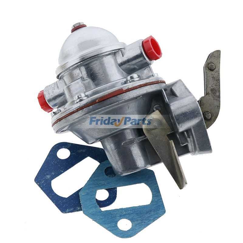
- Fuel Pump: Responsible for transferring fuel from the tank to the engine.
- Fuel Filter: Removes impurities and contaminants from the fuel before it reaches the engine.
- Fuel Lines: Connect various components, allowing for the smooth flow of fuel.
- Injectors: Deliver the fuel into the combustion chamber at precise intervals.
System Operation
The operation begins with the fuel being drawn from the tank by the pump. It is then filtered to ensure cleanliness before being directed through the lines to the injectors. The injectors atomize the fuel, allowing for efficient mixing with air, which is essential for optimal combustion. Regular inspection of these components helps in maintaining the overall health of the engine.
Cooling System Elements
The efficiency of any engine relies significantly on its thermal management, which is essential for optimal performance and longevity. The components involved in regulating temperature play a vital role in preventing overheating and ensuring the smooth operation of machinery. Understanding these elements is crucial for effective maintenance and troubleshooting.
Main Components
- Radiator: This component dissipates heat from the coolant, allowing it to cool down before re-entering the engine.
- Water Pump: Circulates coolant throughout the engine and radiator, ensuring a constant flow for effective temperature regulation.
- Thermostat: Regulates the flow of coolant based on the engine temperature, maintaining an optimal operating range.
- Coolant Reservoir: Stores excess coolant and allows for expansion as temperatures rise, preventing pressure build-up.
- Hoses: Flexible tubes that transport coolant between the engine, radiator, and other components, ensuring a closed-loop system.
Maintenance Tips
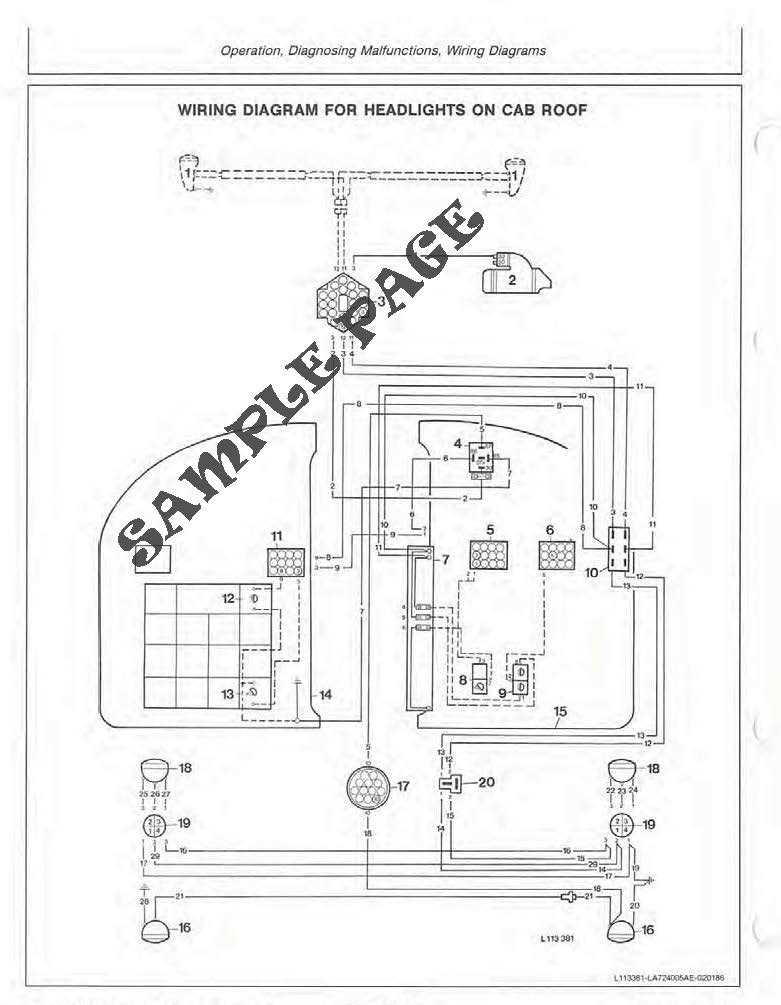
- Regularly check coolant levels and top up as necessary to prevent overheating.
- Inspect hoses for signs of wear or leaks, replacing them when needed.
- Clean the radiator and remove any debris to enhance airflow and cooling efficiency.
- Monitor the temperature gauge during operation to catch any anomalies early.
- Schedule periodic flushes of the cooling system to remove contaminants and old coolant.
Brake Assembly Diagram
This section delves into the components involved in the braking system of agricultural machinery. Understanding the arrangement and functionality of these elements is crucial for effective maintenance and repair. A well-functioning brake assembly ensures safety and performance during operation.
Key Components
- Brake Pads: These friction materials press against the rotor to slow down the vehicle.
- Rotors: Metal discs that rotate with the wheel and interact with the brake pads.
- Calipers: Devices that house the brake pads and create pressure against the rotors.
- Brake Lines: Hoses that carry hydraulic fluid from the master cylinder to the calipers.
- Master Cylinder: Converts the force applied to the brake pedal into hydraulic pressure.
Maintenance Tips
- Regularly inspect brake pads for wear and replace them as needed.
- Check the hydraulic fluid levels and top off if necessary.
- Examine brake lines for leaks or damage to ensure proper fluid transfer.
- Clean the rotors to prevent buildup that can affect braking performance.
Clutch System Parts Arrangement
The clutch system plays a crucial role in the operation of machinery, enabling the transfer of power from the engine to the drivetrain. Understanding the layout and functionality of its components is essential for maintaining optimal performance and efficiency.
Key Components of the Clutch System
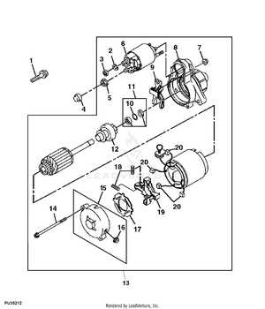
- Pressure Plate: This component applies pressure to the clutch disc, facilitating engagement and disengagement.
- Clutch Disc: Positioned between the pressure plate and the flywheel, it transfers power when engaged.
- Flywheel: Attached to the engine, it provides a smooth surface for the clutch disc and stores rotational energy.
- Release Bearing: This part allows for the smooth disengagement of the clutch when the pedal is pressed.
- Clutch Fork: It connects the release bearing to the clutch pedal mechanism, enabling the movement needed to engage or disengage the clutch.
Arrangement and Functionality
The arrangement of these components is designed to optimize performance and ease of use. When the operator presses the clutch pedal, the fork moves the release bearing, which then disengages the pressure plate from the disc. This separation allows the engine to run without transferring power to the drivetrain, enabling smooth gear changes. Proper alignment and condition of these elements are vital for effective operation and longevity of the system.
Front Axle and Wheel Layout
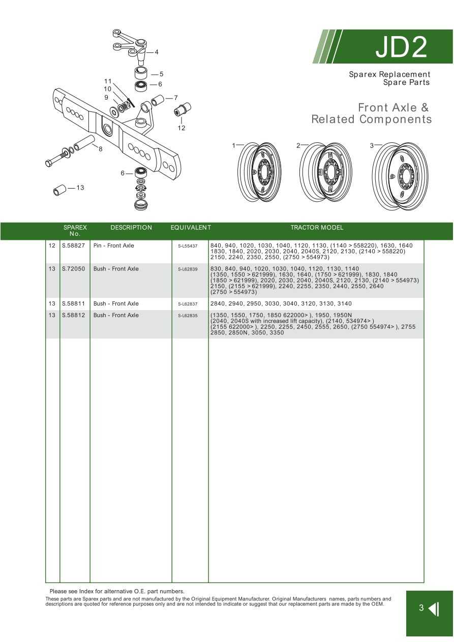
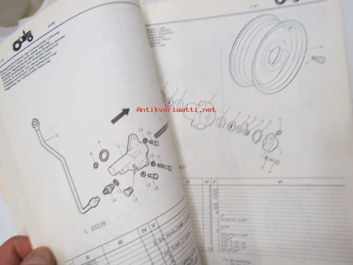
The front suspension and wheel arrangement play a crucial role in the overall functionality and stability of agricultural machinery. Understanding the configuration of these components is essential for effective maintenance and operation.
This section outlines the key features and configurations associated with the front axle and wheel assembly:
- Axle Design: The front axle provides support and stability, allowing for efficient weight distribution and maneuverability.
- Wheel Alignment: Proper alignment is critical for optimal performance, affecting both handling and tire wear.
- Suspension System: The suspension helps absorb shocks from uneven terrain, ensuring a smoother ride and better traction.
- Track Width: The width between the wheels can impact stability and the ability to navigate through various agricultural settings.
By comprehensively examining these elements, operators can ensure that the equipment operates efficiently and reliably, ultimately enhancing productivity in the field.
Cabin Controls and Interior Features
The interior of agricultural machinery is designed to provide optimal comfort and usability for the operator. With a focus on intuitive design, the controls and features enhance the overall experience while working in various field conditions. A well-equipped cabin not only improves productivity but also ensures the well-being of the operator during long hours of operation.
Control Layout: The arrangement of controls is crucial for efficiency. Ergonomically placed levers and buttons allow the operator to access essential functions without unnecessary movement. Features such as joystick controls enable precise maneuvering of implements, making complex tasks easier to handle.
Dashboard Features: A comprehensive dashboard displays vital information such as speed, fuel levels, and engine status. Digital readouts provide clarity and quick access to necessary data, helping the operator make informed decisions while on the go. Additionally, warning indicators ensure safety by alerting the user to any potential issues.
Seating Comfort: Operator comfort is paramount, and adjustable seating options cater to different body types and preferences. Suspension systems within the seats absorb shocks from rough terrain, reducing fatigue and increasing focus on the task at hand.
Climate Control: Maintaining a comfortable cabin temperature is essential for prolonged use. Integrated heating and air conditioning systems provide a pleasant working environment, regardless of external weather conditions, allowing for enhanced concentration and efficiency.
Storage Solutions: Sufficient storage compartments are integrated into the cabin design, enabling operators to keep tools and personal items organized and easily accessible. This thoughtful arrangement minimizes distractions and maximizes productivity throughout the workday.
