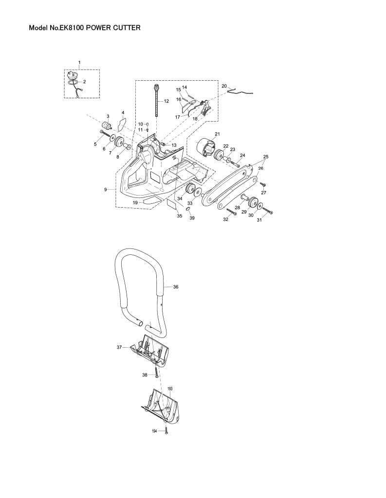
Makita EK8100 Parts Breakdown and Overview
In any mechanical system, having a clear overview of its components is crucial for efficient operation and maintenance. By analyzing the layout and connections between various elements, one can gain insight into how the entire unit functions, ensuring proper care and troubleshooting when necessary.
Visual representation of the individual elements allows for a more intuitive understanding of the assembly. This helps identify specific areas that might require attention, from minor adjustments to more complex repairs.
Furthermore, the detailed breakdown of each section makes it easier to locate key elements, ensuring that any replacement or maintenance is carried out swiftly and accurately. It’s an essential tool for both professional technicians and those seeking to maintain equipment in top working condition.
Overview of Makita EK8100 Components
The structure of this powerful tool is built around a series of essential elements, each designed for durability and precision. These parts work together to ensure high performance and reliability, even in the most demanding tasks. Understanding the different components can help improve maintenance and troubleshooting efficiency.
Engine system forms the core, driving the machine’s operations with consistent power output. With robust engineering, it delivers the force needed to handle various materials. The internal mechanisms are crafted for smooth function, ensuring longevity under tough conditions.
Another key section is the cutting assembly, responsible for precise and efficient cuts. This area is equipped with sharp and durable elements that maintain their edge over prolonged use. Proper care of this assembly ensures optimal performance over time.
Main Features of the EK8100 Model
This equipment is designed for demanding tasks, offering outstanding reliability and performance. With its powerful engine, users can achieve efficient results in a variety of challenging environments. Durability and ease of use make this model a solid choice for professionals who seek high-quality performance in their tools.
Engine Efficiency and Power

One of the key strengths lies in its high-output engine. This feature ensures rapid cutting and optimal performance under heavy workloads. Additionally, the advanced technology helps maintain consistent power delivery, even during extended operation.
- High power output for quick, clean cuts
- Reliable engine with low fuel consumption
- Optimized for continuous use without overheating
Durability and User Comfort
Built with robust materials, this model is crafted to withstand tough conditions. It not only offers durability but also focuses on user comfort, integrating features that reduce fatigue during prolonged use.
- Sturdy frame designed for long-term use
- Ergonomic design for reduced operator strain
- Effective vibration dampening to enhance comfort
How to Identify Key Engine Parts
Understanding the essential components of an engine is crucial for anyone looking to maintain or repair it. Each piece plays a significant role in ensuring the engine functions smoothly, and recognizing these elements can simplify troubleshooting or upgrades.
Main Structural Elements
The core of the engine consists of several critical sections that work together to generate power. These sections include components responsible for converting energy and those ensuring smooth internal movements. By familiarizing yourself with their shapes and positions, you can easily locate them during inspections.
Moving Components
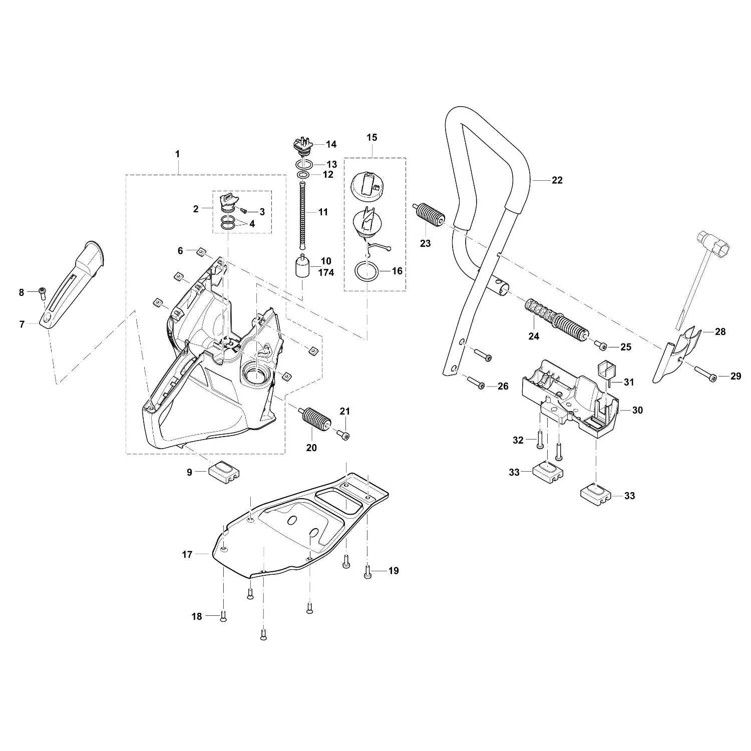
The moving elements within an engine are responsible for generating motion and transmitting power. These parts are typically subject to wear and tear, so identifying them early can help with timely maintenance. Pay attention to components that require regular lubrication to prevent unnecessary damage.
Cutting System Components of the EK8100
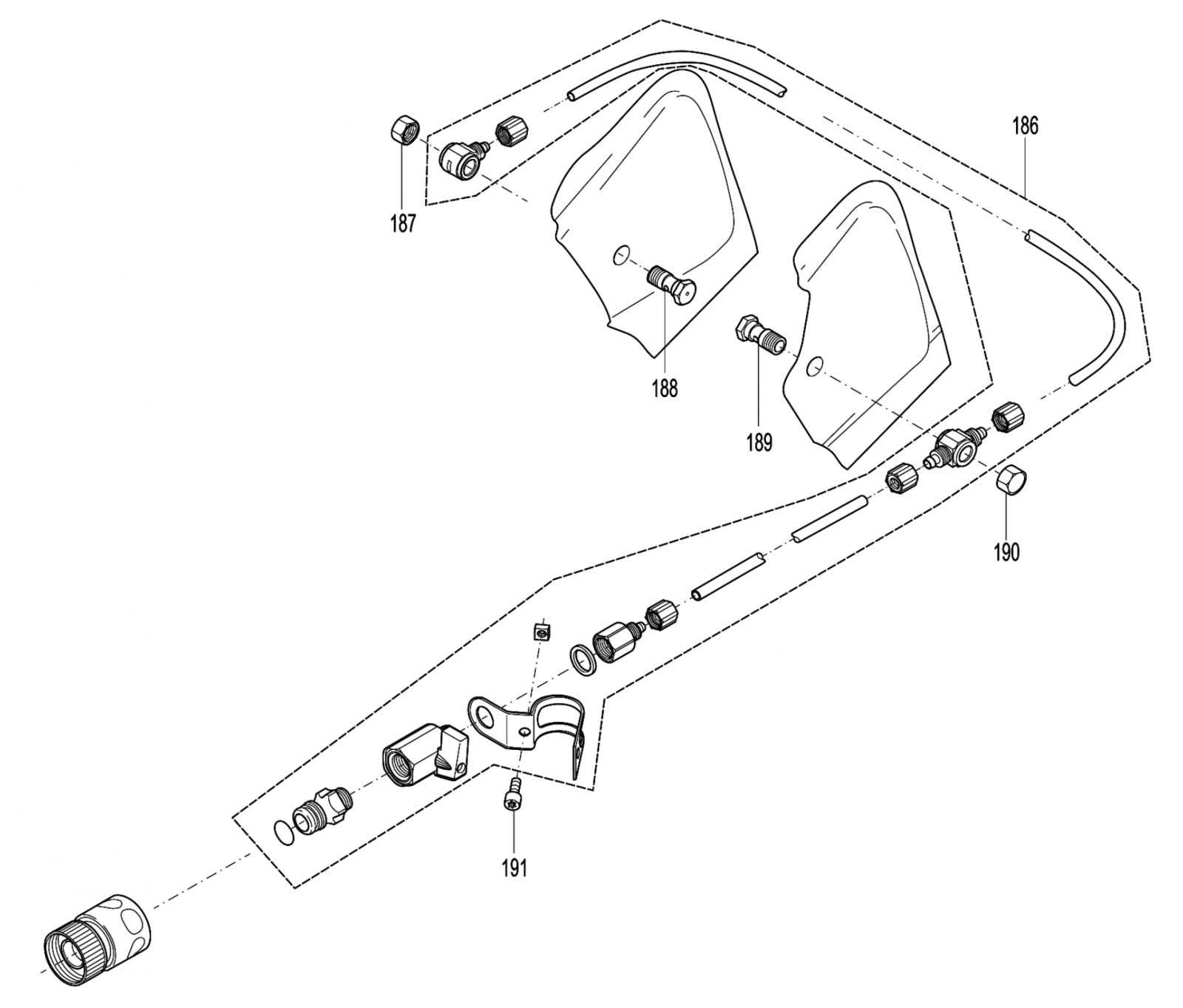
The cutting system of this power tool is a precise assembly designed to deliver high-performance results. Each element plays a crucial role in ensuring effective cutting, contributing to the machine’s overall efficiency and reliability. In this section, we will explore the key elements responsible for smooth operation and durability, highlighting the importance of each component.
Key Elements of the Cutting Mechanism
- Blade Guard: Provides protection during operation, ensuring safety while directing debris away from the user.
- Drive Belt: Transfers power efficiently from the engine to the cutting disc, maintaining stable performance during heavy workloads.
- Cutting Disc: The main element responsible for material removal, designed for durability and precision across a variety of surfaces.
Additional Components for Safe Operation
- Vibration Dampers: Minimize vibration to ensure user comfort during extended use and reduce wear on the internal components.
- Handle System: Ergonomically designed for better grip and control, essential for accurate and secure handling
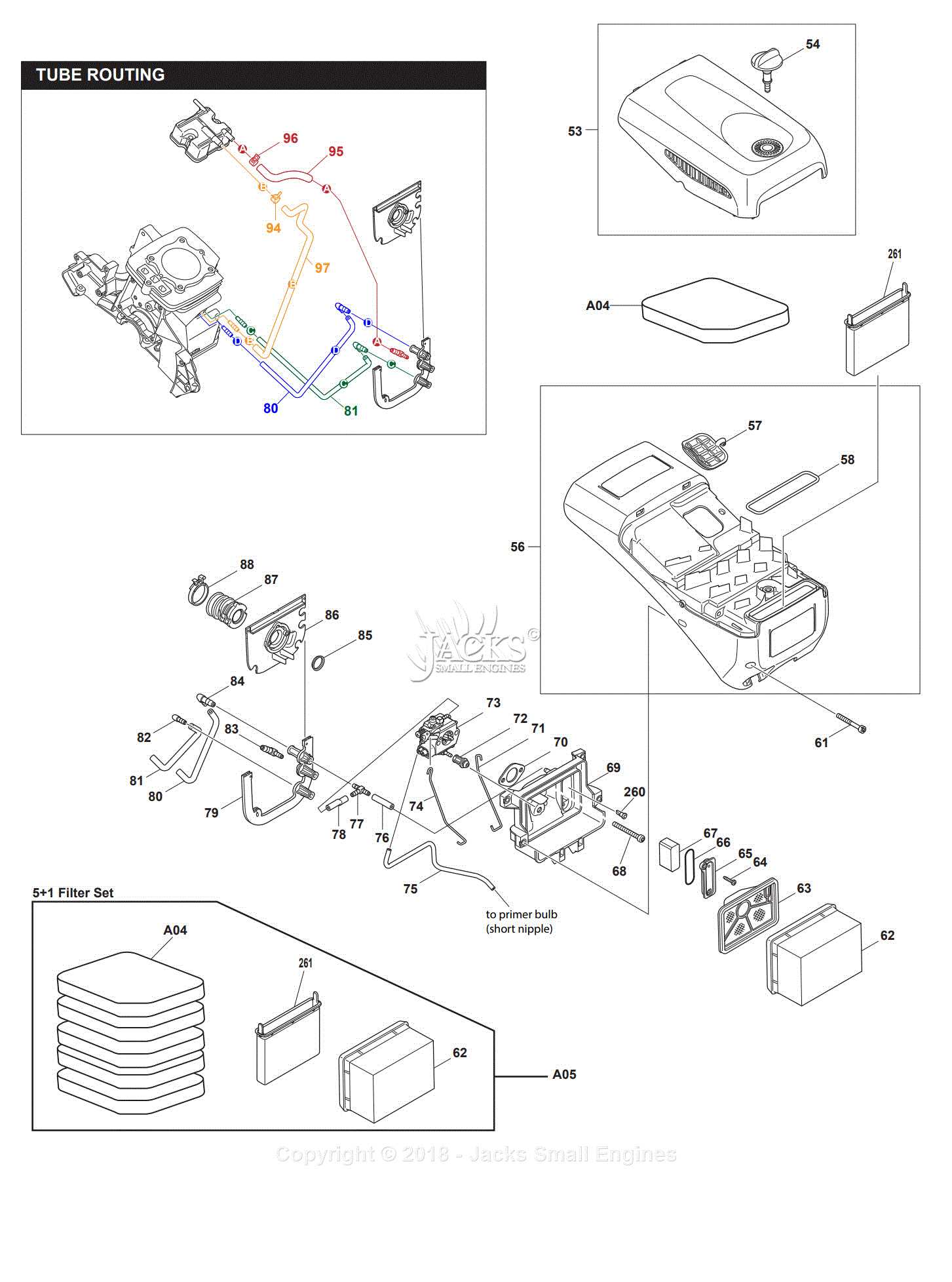
Air Filter and Maintenance Parts
Regular upkeep of essential components ensures the smooth functioning of equipment. Among these, the air filtration system plays a crucial role in preventing debris from entering the engine, which can lead to operational issues. Maintaining this element is vital to prolong the machine’s lifespan and ensure reliable performance.
Cleaning and Replacing the Filter is a straightforward process, but it’s important to follow recommended intervals. Over time, dust and dirt accumulate, potentially clogging the filter and reducing efficiency. Regular inspection and proper cleaning help maintain optimal airflow, ensuring smooth operation.
Additional upkeep elements such as spark plugs and fuel lines are equally important. These items should be checked periodically to prevent potential malfunctions. A consistent maintenance routine can prevent larger issues and reduce the need for significant repairs, ultimately saving time and cost in the long run.
Ignition System: Key Parts and Function
The ignition mechanism plays a crucial role in the operation of outdoor power equipment, ensuring that the engine starts efficiently and runs smoothly. Understanding the essential components of this system can help users maintain and troubleshoot their devices effectively.
Main Components
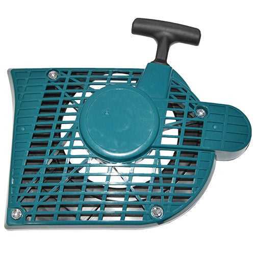
- Ignition Coil: This component transforms the battery’s low voltage into the high voltage required to create a spark.
- Spark Plug: This part ignites the air-fuel mixture within the engine’s combustion chamber, initiating the power cycle.
- Flywheel: As the engine rotates, the flywheel’s magnets generate a magnetic field that activates the ignition coil.
- Ignition Module: This electronic device controls the timing and duration of the spark, ensuring optimal engine performance.
Functionality Overview
When the user pulls the starter cord, the flywheel spins, producing a magnetic field. This action prompts the ignition coil to generate a high-voltage current, which travels to the spark plug. Upon reaching the spark plug, the current creates a spark that ignites the air-fuel mixture, causing combustion. This cycle repeats, providing the necessary power for the equipment to function efficiently.
Fuel System Components Breakdown
The fuel system plays a crucial role in the efficient operation of a combustion engine. It is responsible for delivering the right mixture of fuel and air to the engine, ensuring optimal performance and reliability. Understanding the various elements within this system is essential for effective maintenance and troubleshooting.
Fuel Tank: This component stores the fuel before it is transported to the engine. It is designed to be durable and resistant to corrosion, often featuring a cap to prevent contamination and evaporation.
Fuel Filter: Positioned between the fuel tank and the engine, this element removes impurities from the fuel, protecting the engine from damage and ensuring smooth operation. Regular replacement is necessary to maintain efficiency.
Fuel Pump: This device is responsible for moving fuel from the tank to the engine. It can be mechanical or electric, depending on the design. A properly functioning pump ensures consistent fuel delivery and pressure.
Carburetor or Fuel Injection System: These components mix fuel with air in the correct ratio. The carburetor relies on a vacuum to draw fuel into the airflow, while a fuel injection system electronically controls the delivery, enhancing performance and efficiency.
Fuel Lines: These conduits transport fuel between the tank, filter, and engine. They must be secure and free of leaks to prevent loss of fuel and ensure safe operation.
Primer Bulb: Often found in small engines, this component allows users to manually prime the fuel system, facilitating easier starts by drawing fuel into the carburetor before ignition.
Familiarity with these components enhances understanding of engine operation and aids in diagnosing issues, contributing to better maintenance practices and longevity of the equipment.
Understanding the Cooling System Layout
The cooling system is essential for maintaining optimal operating temperatures in various equipment. It ensures that the engine or motor does not overheat, which can lead to significant damage and reduced performance. This layout consists of several key components that work together to dissipate heat efficiently, allowing the machine to operate effectively over prolonged periods.
Key Components of the Cooling System
At the heart of the cooling arrangement are the radiator and fan, which facilitate the movement of air and coolant. The radiator dissipates heat from the engine by transferring it to the surrounding air, while the fan enhances airflow, especially during low-speed operations. Additionally, the water pump circulates the coolant throughout the system, ensuring consistent temperature regulation.
Importance of Proper Functionality
Understanding the layout and functionality of the cooling mechanism is crucial for effective maintenance. Regular inspection of components such as hoses, clamps, and the coolant reservoir can prevent potential failures. Proper upkeep not only extends the lifespan of the equipment but also optimizes its performance, providing reliable service during operation.
Exploring the Drive Mechanism Assembly
The drive mechanism assembly is a critical component in power equipment, responsible for converting energy into motion. Understanding its structure and functionality can enhance maintenance practices and improve overall performance. This section delves into the essential elements of this assembly, shedding light on its operation and significance.
Key Components and Their Functions
At the heart of the drive mechanism lies a series of interconnected parts that work in unison to facilitate movement. These components typically include the drive shaft, gears, and bearings. The drive shaft serves as the central conduit for power transmission, while the gears regulate speed and torque. Bearings play a vital role in reducing friction, ensuring smooth operation and longevity of the assembly.
Maintenance and Troubleshooting Tips
Regular inspection and maintenance of the drive mechanism assembly can prevent unexpected failures. It’s essential to check for signs of wear on gears and bearings and to ensure that the drive shaft is properly lubricated. If issues arise, such as unusual noises or decreased performance, a thorough examination of the assembly should be conducted to identify and resolve any underlying problems.
Handle and Control Parts Diagram
The assembly responsible for manipulation and operation of tools plays a crucial role in ensuring efficiency and comfort during use. Understanding the components involved in this section provides valuable insight into the functionality and maintenance of the equipment. Each element contributes to the overall performance and user experience, making it essential to grasp their arrangement and purpose.
Components Overview
The structure consists of various elements that facilitate control and stability. Key components include grips, trigger mechanisms, and control levers, each designed to enhance user interaction and operational precision. Familiarity with these parts can assist in troubleshooting and optimizing the equipment’s performance.
Maintenance Tips
Regular inspection of the control assembly is vital for maintaining optimal functionality. Ensure that all components are securely attached and free from debris. Lubrication of moving parts can enhance their performance and longevity. Addressing wear and tear promptly can prevent more significant issues down the line.
Troubleshooting with the Parts Diagram
Identifying issues within your equipment can often be simplified through a visual representation of its components. Such a schematic not only assists in understanding the assembly but also helps pinpoint potential faults that may arise during operation. By referencing this visual guide, users can efficiently diagnose and resolve problems, enhancing the overall performance of the machinery.
When attempting to troubleshoot, consider the following steps:
- Examine the visual layout for any missing or damaged components.
- Cross-reference the identified parts with the symptoms observed during use.
- Focus on the connections and interfaces between components that may lead to malfunction.
Common issues that may be resolved by analyzing the schematic include:
- Power failures due to loose connections.
- Performance inconsistencies linked to worn-out parts.
- Unusual noises that can indicate misalignment or breakage.
By systematically reviewing the assembly layout and correlating it with operational difficulties, users can implement effective solutions, ensuring the longevity and reliability of their equipment.