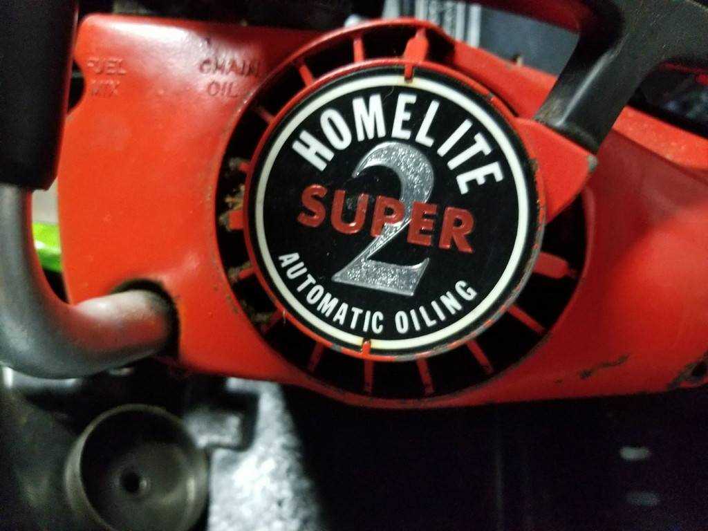
Homelite Super 2 Chainsaw Parts Diagram Guide
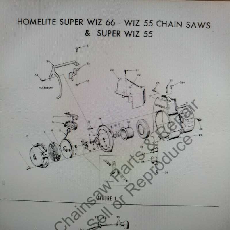
Maintaining any high-performance cutting equipment requires an understanding of its various elements and how they interact to deliver optimal functionality. By exploring the individual components of such a tool, users can enhance performance, ensure safety, and prolong the lifespan of their equipment. This guide focuses on the critical elements that make up one such powerful cutting device, presenting a clear and detailed breakdown of each part’s role in the system.
Understanding the internal mechanisms and external features is key to troubleshooting, maintaining, and optimizing performance. From the intricate engine system to the smallest mechanical connections, each component plays a vital role in keeping the machine operational and efficient. Whether you’re a professional or an enthusiast, gaining knowledge of these individual parts will significantly contribute to your operational success.
With a focus on clarity and detail, this guide offers a step-by-step breakdown of all crucial mechanisms. It will help both beginners and seasoned operators identify, assess, and replace key elements, ensuring that their cutting tool remains in peak condition for years to come.
Understanding the Homelite Super 2 Chainsaw
A versatile and reliable tool is essential for any woodcutting task, providing the user with the necessary efficiency and power to handle both light and more demanding jobs. This particular model has been designed to offer ease of use, durability, and consistent performance in a variety of settings. Knowing how each element functions can significantly improve its operation and longevity.
Understanding the internal mechanics and external components is key to getting the most out of this machine. Whether you’re performing maintenance or troubleshooting, familiarizing yourself with its design and function will ensure smoother performance and reduced downtime. The core of this tool’s operation lies in its streamlined mechanisms, offering a balance between power and precision.
Key Components of the Homelite Super 2
The design of this tool relies on several essential elements working together to ensure smooth and efficient operation. Each part plays a crucial role in both functionality and overall performance, contributing to the tool’s reliability. By understanding the major components, users can better maintain and troubleshoot their equipment, ensuring longevity and safety.
Engine and Power System
At the heart of this machine lies a compact and powerful engine that delivers the necessary force for cutting tasks. The motor is supported by a fuel system that ensures consistent performance, while a cooling mechanism prevents overheating during extended use. Proper maintenance of these elements is key to keeping the machine running smoothly.
Cutting Mechanism and Control Features
The cutting system consists of sharp, durable teeth and a guide that directs movement. This section of the tool is designed for precision and control, allowing users to achieve clean and accurate cuts. Additionally, several control features, including a throttle and safety switches, enhance user handling and reduce potential risks during operation.
Chain Tensioner and Guide Bar Overview

Proper adjustment and maintenance of key components are crucial for ensuring smooth and efficient cutting operations. Two important elements in this process are the mechanism responsible for adjusting tension and the guiding track that supports the cutting tool. When these elements function correctly, they allow for consistent performance and enhance the durability of the equipment.
Function of the Tension Mechanism
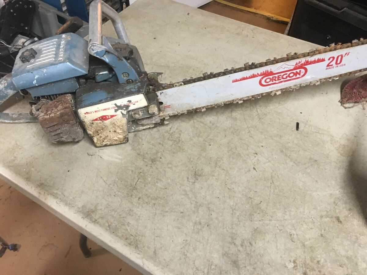
The tensioning mechanism plays a vital role in maintaining the optimal tightness of the cutting loop. Keeping it at the right level prevents excessive wear and ensures that the tool remains secure during operation. A well-adjusted tensioner also minimizes the risk of slippage and potential damage to the system.
Guide Bar Characteristics
The guiding track serves as a solid foundation for the cutting element, ensuring precision and stability throughout the process. Its proper alignment and upkeep are essential for reducing friction and preventing unnecessary strain on the machine. Regular inspection and timely adjustments will prolong the lifespan of this crucial component.
Regular maintenance of these parts is essential for efficient performance and safety. Neglecting them can lead to reduced effectiveness and increase the risk of malfunctions.
Fuel System and Carburetor Layout
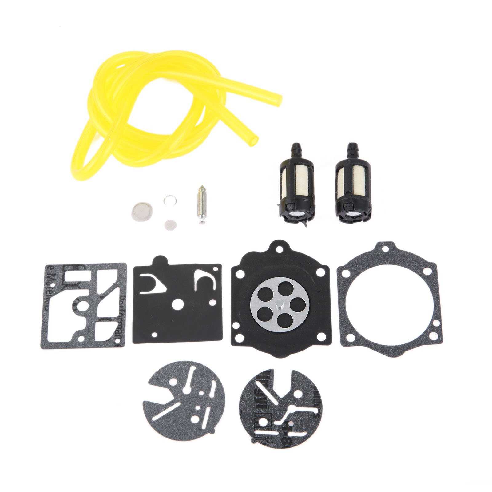
The engine’s fuel system plays a crucial role in ensuring efficient combustion by delivering the right mixture of air and fuel. A properly functioning layout involves several components that work together to regulate the flow of fuel and control the air intake. Understanding this setup is key to maintaining optimal performance and avoiding mechanical issues.
Fuel Lines transport gasoline from the tank to the carburetor, and any disruptions in these lines, such as leaks or blockages, can impact the entire operation. It’s essential to regularly inspect these connections for wear or damage.
The carburetor itself is responsible for blending air with fuel before delivering the mixture to the engine. A clean and well-tuned carburetor ensures smooth operation, while debris or incorrect settings can cause sputtering or engine failure.
The primer bulb, a small yet vital component, helps draw fuel into the carburetor for easier starting. This part is especially useful after long periods of inactivity when fuel may not be readily available in the system.
By maintaining each aspect of this system, from the fuel lines to the carburetor, one can ensure reliable performance and prevent common malfunctions that arise from improper fuel delivery.
Ignition System Parts and Operation
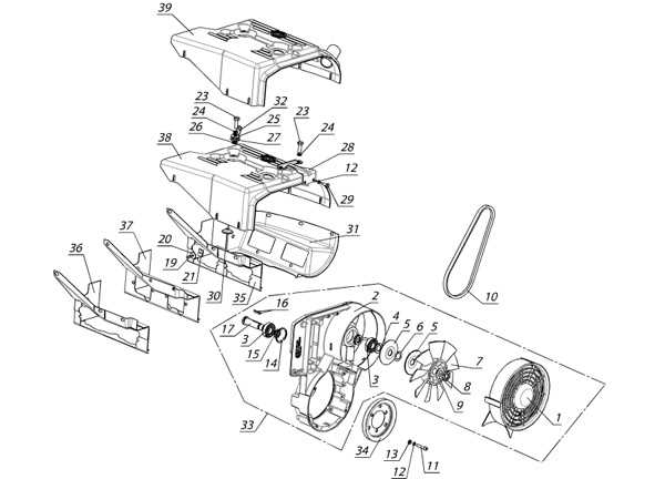
The ignition system is responsible for starting the engine by creating a spark that ignites the air-fuel mixture. This process ensures the engine runs smoothly and efficiently, coordinating with other components to maintain consistent operation. Understanding the key elements and their functions helps diagnose issues or maintain the system effectively.
Main Components
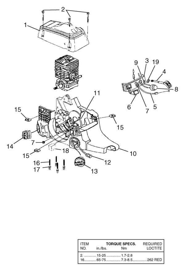
- Flywheel: A rotating component that generates energy through motion, working in sync with the rest of the system to produce the necessary spark.
- Magneto: Converts mechanical energy into electrical energy, creating the high-voltage current needed for the spark plug to ignite the mixture.
- Spark Plug: A critical device that delivers the electrical charge, creating the spark required to initiate combustion in the engine.
- Ignition Coil: Boosts the low voltage from the magneto to a higher voltage, allowing the spark to jump the gap in the spark plug.
- Kill Switch: Provides a safety feature
Oiling Mechanism and Lubrication Points
The proper functioning of any cutting tool is highly dependent on its lubrication system. This system plays a crucial role in reducing friction between moving components, ensuring smooth operation and longevity. Adequate oiling not only enhances performance but also prevents premature wear and tear, which can lead to costly repairs or replacements.
In this context, the lubrication points are strategically located throughout the device. These areas typically include the bar and chain assembly, where oil is essential for efficient cutting. Ensuring these points receive the appropriate amount of lubricant is vital for optimal functionality. The oiling mechanism usually operates automatically, dispensing lubricant as needed during use, thereby maintaining a consistent flow to critical components.
Users should regularly check and refill the lubricant reservoir to avoid any interruptions in performance. Additionally, inspecting the lubrication points for clogs or wear can help identify potential issues before they escalate. A well-maintained lubrication system is key to achieving peak efficiency and prolonging the life of the equipment.
Starter Assembly and Pulley Mechanism
The starter assembly and pulley mechanism play a crucial role in the efficient functioning of any portable cutting tool. This system is designed to facilitate the initial ignition process, ensuring a smooth and reliable start each time the engine is engaged. Understanding the components involved can aid in effective maintenance and troubleshooting.
Key components of the starter assembly include:
- Starter Handle: The user interface for initiating the starting process.
- Pulley: A circular device that transmits motion through a rope or cord.
- Spring: Provides the necessary tension to retract the cord after pulling.
- Mounting Plate: Secures the assembly to the engine casing.
- Cord: The mechanism that connects the handle to the pulley for operation.
Proper installation and maintenance of these components are essential for optimal performance:
- Ensure the cord is free from frays and wear.
- Check the spring for adequate tension and replace if needed.
- Regularly clean the pulley to prevent debris buildup.
- Verify that the mounting plate is securely fastened.
By keeping these elements in good condition, users can achieve a reliable and efficient starting process, enhancing the overall longevity of the tool.
Air Filter Housing and Maintenance Tips
The air filter housing is a crucial component that ensures the engine receives clean air for optimal performance. Regular maintenance of this assembly not only enhances the efficiency of the machine but also prolongs its lifespan. Proper care can prevent dirt and debris from entering the engine, which is essential for smooth operation.
1. Regular Inspection: Frequently check the air filter housing for any signs of wear or damage. Look for cracks or breaks that could compromise its function. Ensuring the integrity of the housing helps maintain an effective filtration system.
2. Clean the Air Filter: Remove the filter from the housing and clean it according to the manufacturer’s guidelines. Use a gentle cleaning solution and rinse it thoroughly. Allow it to dry completely before reinstallation to prevent moisture-related issues.
3. Replace as Needed: If the air filter appears excessively worn or clogged, replacing it is necessary. A new filter ensures that the engine receives adequate airflow, leading to better performance and fuel efficiency.
4. Ensure Proper Sealing: After cleaning or replacing the filter, check that it fits securely within the housing. A proper seal prevents unfiltered air from entering, which could cause damage over time.
5. Follow a Maintenance Schedule: Establish a routine maintenance schedule based on usage and environmental conditions. Keeping to this schedule will help ensure the air filter housing and filter remain in optimal condition.
By adhering to these maintenance tips, users can significantly enhance the performance and durability of their equipment, ensuring it operates at peak efficiency for years to come.
Clutch and Chain Brake Configuration
The interaction between the clutch and chain brake is crucial for the safe and efficient operation of cutting equipment. This section focuses on their arrangement and functionality, ensuring optimal performance during use. Proper configuration not only enhances the machine’s efficiency but also provides necessary safety features to protect the operator.
The clutch system engages and disengages the cutting mechanism, allowing for smooth transitions between idle and active states. The chain brake serves as a protective measure, designed to halt the chain’s movement quickly in case of sudden incidents. Understanding the intricacies of their setup is essential for effective maintenance and troubleshooting.
Component Description Clutch Drum Houses the clutch mechanism and transmits power to the cutting tool. Drive Links Connect the cutting tool to the clutch, allowing for controlled movement. Brake Band Engages with the drum to halt the chain’s movement during emergencies. Chain Brake Lever Manually activates the chain brake, providing immediate stopping capability. Spring Mechanism Ensures the clutch engages smoothly and the chain brake resets automatically. Regular inspection of these components is recommended to prevent malfunctions. Proper maintenance practices contribute to the longevity and safety of the equipment, ensuring that operators can work confidently.
Muffler and Exhaust System Breakdown
The muffler and exhaust assembly are critical components in any engine, playing a vital role in managing the flow of gases produced during combustion. These parts work together to reduce noise levels and channel harmful emissions away from the operator. Understanding the functionality and structure of this system can enhance maintenance practices and improve overall performance.
The muffler is designed to minimize sound produced by the engine while ensuring efficient gas expulsion. It employs a series of chambers and perforated tubes to dissipate noise, allowing the engine to run more quietly. Regular inspection of the muffler is essential, as blockages or damage can lead to increased noise levels and engine performance issues.
Connected to the muffler is the exhaust system, which directs combustion byproducts away from the engine. This system often includes pipes and connectors that must be checked for leaks or corrosion. Any deterioration can adversely affect the engine’s efficiency and could pose safety hazards. Proper maintenance of these components ensures optimal performance and longevity.
In summary, a thorough understanding of the muffler and exhaust system contributes significantly to the effective operation of the engine. Regular maintenance and timely repairs can prevent issues, ensuring a quieter and more efficient experience.
Understanding the Homelite Super 2 Diagrams
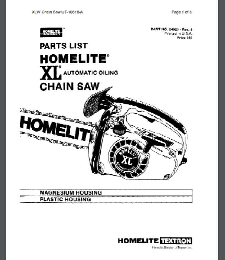
Familiarizing oneself with the intricate visual representations of machinery components is essential for effective maintenance and repair. These illustrations serve as valuable guides, detailing the relationships and functions of various elements within the equipment. By grasping the layout and specific roles of each segment, users can enhance their understanding and proficiency in managing their tools.
Importance of Visual Guides
Visual aids play a crucial role in the repair process. They simplify complex information, allowing individuals to identify specific areas that require attention. By using these visual references, users can ensure that they are handling components correctly and efficiently, reducing the risk of errors during assembly or disassembly.
Key Components to Identify
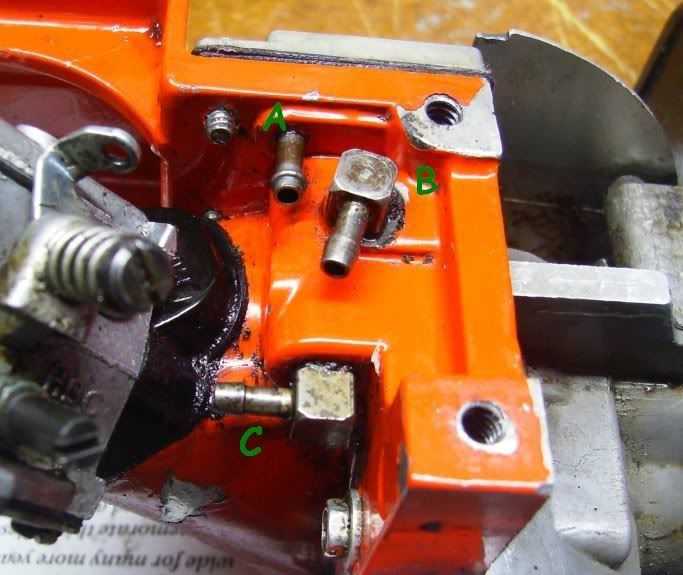
Recognizing essential elements within the machinery is vital for troubleshooting and repairs. The following table highlights some of the primary components commonly found in these visual representations:
Component Description Engine The power source that drives the tool. Fuel System Includes the tank and lines that supply energy to the engine. Bar and Chain The cutting assembly responsible for slicing through materials. Safety Features Devices that ensure safe operation, such as brake mechanisms. Handle and Controls The user interface that allows for manipulation and steering of the equipment.