Understanding the Fal Parts Diagram for Enhanced Maintenance

In the realm of mechanical and electronic systems, comprehending the intricate arrangements of various elements is essential for effective functionality. Each system comprises multiple units that work in harmony, contributing to the overall operation and efficiency. By analyzing the configuration of these units, one can gain valuable insights into the design and maintenance of the system.
The visualization of these configurations plays a crucial role in troubleshooting and enhancing performance. By exploring the intricate relationships between different components, users can identify potential issues and optimize workflows. This understanding also facilitates better communication among professionals involved in design, repair, and development.
In this exploration, we delve into the significance of detailed representations that illustrate the interactions and placements of these units. Such visual tools not only serve as guides for assembly and repair but also enrich our knowledge of how each piece contributes to the functionality of the entire system.
Understanding Fal Parts Diagram

Grasping the intricacies of an assembly blueprint is essential for anyone involved in technical fields. These schematics serve as crucial references, illustrating how various components interrelate and function together. By decoding these visual representations, users can enhance their comprehension of mechanical systems and facilitate more effective maintenance and repair processes.
Importance of Visual Representations
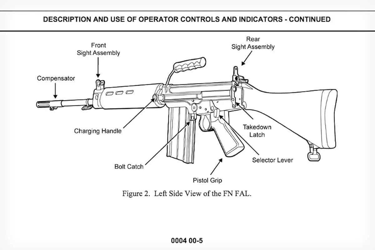
Visual schematics are invaluable tools that provide a clear overview of complex structures. They help technicians identify each element’s role and understand how they integrate into the larger system. This clarity not only streamlines troubleshooting but also aids in the educational development of professionals in the industry.
Key Components to Consider
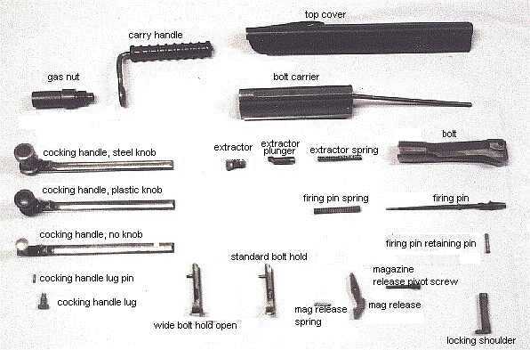
When examining an assembly blueprint, several essential elements should be taken into account to fully appreciate the layout:
| Element | Description |
|---|---|
| Symbol Representation | Unique icons representing various components. |
| Connection Lines | Indicate how different elements are linked and interact. |
| Labels | Provide names or codes for quick identification. |
| Legend | Explains the symbols and notation used throughout the schematic. |
By mastering the interpretation of these elements, individuals can significantly enhance their operational effectiveness within their respective fields.
Importance of Parts Diagrams in Manufacturing
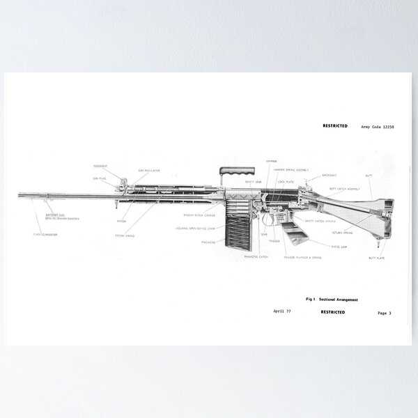
In the realm of production, visual representations play a crucial role in facilitating understanding and communication. These illustrations serve as essential tools that help workers and engineers navigate the complexities of assembly and maintenance processes. By providing clear, detailed views, they enhance both efficiency and accuracy in the manufacturing environment.
One of the primary advantages of these visual aids is their ability to simplify intricate information. When dealing with numerous components, a comprehensive illustration allows teams to quickly identify parts and their functions. This clarity minimizes the risk of errors, which can be costly in terms of time and resources.
Moreover, such representations foster collaboration among different departments. Designers, assemblers, and quality control teams can reference the same visuals, ensuring everyone is on the same page. This unified approach not only streamlines workflow but also enhances problem-solving capabilities, as all stakeholders can pinpoint issues based on a shared understanding of the components involved.
In addition to aiding immediate tasks, these visuals serve as valuable documentation for future reference. They can help new employees acclimate to processes more quickly and provide a reliable source of information for maintenance and repairs. In this way, visual guides contribute to a culture of continuous improvement within manufacturing organizations.
Ultimately, the effective use of these illustrative tools is a cornerstone of modern manufacturing. They bridge the gap between complex designs and practical execution, ensuring that quality and precision remain at the forefront of production efforts.
Key Components Illustrated in Fal Diagram
This section highlights the essential elements depicted in the schematic representation. Understanding these components is crucial for grasping the overall functionality and interconnections within the system. Each element plays a significant role in the operation and efficiency of the mechanism, contributing to its reliability and performance.
Major Elements
The primary components include various modules that interact seamlessly. These modules are designed to optimize processes and ensure that the system operates smoothly. For instance, the central unit acts as the brain, coordinating actions and facilitating communication between other parts. This organization allows for a streamlined workflow and enhances overall efficiency.
Supporting Structures
In addition to the main elements, supporting structures are equally important. They provide stability and ensure that all components function as intended. These frameworks are often designed to withstand external pressures and maintain integrity over time. The synergy between the main units and supporting structures is vital for achieving optimal performance and longevity of the entire assembly.
How to Read a Fal Parts Diagram
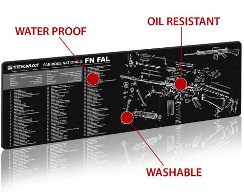
Understanding a technical illustration can greatly enhance your ability to assemble, repair, or maintain a complex machine. These visual guides provide a systematic representation of various components and their interconnections, allowing users to navigate through intricate designs efficiently.
Familiarize Yourself with Symbols
Every schematic uses specific symbols to represent different elements. Familiarization with these icons is crucial. Look for a legend or key that explains each symbol’s meaning. This will help you decode the illustration quickly and prevent confusion when locating particular elements.
Follow the Flow of the Assembly
Each drawing typically displays an organized flow of assembly or disassembly. Pay attention to the arrows and lines indicating movement or connections. Following this flow will guide you through the process step-by-step, ensuring that no crucial details are overlooked.
Common Applications of Fal Parts Diagrams
The utilization of schematic representations is crucial in various industries, providing clarity and understanding of complex systems. These visual aids serve as invaluable resources for professionals who need to identify components and their interrelations efficiently. Their applications span across numerous fields, enhancing communication and streamlining processes.
Maintenance and Repair: One of the primary uses of these visual guides is in the maintenance and repair sector. Technicians rely on them to locate specific elements within machinery, enabling swift troubleshooting and minimizing downtime. By referring to these representations, professionals can pinpoint issues accurately and perform necessary repairs with confidence.
Manufacturing: In manufacturing environments, such illustrations are essential for assembly lines. They provide workers with a clear understanding of how parts fit together, ensuring consistency and quality in production. The use of such visuals facilitates training and helps new employees quickly grasp the assembly process.
Education and Training: Educational institutions leverage these resources to teach students about mechanical systems and engineering concepts. By visualizing the relationships between different components, learners can develop a deeper understanding of the subject matter, leading to better retention of information and practical skills.
Product Development: During the product design phase, these visual tools assist engineers in conceptualizing and refining their ideas. By mapping out the relationships between various components, designers can identify potential issues early in the development process, leading to more efficient and innovative solutions.
Safety and Compliance: In industries where safety is paramount, these visuals play a vital role in compliance and risk management. They help ensure that all components meet regulatory standards and highlight critical areas that require attention, thereby fostering a safer working environment.
Differences Between Various Parts Diagrams
Understanding the distinctions among different schematic representations is crucial for effective analysis and communication. Each type of visual can provide unique insights, catering to specific needs and contexts. By examining these variations, one can better navigate the complexities of the information presented.
Types of Visual Representations
There are several categories of illustrations that serve distinct purposes. For instance, some graphics emphasize the overall layout, while others focus on intricate details. These representations can be divided into two primary forms: those that provide a broad overview and those that delve into specific components. Each approach allows users to grasp various aspects of the subject matter.
Applications and Use Cases
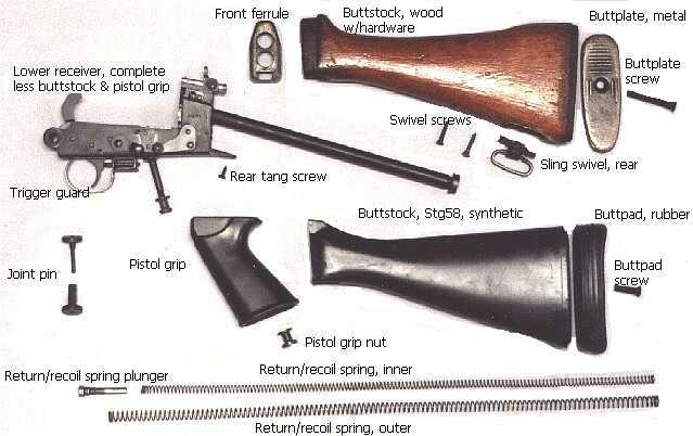
Different illustrations are employed based on the audience and the intended outcome. For instance, a comprehensive overview may be used in educational settings to introduce foundational concepts, while detailed schematics might be preferred in technical fields for troubleshooting. Recognizing these applications helps in selecting the most effective representation for the task at hand. Understanding these nuances ultimately enhances comprehension and efficiency in problem-solving.
Steps to Create a Fal Parts Diagram
Crafting a visual representation of components is essential for understanding the relationships and functions within a system. This guide outlines the essential steps to effectively illustrate these elements, ensuring clarity and coherence in your design.
1. Identify Components
Begin by listing all elements that need to be depicted. Gather detailed information about each item, including dimensions, materials, and interconnections. This foundational step ensures that nothing is overlooked.
2. Organize Information

After identifying the components, organize the data logically. Group similar items and determine the hierarchy of elements to establish a clear flow in your visual. This helps in maintaining an intuitive layout.
| Component | Description | Connection Type |
|---|---|---|
| Item A | Main assembly part | Direct |
| Item B | Support structure | Indirect |
| Item C | Connecting piece | Joint |
Utilize the organized information to create a rough sketch or outline. This preliminary design will serve as the blueprint for your final representation, ensuring all necessary components are included and appropriately positioned.
Software Tools for Diagram Creation

Creating visual representations of complex information is essential for effective communication and understanding. Various software solutions are available that cater to different needs, enabling users to craft detailed and organized visuals that simplify intricate concepts.
Types of Software Solutions
There are several categories of applications designed for this purpose. Vector graphic editors allow for precise control over shapes and layouts, making them suitable for detailed representations. Mind mapping tools facilitate brainstorming and idea organization, providing a more freeform approach to visual thinking.
Key Features to Consider
When selecting a tool, consider features such as collaboration capabilities, which allow multiple users to contribute simultaneously, and template availability, which can streamline the creation process. Additionally, integration with other software can enhance functionality, making it easier to incorporate visuals into larger projects.
Interpreting Symbols Used in Diagrams
Understanding the visual representations in technical illustrations is essential for effective communication and clarity. Symbols serve as a universal language that transcends barriers, conveying complex information in an easily digestible format. By familiarizing oneself with these graphical elements, one can enhance comprehension and facilitate better decision-making in various contexts.
Common Symbol Categories
Symbols can be grouped into several categories based on their function. For instance, indicators often represent components or materials, while arrows may denote direction or flow. Additionally, certain shapes can imply specific characteristics, such as size or connectivity. Recognizing these patterns allows for quicker interpretation and reduces the likelihood of misunderstandings.
Contextual Considerations
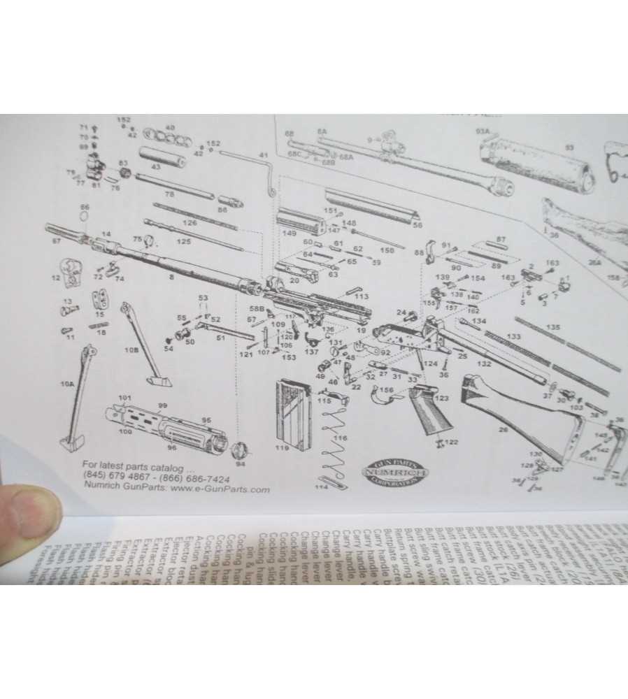
It’s important to consider the context in which these symbols are used, as meanings can vary based on industry standards or particular applications. A thorough understanding of the specific conventions relevant to a field can significantly aid in accurate interpretation. When in doubt, consulting a legend or key accompanying the illustration can provide necessary clarification and enhance overall understanding.
Maintaining Accuracy in Parts Diagrams
Ensuring precision in technical illustrations is crucial for effective communication and functionality. Clear representations not only enhance understanding but also facilitate correct assembly and maintenance. A reliable visual guide can significantly reduce the likelihood of errors and misinterpretations.
Key Practices for Ensuring Precision

- Regular Updates: Keep all visual materials current by incorporating the latest modifications and enhancements.
- Standardization: Adopt uniform symbols and labeling conventions to promote clarity and consistency across all illustrations.
- Verification Processes: Implement thorough checks involving subject matter experts to confirm the accuracy of visual representations.
Tools and Resources
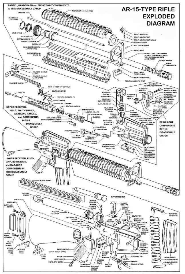
- Software Solutions: Utilize specialized design tools that facilitate precise measurements and scaling.
- Training Programs: Invest in educational resources for team members to enhance their understanding of accurate visual representation.
- Collaboration Platforms: Engage in shared digital spaces for feedback and improvements, fostering a collective approach to accuracy.
Integrating Diagrams into Workflow Processes
Incorporating visual representations into operational procedures can significantly enhance understanding and efficiency. These graphical tools provide clarity, making complex information more accessible to team members and stakeholders. By effectively embedding these visuals into workflows, organizations can streamline communication and foster collaboration, ultimately leading to improved outcomes.
To successfully integrate visuals into workflows, consider the following key strategies:
| Strategy | Description |
|---|---|
| Identify Critical Areas | Determine which processes would benefit most from visual aids, focusing on areas that are complex or prone to misunderstanding. |
| Standardize Formats | Establish a consistent approach for visual tools, ensuring that all team members understand the symbols and conventions used. |
| Integrate with Software Tools | Utilize project management and collaboration platforms that support the incorporation of visual aids directly into workflows. |
| Encourage Team Participation | Involve team members in the creation and modification of visuals, promoting ownership and increasing engagement. |
| Provide Training | Offer training sessions to help team members become proficient in interpreting and using visual representations effectively. |
By focusing on these strategies, organizations can harness the power of visual aids to improve their operational efficiency and enhance team collaboration, ultimately leading to better project outcomes.
Case Studies: Successful Diagram Usage
This section explores real-world examples where visual representations have significantly enhanced understanding and communication within various fields. These case studies illustrate how structured visuals can simplify complex information, foster collaboration, and improve outcomes across diverse industries.
One notable instance occurred in the automotive sector, where a leading manufacturer implemented visual schematics to streamline their assembly line processes. By providing clear visual guidance, workers reduced assembly errors by 30%, resulting in a more efficient production cycle. This approach not only improved output but also boosted employee morale, as team members felt more confident in their tasks.
In the healthcare industry, a hospital adopted visual representations to optimize patient flow. By utilizing flowcharts to map the patient journey from admission to discharge, the staff identified bottlenecks in the system. As a result, they were able to reduce patient wait times by 25%, enhancing overall satisfaction and care quality.
| Industry | Challenge | Solution | Outcome |
|---|---|---|---|
| Automotive | High assembly errors | Visual schematics | 30% reduction in errors |
| Healthcare | Long patient wait times | Flowcharts for patient journey | 25% reduction in wait times |
These examples underscore the transformative power of effective visual tools in driving improvements and achieving strategic goals. By harnessing the clarity and insight that visuals provide, organizations can navigate complexities more adeptly and foster a culture of continuous improvement.
Future Trends in Parts Documentation
The landscape of technical documentation is evolving rapidly, driven by advancements in technology and changing user expectations. As industries increasingly demand more efficient and accessible information, the future of documentation is likely to be characterized by greater interactivity, enhanced visual aids, and a shift toward digital solutions. This transformation aims to facilitate a seamless experience for users, ensuring they have the resources they need at their fingertips.
Innovative Approaches to Documentation

New methodologies are emerging that prioritize user engagement and information clarity. These include:
- Augmented Reality (AR): Integrating AR technology to provide immersive experiences, allowing users to visualize components in real-world settings.
- Interactive Manuals: Utilizing clickable elements and multimedia content to create dynamic guides that adapt to user input.
- Cloud-Based Solutions: Storing documentation in the cloud to ensure easy access and real-time updates across devices.
Enhanced User-Centric Features
The focus on user experience is leading to the incorporation of features that cater to diverse needs:
- Personalization: Allowing users to customize their documentation interface and content based on preferences.
- Smart Search: Implementing AI-driven search capabilities to quickly locate specific information.
- Collaborative Tools: Providing platforms for users to share insights and contribute to documentation, fostering a community-driven approach.
As these trends gain traction, the future of documentation promises to be more accessible, engaging, and effective, ultimately enhancing the overall experience for users across various sectors.