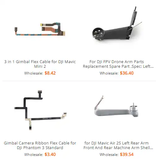
Mavic 2 Parts Diagram Overview
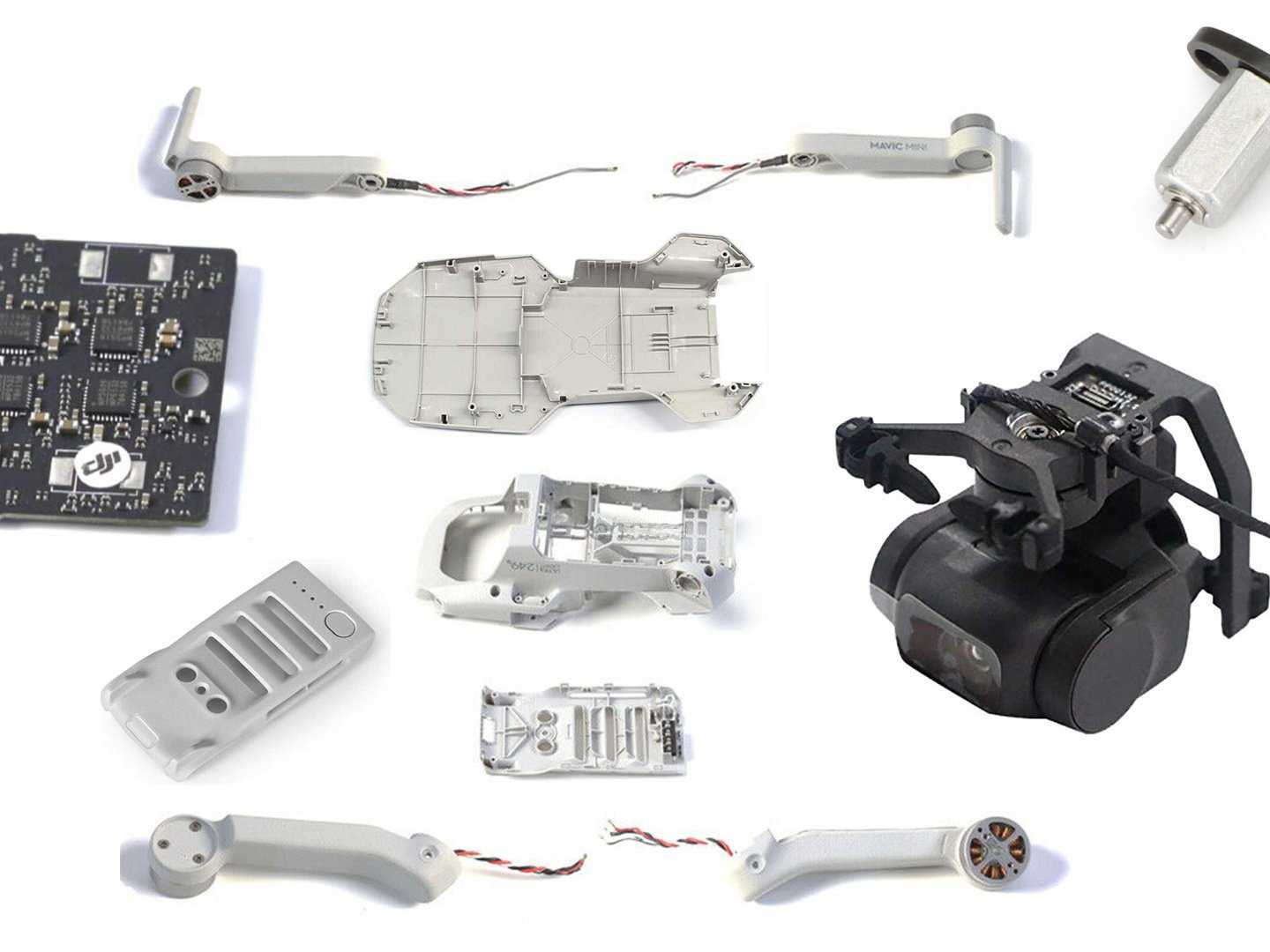
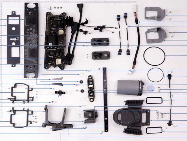
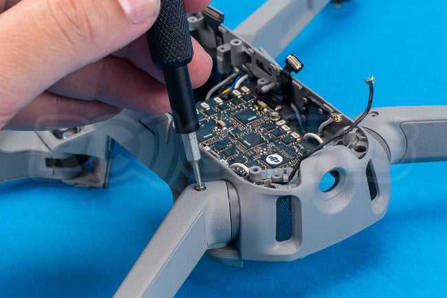
Understanding the various elements that make up a high-performance flying device can significantly enhance its functionality and maintenance. Each individual piece has a crucial role, contributing to both the stability and control during operation. Knowing these details ensures that any necessary replacements or upgrades can be made efficiently and with confidence.
In this section, we will delve into the primary features of this advanced aerial equipment, breaking down how each section interacts with others. By identifying and understanding these individual aspects, you’ll be able to grasp the overall structure of the drone and its operational efficiency.
Whether you’re looking to improve the longevity of the equipment or simply want to familiarize yourself with its internal workings, a detailed understanding of these components is essential for both hobbyists and professionals alike.
Essential Components Overview
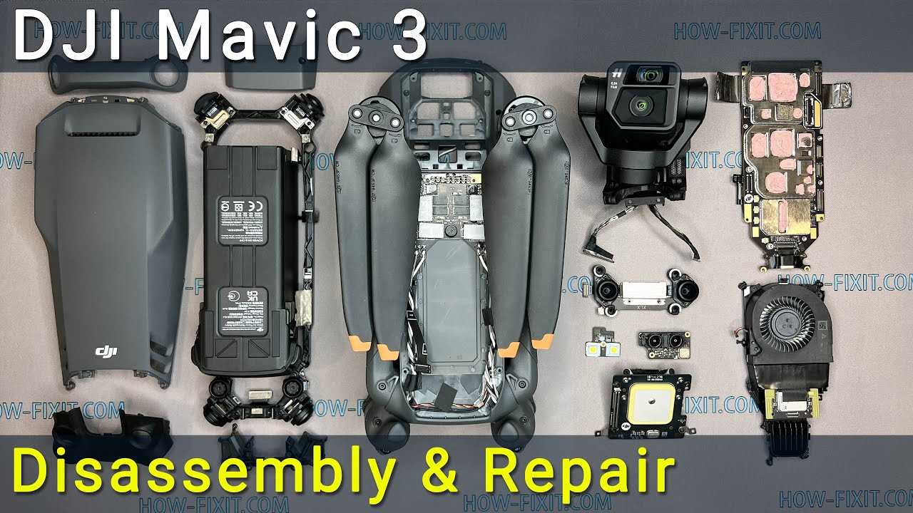
The high-tech quadcopter is built with a combination of crucial elements that ensure optimal functionality during flight. Understanding the key components and their roles can help in maintenance, upgrades, and efficient use of the device.
Main Structural Elements
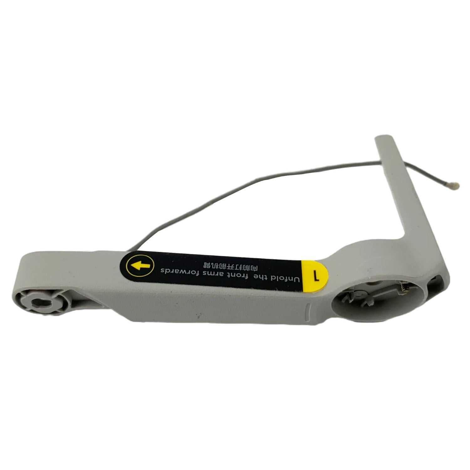
The airframe forms the foundation, holding all other components in place. It is designed to be lightweight and durable, supporting the propellers, motors, and electronic systems. The propulsion system includes high-efficiency motors, combined with propellers, to achieve stable and responsive flight.
Electronic and Control Systems
The control unit coordinates the movement of the aircraft, processing input from sensors and the operator. The battery powers the entire system, ensuring sufficient energy supply for all functionalities. Communication modules allow seamless interaction between the operator and the aircraft, providing real-time data exchange.
| Component | Function | ||||||||||||||||||||||||||||||||||||||||||||||||||
|---|---|---|---|---|---|---|---|---|---|---|---|---|---|---|---|---|---|---|---|---|---|---|---|---|---|---|---|---|---|---|---|---|---|---|---|---|---|---|---|---|---|---|---|---|---|---|---|---|---|---|---|
| Airframe | Provides structural support | ||||||||||||||||||||||||||||||||||||||||||||||||||
| Motors and Propellers | Ensure stable and efficient propulsion | ||||||||||||||||||||||||||||||||||||||||||||||||||
| Control Unit | Manages movement and flight stability | ||||||||||||||||||||||||||||||||||||||||||||||||||
Battery
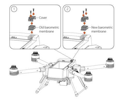
Main Frame Structure of the Mavic 2The central framework of this aerial device serves as the core, holding together all essential components that contribute to its overall stability and performance. This section provides insight into the foundational elements that ensure durability and support for the entire system during flight operations.
Understanding this core section is crucial for both maintenance and enhancement, as it directly impacts the reliability and longevity of the aerial device. Propeller Design and FunctionsPropellers play a crucial role in flight dynamics by providing the necessary thrust to lift and maneuver a drone. Their design directly influences the efficiency, stability, and responsiveness of the entire aerial system, making them an essential component of overall flight performance. Aerodynamic StructureThe design of the propellers is optimized to balance speed and control. The blades are angled in a specific way to maximize lift while minimizing drag, ensuring smooth airflow during operation. This precise engineering helps to reduce noise levels and improve the overall energy efficiency of the drone. Functions of the Propellers
Motor Assembly for Mavic 2
The propulsion system plays a crucial role in ensuring stable flight, smooth maneuvering, and overall performance. A well-maintained engine structure is essential for the optimal functioning of aerial vehicles, allowing precise control and responsive handling in various conditions.
Battery Housing and Connection Points
The structure enclosing the energy source is designed to provide both protection and efficient operation. It ensures that the power supply is safely stored, while allowing for secure attachment to the main body. The positioning of the connecting interfaces plays a vital role in maintaining proper energy flow and safe usage. Design and MaterialThe casing is typically crafted from lightweight, durable materials that offer resilience to environmental conditions. It serves as a shield for the internal components, safeguarding against impact and wear during use. Connection points are strategically positioned to ensure a firm and stable link, preventing accidental disconnection during operation. Power Interface and Safety FeaturesSpecial attention is given to the power interface to ensure it facilitates seamless energy transfer. The connectors are designed to minimize wear over time while maintaining a secure connection. Integrated safety features help prevent power surges, ensuring long-lasting performance and protecting the system from potential hazards. Landing Gear Layout and Stability
The arrangement of the landing apparatus plays a crucial role in the overall balance and functionality of an aerial device. An effective design ensures that the craft remains stable during takeoff and landing, minimizing the risk of accidents. Understanding the positioning and configuration of these components is essential for optimizing performance and enhancing safety. Configuration for Optimal BalanceA well-thought-out structure of the landing gear is vital for achieving proper weight distribution. By strategically placing the legs and support elements, manufacturers can enhance the stability of the aerial vehicle. This careful planning not only aids in a smoother landing but also improves the craft’s resilience against uneven surfaces. Impact on Flight PerformanceThe design of the landing system significantly influences the flight experience. A stable landing gear contributes to a more controlled descent, which can affect maneuverability during aerial operations. Additionally, the durability of these components is paramount; they must withstand various environmental conditions while maintaining their integrity. Camera Mount and Stabilization SystemThe attachment and balancing mechanism plays a crucial role in enhancing the quality of aerial imagery. This assembly ensures that the imaging device remains stable during flight, thereby capturing clear and steady visuals. The design incorporates advanced technology to minimize vibrations and maintain precision, allowing users to achieve professional results even in challenging conditions. Design Features
Engineered for optimal performance, the support structure offers several key attributes:
Operational BenefitsThe integration of this mounting system significantly improves user experience by providing enhanced flexibility and control. It allows operators to focus on composition and creativity without the distraction of unstable footage. Additionally, it enables the use of various imaging devices, catering to diverse filming needs and preferences. Gimbal Parts and AlignmentThe stabilization system is crucial for achieving smooth and steady footage during aerial operations. Understanding the components involved and their precise arrangement can significantly enhance the performance and reliability of the entire mechanism. This section delves into the essential elements of the stabilizing apparatus and how to ensure their correct alignment for optimal functionality. Essential ComponentsThe stabilization mechanism consists of various elements, each serving a specific role in maintaining balance and reducing vibrations. These components include motors, housing, and control boards, which work together to achieve seamless motion. Proper interaction between these elements is vital for the effectiveness of the stabilization system. Alignment TechniquesEnsuring that all components are correctly aligned is critical for the optimal performance of the stabilization system. Misalignment can lead to issues such as vibrations, jittering images, and reduced operational efficiency. Here are some alignment techniques:
Flight Controller Unit BreakdownThe flight control unit serves as the brain of the aerial vehicle, ensuring stable navigation and maneuverability. This central component integrates various functionalities that enable precise flight adjustments and enhance the overall performance of the craft. Understanding its structure and the roles of its individual elements is essential for effective troubleshooting and maintenance. Key Components of the Control UnitAt the core of the control unit are multiple sensors that gather data regarding altitude, speed, and orientation. These sensors work collaboratively to provide real-time feedback, allowing the system to make informed decisions about the craft’s movements. Gyroscopes and accelerometers are particularly crucial, as they detect rotational and linear motion, contributing significantly to the stabilization process. Importance of Firmware and SoftwareThe effectiveness of the flight control unit is also heavily reliant on its software. The embedded firmware facilitates communication between the various sensors and the main processor, ensuring a seamless flow of information. Regular updates to this software are vital for enhancing functionality and integrating new features, thereby improving the overall user experience and reliability of the device. Communication Modules and Signal Transmission
Effective communication is vital for the optimal performance of aerial vehicles. This section delves into the components responsible for transmitting and receiving data, ensuring seamless interaction between the drone and its control system. The reliability of these modules significantly influences the overall functionality and responsiveness of the device. Key Components
Signal Transmission TechniquesVarious methods are utilized to transmit data, each with unique advantages:
Understanding these modules and transmission methods is essential for maximizing the capabilities of the aerial platform. Cooling System Components and Airflow
The effectiveness of any aerial device’s thermal management relies heavily on its integrated components and airflow mechanisms. These systems are designed to maintain optimal operating temperatures, ensuring performance and longevity. Understanding how these elements function together is crucial for achieving maximum efficiency and reliability.
Navigation Sensors and Their PlacementUnderstanding the functionality and positioning of navigation sensors is crucial for ensuring optimal performance in aerial devices. These sensors play a pivotal role in enabling precise maneuvering and enhancing overall stability during flight operations. Their effective integration allows for improved situational awareness and contributes to the safety of the unit. Types of Navigation Sensors
Optimal Sensor PlacementStrategic placement of these sensors is vital for enhancing accuracy and functionality. Here are key considerations:
LED Lighting and Indicators on Mavic 2The incorporation of illumination and signaling mechanisms in aerial devices plays a vital role in enhancing visibility and communication. These features not only provide aesthetic appeal but also serve functional purposes, aiding operators in monitoring the status and activity of the unit during flight. Functionality of LED IndicatorsIllumination components are strategically placed to convey important information regarding the device’s operational status. Different colors and patterns of lights signal various conditions, enabling the user to make informed decisions while piloting. Color Codes and Their Meanings
|
