Ford 7710 Parts Diagram Guide
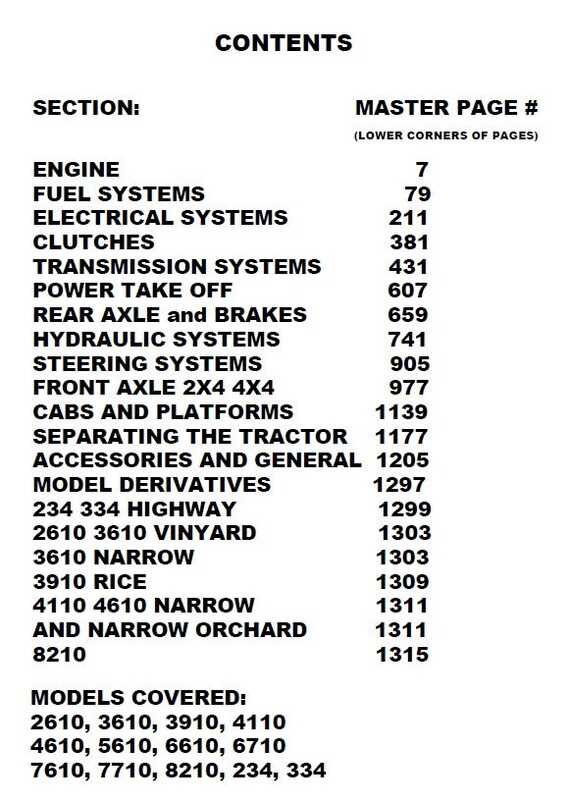
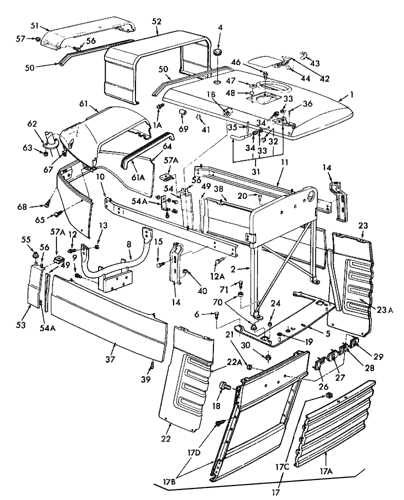
Understanding the layout of various elements within agricultural machinery can greatly assist in maintenance and troubleshooting tasks. A well-structured layout not only provides a visual guide to the essential elements but also helps operators and technicians identify connections and sequences within the equipment.
By exploring the configuration of these essential elements, users can gain insights into how each component contributes to the overall function of the machine. This detailed perspective enables more efficient repairs, effective part replacements, and ensures that equipment continues to operate smoothly.
Whether for repairs or routine upkeep, having a detailed reference guide on the arrangement of machine elements ensures that users can work confidently, reducing downtime and extending the longevity of their machinery. With this resource, maintaining complex equipment becomes an achievable task for both seasoned professionals and those new to the field.
Understanding Ford 7710 Tractor Components
The agricultural machinery we rely on daily is composed of various essential components that ensure smooth operation and high performance. Familiarizing yourself with these elements can aid in better maintenance and effective troubleshooting. A comprehensive understanding of these parts will allow users to keep their equipment running efficiently, ultimately leading to prolonged service life and reduced downtime.
Some key components include the engine system, which provides power to the machine, and the hydraulic system, which is responsible for controlling movements and attachments. Additionally, the transmission plays a critical role in adjusting speeds and handling, while the cooling system prevents overheating during prolonged use. By recognizing and understanding these fundamental systems, operators can ensure their equipment is functioning at its best, regardless of the task at hand.
Locating Engine Parts in the Diagram
Understanding the layout of components within a machine’s power unit can greatly simplify maintenance and repair tasks. By interpreting the illustrated guide, one can easily identify essential sections, allowing for a more efficient approach to locating specific elements within the system. This section provides an overview of how to navigate the diagram, helping users pinpoint the exact location of the required elements.
| Component | Description | Location |
|---|---|---|
| Cylinder Block | Main structure housing the pistons and other essential mechanisms. | Central section of the power unit |
| Crankshaft | Converts the up-and-down motion of the pistons into rotational energy. | Lower portion, beneath the cylinders |
| Oil Filter | Ensures that lubricants remain clean and free from impurities. | Side of the motor, near the oil reservoir |
| Fuel Injector | Delivers fuel directly into the combustion chamber. | Top of the cylinder head |
Hydraulic System Layout Explained
The hydraulic system layout is essential for understanding how hydraulic power is distributed throughout a machine. This system utilizes fluid pressure to transmit force, which is then used to operate various components effectively. Below is a simplified overview of the key elements typically found in a hydraulic layout.
| Component | Function |
|---|---|
| Hydraulic Pump | Generates the fluid flow required to create hydraulic pressure. |
| Control Valves | Direct the flow of hydraulic fluid to different parts of the system. |
| Hydraulic Cylinders | Convert hydraulic energy into mechanical force, enabling motion. |
| Reservoir | Stores hydraulic fluid and helps maintain the system’s fluid balance. |
| Filters | Keep the hydraulic fluid clean, preventing contaminants from entering the system. |
Understanding these core elements provides insight into how hydraulic systems function, ensuring efficient operation and performance across various applications.
Exploring Transmission and Gear Components
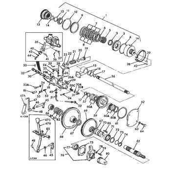
The transmission and gear system is a critical aspect of any machinery, allowing seamless power transfer and enabling a range of speeds and control for various tasks. This section delves into the fundamental components that form the core of this system, highlighting their roles and interactions.
Key Components of the Transmission System
- Clutch Assembly: Engages and disengages the power flow to the transmission, allowing smooth gear shifting and power modulation.
- Gearbox: Contains multiple gears of different sizes, enabling the operator to switch between speeds and control the machinery’s output effectively.
- Driveshaft: Transfers power from the transmission to other parts, ensuring efficient distribution of force throughout the system.
Gears and Their Functions
- Main Gears: These primary gears manage the core speed variations, allowing the machinery to handle different workloads effectively.
- Reduction Gears: Used to reduce speed while increasing torque, providing more force when needed for tougher tasks.
- Synchronization Gears: These gears enable smooth transitions between different speeds, minimizing wear and ensuring longevity.
Understanding these components and their interplay is essential for anyone looking to maintain or operate machinery efficiently. A well-maintained transmission system ensures optimal performance and extends the operational life of the equipment.
Electrical System Parts and Wiring Guide
Understanding the components and layout of an electrical system is essential for ensuring reliable operation and effective troubleshooting. This section provides a comprehensive overview of the key elements involved in the circuitry and connections, focusing on the wiring essentials and various components that contribute to a well-functioning electrical system. From the main power sources to the critical circuits and connectors, we’ll explore how these elements work together to deliver consistent electrical performance and maintain the efficiency of the machinery.
Brake Assembly and Components Layout
The brake assembly serves a critical function in ensuring the safe operation of machinery by providing reliable stopping power. Understanding the layout and various components involved in this system is essential for effective maintenance and troubleshooting. This section will explore the key elements that make up the braking mechanism, offering insights into their arrangement and functionality.
| Component | Description |
|---|---|
| Brake Pedal | The lever that the operator presses to engage the braking system. |
| Master Cylinder | Converts the force from the brake pedal into hydraulic pressure. |
| Brake Lines | Flexible tubes that transmit hydraulic fluid to the brakes. |
| Brake Calipers | Holds the brake pads and exerts pressure on the brake disc to slow down the vehicle. |
| Brake Pads | Friction material that presses against the brake disc to create stopping power. |
| Brake Disc | Rotating component that the brake pads clamp onto for deceleration. |
| Parking Brake | A secondary system that mechanically holds the vehicle stationary when parked. |
Steering System Parts Identification
The steering mechanism of a vehicle plays a crucial role in ensuring accurate control and stability. Understanding the components of this system is essential for effective maintenance and troubleshooting. Identifying each element can aid in diagnosing issues and ensuring smooth operation.
Key Components of the Steering System
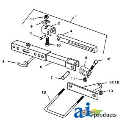
- Steering Wheel: The primary interface for the driver to control the direction of the vehicle.
- Steering Column: Connects the steering wheel to the rest of the system, transmitting the driver’s input.
- Steering Gear: Converts the rotational motion of the steering wheel into linear motion, affecting the direction of the wheels.
- Linkages: These components connect the steering gear to the wheels, allowing for precise movement.
- Power Steering Pump: Provides hydraulic assistance, making it easier to turn the steering wheel.
Common Issues and Solutions
- Worn Out Components: Regular inspection can help identify any parts that may require replacement.
- Fluid Leaks: Monitoring fluid levels is crucial, as low levels can impair steering performance.
- Loose Connections: Ensuring that all linkages are properly secured can prevent steering complications.
Cooling System Components Breakdown
The cooling system is essential for maintaining optimal operating temperatures within machinery, ensuring efficient performance and longevity. Understanding the various components of this system helps in diagnosing issues and performing effective maintenance. This section provides a detailed overview of the key elements involved in the cooling process.
Main Components
- Radiator: This component dissipates heat from the engine coolant, allowing it to cool before returning to the engine.
- Water Pump: This pump circulates coolant through the engine and radiator, facilitating efficient heat transfer.
- Thermostat: A temperature-sensitive valve that regulates the flow of coolant, ensuring the engine reaches its optimal operating temperature.
- Hoses: Flexible tubes that transport coolant between various components, maintaining the system’s circulation.
- Cooling Fan: An electric or mechanical fan that enhances airflow through the radiator, assisting in the cooling process during low-speed operation.
Importance of Maintenance
Regular inspection and maintenance of the cooling system are crucial for preventing overheating and ensuring smooth operation. Common practices include:
- Checking coolant levels and topping up as needed.
- Inspecting hoses for cracks or leaks.
- Flushing the radiator periodically to remove sediment and improve efficiency.
- Testing the thermostat for proper functioning.
Fuel System Diagram and Key Parts
The fuel system plays a crucial role in the operation of any machinery, ensuring that the engine receives the necessary fuel for optimal performance. This section will explore the essential components of this system, detailing their functions and relationships within the overall setup.
Essential Components
Understanding the main elements of the fuel system is vital for maintenance and troubleshooting. Here are the key parts:
- Fuel Tank: Stores the fuel required for operation.
- Fuel Pump: Delivers fuel from the tank to the engine, creating the necessary pressure.
- Fuel Filter: Removes impurities and contaminants from the fuel before it reaches the engine.
- Fuel Injectors: Atomize the fuel, ensuring efficient combustion within the engine cylinders.
- Fuel Lines: Connect the various components, allowing for the flow of fuel throughout the system.
Functionality Overview
Each component of the fuel system has a specific role that contributes to the overall efficiency and reliability of the machinery. A brief overview of their functionalities includes:
- The fuel tank collects and holds fuel until needed.
- The fuel pump draws fuel from the tank and pushes it through the filter.
- The fuel filter ensures only clean fuel enters the engine, preventing damage.
- Fuel injectors precisely deliver the atomized fuel into the combustion chamber for optimal burning.
- Fuel lines facilitate the smooth transition of fuel from one part to another, ensuring uninterrupted service.
Understanding Rear Axle and Differential Parts
The rear axle and differential assembly play crucial roles in the overall functionality of heavy machinery. These components work together to facilitate smooth movement and provide the necessary torque for effective operation. A comprehensive understanding of their structure and interaction is essential for maintenance and repair tasks.
The rear axle is designed to support the weight of the vehicle and transfer power from the transmission to the wheels. It consists of various components, including bearings, seals, and the axle shaft itself. Each element contributes to the stability and efficiency of the system, ensuring reliable performance even under challenging conditions.
The differential serves as a pivotal mechanism that allows for differences in wheel speed during turns, enhancing maneuverability. It comprises gears that engage to distribute torque appropriately, thus preventing tire wear and improving handling. Understanding the intricate workings of the differential is vital for diagnosing issues and ensuring optimal operation.