Johnson 115 Engine Parts Diagram Overview
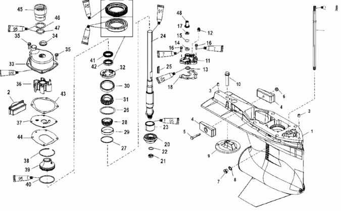
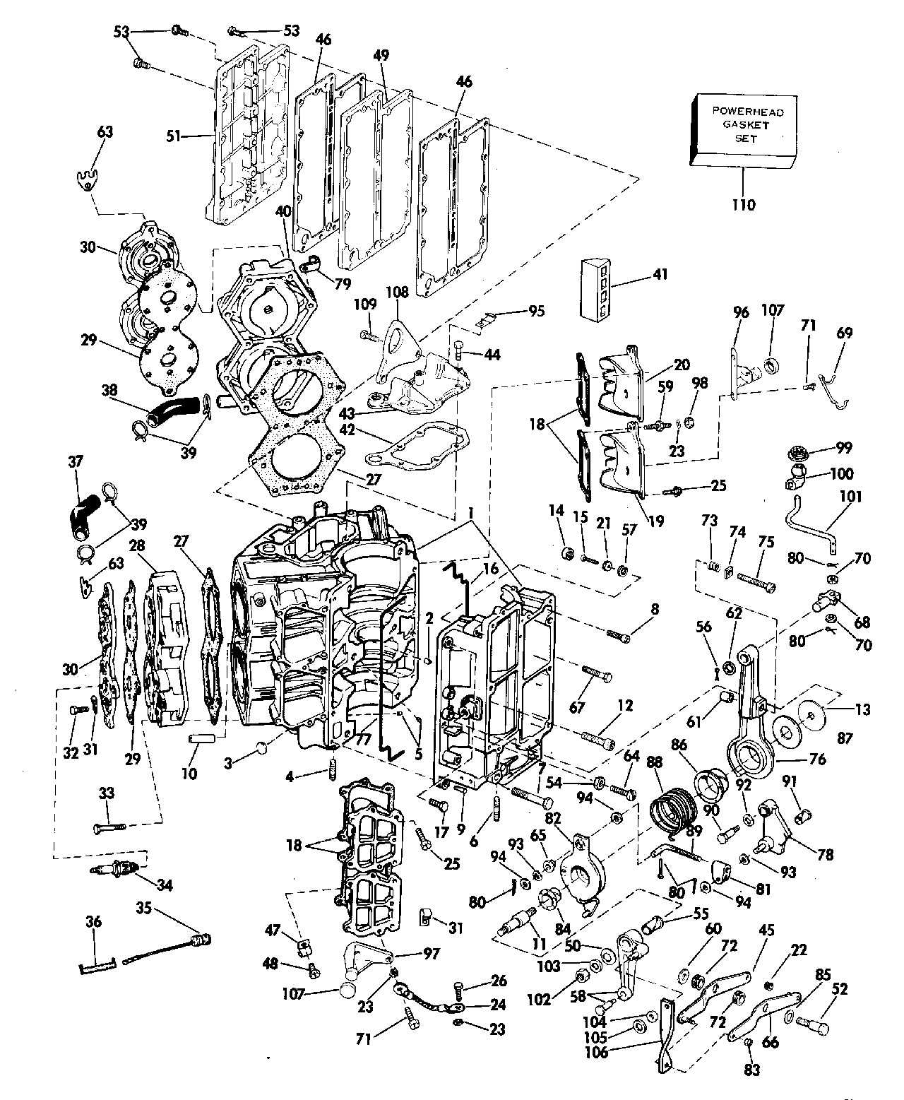
Understanding the internal structure of a complex system is essential for proper maintenance and troubleshooting. Each element plays a significant role in ensuring smooth and efficient operation. Knowing how these elements interact helps to identify potential issues and keep everything functioning optimally.
Key mechanical elements form the foundation of the entire unit, ensuring it operates as expected under various conditions. By studying each piece in detail, one can gain insights into the essential functions, making repairs or adjustments more manageable.
Whether you’re performing routine checks or more detailed repairs, having a clear visual and descriptive guide to each section is invaluable. This approach ensures that even intricate aspects of the mechanism are easily understood, allowing for precision in every step.
Johnson 115 Parts Overview
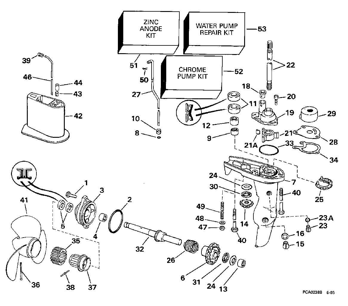
Understanding the key components of this outboard engine can enhance both maintenance and performance. By familiarizing yourself with the essential elements, you ensure smoother operation and easier troubleshooting. Each section of the engine plays a significant role, contributing to overall reliability and efficiency.
Core elements like the power unit, fuel system, and ignition are designed for durability, but regular attention can prevent wear. Additionally, the cooling mechanism, exhaust system, and electrical connections should be examined to maintain peak performance.
Proper care of these crucial elements guarantees the longevity of the engine, making routine inspection and timely replacements vital for continued efficiency.
Main Components of Johnson 115 Engine
The structure of this outboard motor includes several key elements that work together to provide reliable performance. Each part plays a crucial role in ensuring the engine runs smoothly and efficiently in various conditions. Understanding the primary elements is essential for maintenance and troubleshooting.
Power Unit
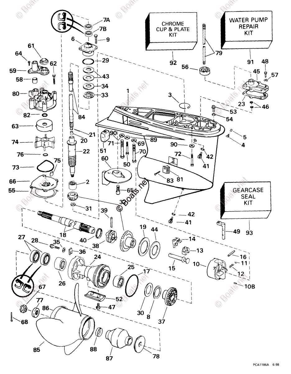
The core section of the motor generates the energy needed to propel the vessel. This segment includes the combustion system, which converts fuel into motion. The balance between fuel intake and combustion efficiency is crucial for overall engine performance.
Cooling and Exhaust Systems
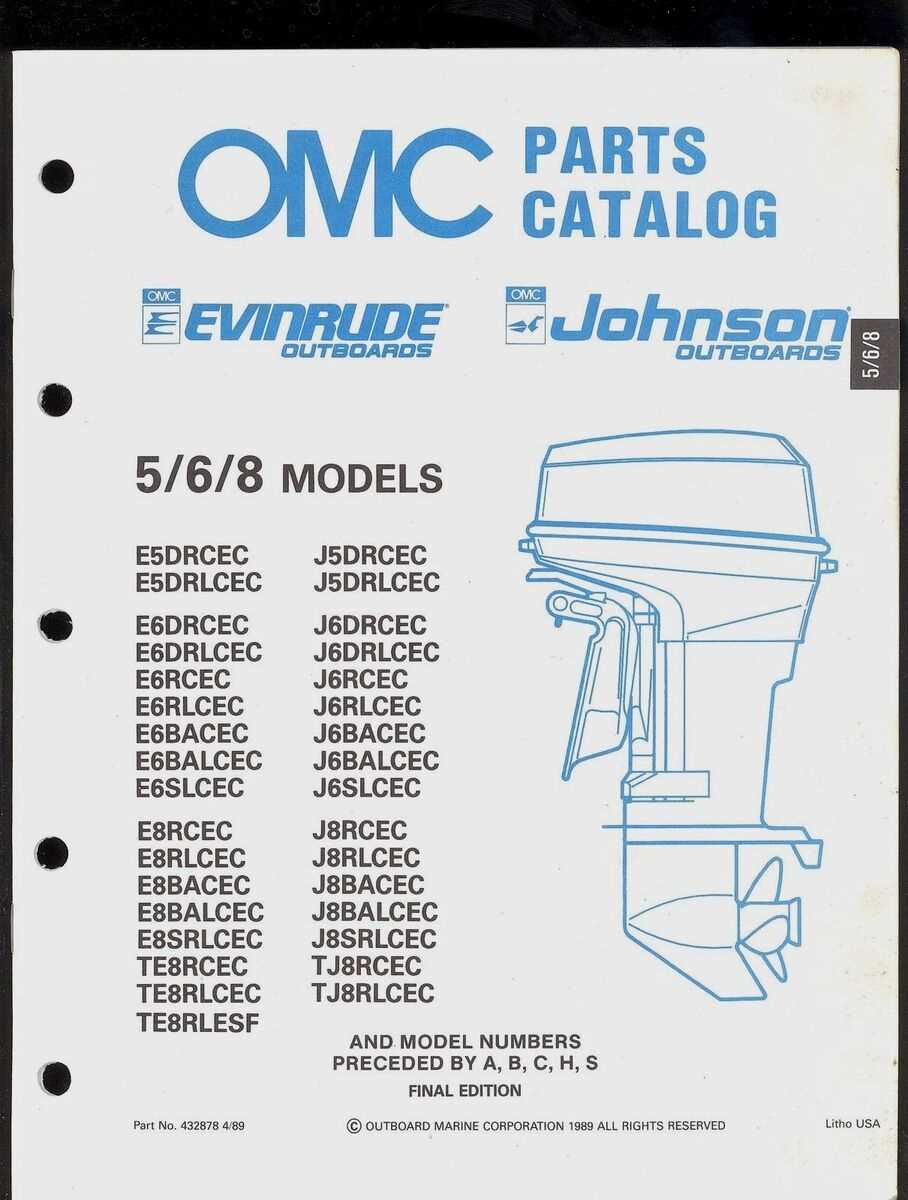
A well-functioning cooling setup is vital for preventing overheating. It circulates water to maintain optimal temperature levels. Additionally, the exhaust system ensures that by-products from combustion are efficiently expelled, maintaining the cleanliness and longevity of the motor.
Exploring the Fuel System Diagram
The fuel delivery structure plays a critical role in ensuring the smooth operation of any engine. By understanding how each component interacts within this system, you can gain insight into its overall efficiency. From the reservoir to the injectors, every part is designed to work seamlessly, managing the flow of fuel and maintaining optimal performance.
Key elements, such as the pump, filters, and lines, are interconnected, ensuring that the fuel is properly processed and delivered to the combustion chamber. By reviewing the layout, you can better grasp the pathways fuel takes and how different elements contribute to the engine’s power output. This overview helps identify potential areas for maintenance or troubleshooting when issues arise in fuel distribution.
Key Electrical Parts Breakdown
This section delves into the essential electrical components that play a pivotal role in ensuring optimal functionality. Understanding these elements is crucial for maintenance and troubleshooting, enabling users to enhance performance and longevity.
Power Supply Unit
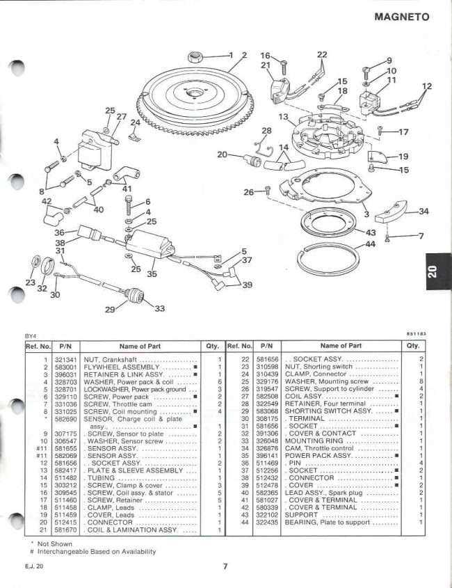
The power supply unit is responsible for converting and distributing electrical energy throughout the system. It ensures that each component receives the necessary voltage and current, playing a vital role in the overall performance and reliability.
Ignition System
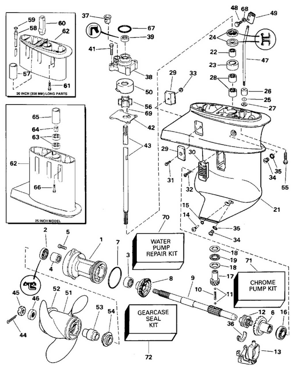
The ignition system initiates the combustion process by creating a spark at the appropriate moment. Its efficiency directly impacts the engine’s starting capability and operational stability, making it a critical component for optimal performance.
Understanding the Cooling System Layout
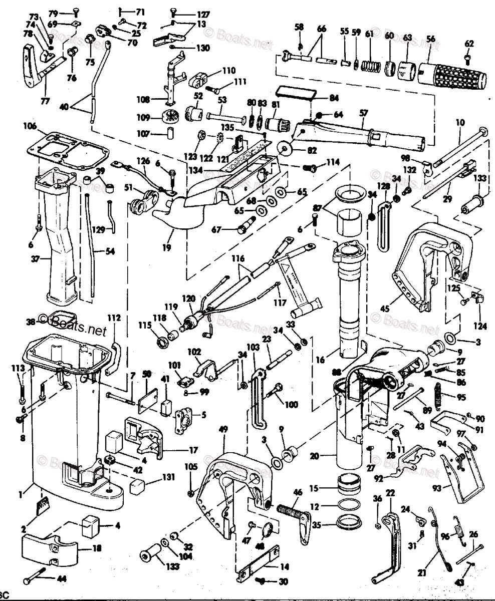
The cooling system is a crucial component in maintaining optimal operating temperatures for various machinery. Its design is meticulously planned to ensure effective heat dissipation and prevent overheating, thereby enhancing overall performance and longevity. A comprehensive understanding of this layout is essential for effective maintenance and troubleshooting.
This system typically comprises several interconnected elements, including the radiator, water pump, and hoses. Each part plays a significant role in circulating coolant throughout the engine, absorbing excess heat and transferring it to the radiator, where it is dissipated into the air. Understanding how these components interact helps in diagnosing issues related to overheating and coolant leaks.
Regular inspection of the cooling system layout can reveal potential problems before they escalate. Ensuring that all connections are secure, and hoses are free of cracks or leaks is vital. Additionally, maintaining proper coolant levels and checking for any blockages within the radiator can significantly enhance system efficiency and reliability.
Carburetor Components and Functions
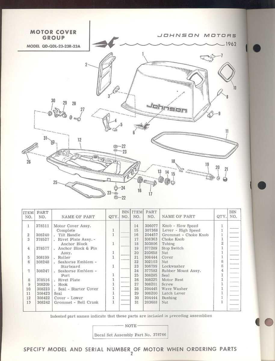
The carburetor plays a vital role in the overall performance of an engine, blending air and fuel in the appropriate ratio for efficient combustion. Understanding its components is essential for maintenance and troubleshooting.
Main components of the carburetor include the float chamber, jet, and throttle valve. The float chamber maintains a consistent fuel level, while the jet controls the flow of fuel into the air stream. The throttle valve regulates the engine’s power output by controlling the amount of air entering the combustion chamber.
Each part serves a specific function. The float chamber ensures that the engine receives a steady supply of fuel, preventing fluctuations that could affect performance. The jet’s design affects how fuel mixes with air, impacting efficiency and emissions. Lastly, the throttle valve directly influences the engine’s responsiveness, enabling smooth acceleration and deceleration.
Regular inspection and maintenance of these components are crucial to ensure optimal operation. Keeping them in good condition helps maintain performance and extends the lifespan of the engine.
Exhaust System Structure Explained
The exhaust system plays a crucial role in the overall performance and efficiency of a marine engine. It is designed to safely channel combustion gases away from the engine, ensuring optimal operation while minimizing noise and emissions. Understanding the components and their functions is essential for maintenance and troubleshooting.
Typically, the exhaust system consists of several key elements:
- Exhaust Manifold: This component collects exhaust gases from the engine cylinders and directs them into the exhaust piping.
- Exhaust Pipes: These pipes transport the gases away from the manifold, often incorporating bends and turns to fit the engine layout.
- Water Injection System: In many configurations, water is introduced into the exhaust system to cool the gases, reducing heat and preventing damage to components.
- Muffler: This part is crucial for noise reduction, helping to quiet the sound produced by the engine while allowing gases to exit freely.
- Outlet: The final exit point for exhaust gases, which ensures they are expelled safely into the environment.
Each of these components works together to maintain the engine’s efficiency and protect its integrity. Regular inspection and maintenance of the exhaust system are vital to prevent blockages, leaks, and other issues that could impair performance.
Ignition System Parts and Configuration
The ignition mechanism is a crucial component that ensures the effective initiation of the combustion process in an engine. It comprises several elements that work in harmony to generate the necessary spark, enabling the engine to run smoothly. Understanding the individual components and their arrangement is essential for maintenance and troubleshooting.
Key Components of the Ignition Mechanism
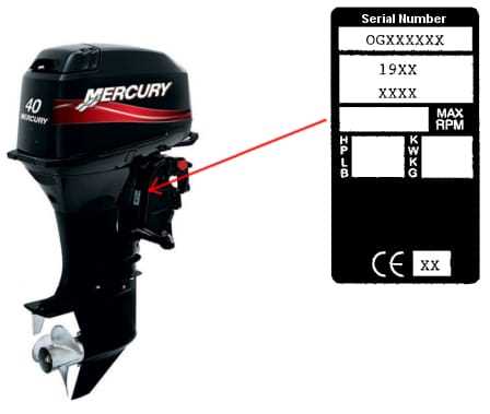
Several critical components play significant roles in the ignition system. These include the coil, distributor, spark plugs, and associated wiring. Each part has its specific function, contributing to the overall effectiveness of the system.
| Component | Function |
|---|---|
| Ignition Coil | Transforms low voltage to high voltage to create a spark. |
| Distributor | Directs high voltage from the ignition coil to the correct spark plug. |
| Spark Plug | Ignites the air-fuel mixture by creating a spark. |
| Wiring Harness | Connects all electrical components, ensuring effective communication. |
Configuration and Setup
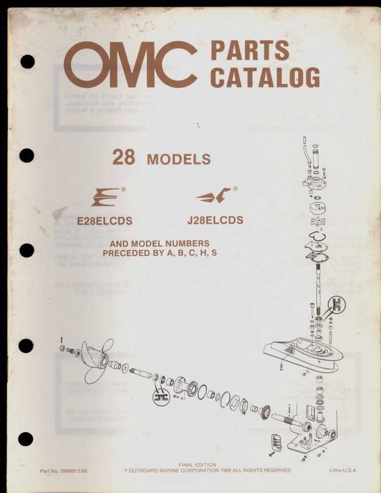
Proper configuration of the ignition system is vital for optimal engine performance. Each component must be accurately positioned and securely connected to ensure efficient spark generation. Regular checks and adjustments can help maintain the system’s integrity, preventing misfires and ensuring a reliable operation.
Propeller Assembly and Related Parts
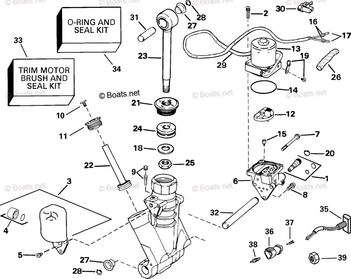
The assembly responsible for propulsion in watercraft is a critical component that significantly influences performance and efficiency. This section explores the various elements that constitute this assembly, highlighting their functions and importance in the overall operation of marine engines. Understanding these components can aid in effective maintenance and troubleshooting.
At the core of the propulsion system is the propeller, designed to convert rotational energy into thrust. Its shape and size play a crucial role in determining speed and maneuverability. Surrounding the propeller are several related components that ensure smooth operation, including the hub, which connects the propeller to the engine, and the shaft, which transmits power from the engine to the propeller.
Additionally, the assembly includes spacers and couplings, which are vital for proper alignment and stability during operation. Regular inspection and maintenance of these elements are essential to prevent performance issues and extend the lifespan of the propulsion system.
Gearbox Components and Their Role
The gearbox serves as a crucial element in various mechanical systems, facilitating the efficient transmission of power from the engine to the wheels. Understanding the various components within this assembly is essential for grasping how they work together to optimize performance.
Gears are the primary components that adjust the torque and speed. These toothed wheels mesh together to transfer rotational force, enabling the vehicle to accelerate or decelerate smoothly. The arrangement and size of these gears significantly influence the overall efficiency of the system.
Shafts play a vital role in connecting different elements within the gearbox. They transmit rotational motion from one component to another, ensuring that energy flows effectively throughout the assembly. The design of these shafts must withstand considerable stress during operation.
Bearings are critical for reducing friction between moving parts. By supporting the shafts and allowing them to rotate freely, they enhance the longevity and reliability of the gearbox. Proper lubrication is essential to maintain their performance and prevent wear.
Housings protect the internal components from external elements. They provide structural integrity and help contain the lubricants necessary for smooth operation. The design of these housings is crucial for maintaining the efficiency of the gearbox.
In summary, each component within the gearbox plays a specific role, working in unison to facilitate effective power transmission and enhance the overall functionality of the machinery.
Lubrication System in Johnson 115
The lubrication mechanism in marine engines plays a crucial role in maintaining optimal performance and extending the lifespan of various components. This system is designed to ensure that moving parts are adequately lubricated, reducing friction and wear. Proper maintenance of this system is essential for smooth operation and preventing potential damage.
The primary function of the lubrication system is to circulate oil throughout the engine, delivering it to critical areas such as bearings and gears. Oil pumps are responsible for drawing the lubricant from the reservoir and pushing it through filters and passages to the targeted regions. Regular checks on oil levels and quality are vital to ensure the system operates efficiently.
Moreover, the design of the lubrication system often incorporates various components such as filters, hoses, and coolers. These elements work together to maintain the integrity of the lubricant, ensuring it remains free from contaminants. Neglecting the lubrication system can lead to severe issues, including overheating and component failure.