Understanding the Components of Use Case Diagrams
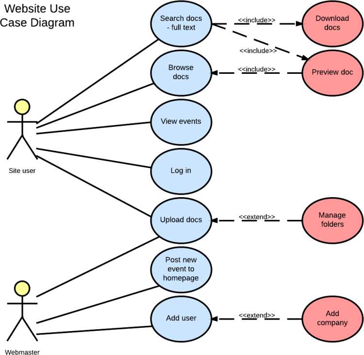
In the realm of system design, a visual representation serves as a powerful tool for conveying the intricate relationships and functionalities of a system. This approach aids stakeholders in understanding how different components interact with each other and the roles that users play within this framework. By illustrating these dynamics, clarity and insight are achieved, enhancing communication among project members.
Every illustration comprises various components, each fulfilling a distinct role in the overall narrative. These elements help in outlining not only the interactions that occur but also the expectations and objectives tied to user engagement. Recognizing these fundamental pieces allows for a more comprehensive grasp of how a system operates and responds to different scenarios.
Through careful examination of these individual components, one can appreciate how they collectively contribute to a cohesive representation of functionality. This exploration reveals the underlying structure that drives user experiences and guides the design process, ensuring that all needs are addressed effectively.
Understanding Use Case Diagrams
Visual representations play a crucial role in grasping the interactions within systems. By illustrating various elements and their relationships, these models provide clarity and insight into how users engage with functionalities. This section aims to explore these visual tools and their significance in system analysis.
Key Components
- Actors: Represent external entities that interact with the system.
- Actions: Depict the tasks performed by the actors.
- Boundaries: Define the limits of the system being analyzed.
Benefits of Visual Models
- Enhance communication among stakeholders.
- Facilitate better understanding of user requirements.
- Assist in identifying potential issues early in development.
Key Components of Use Case Diagrams
Understanding the essential elements that compose a visual representation of interactions is crucial for effective communication among stakeholders. Each component plays a vital role in illustrating how various entities interact within a system, facilitating clarity and comprehension.
Actors
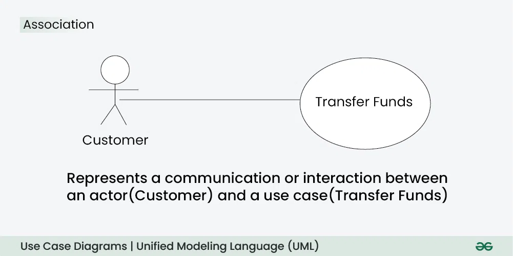
Actors represent the entities that interact with the system. They can be:
- Users
- External systems
- Administrators
Actions
Actions illustrate the functions or services provided by the system. Key types include:
- Basic actions: Core functionalities
- Alternative actions: Conditional processes
- Composite actions: Grouped functionalities
Actors in Use Case Diagrams
In the realm of system modeling, certain entities interact with the system to achieve specific goals. These entities play a crucial role in defining how users engage with the functionalities provided by the system. Understanding their characteristics helps clarify system requirements and user expectations.
Types of Actors
- Primary Actors: These are individuals or systems that directly initiate interactions to fulfill a goal.
- Secondary Actors: Entities that provide support or services to the primary actors during their interactions.
Identifying Actors
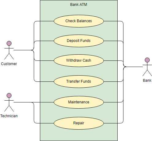
- Analyze system requirements to determine who will interact with it.
- Consider both human users and external systems that may affect or be affected by the system.
- Document each actor’s goals and how they relate to system functionality.
Defining Use Cases Effectively
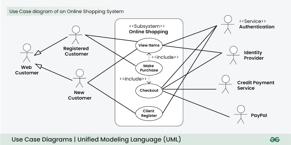
Creating well-structured scenarios is essential for understanding system requirements and user interactions. By outlining these scenarios clearly, teams can ensure that all stakeholders share a common vision, leading to improved communication and more efficient development processes.
Understanding User Needs
To craft effective scenarios, it’s crucial to identify and analyze the needs of end users. Engaging directly with users through interviews or surveys can provide invaluable insights, helping to create relevant narratives that resonate with real-world applications.
Detailing Interactions
Once user needs are established, the next step involves elaborating on interactions. Each narrative should encompass a clear sequence of actions, outlining goals and potential challenges. Clarity in these descriptions not only enhances comprehension but also serves as a reference throughout the development lifecycle.
Relationships Between Actors and Use Cases
The interaction between participants and functional scenarios is a fundamental aspect of system design. Understanding how these entities relate to one another helps clarify requirements and improve communication among stakeholders.
These interactions can be categorized into several types, each highlighting a different facet of their relationship:
- Association: This represents a direct link between a participant and a functional scenario, indicating that the participant engages with the scenario.
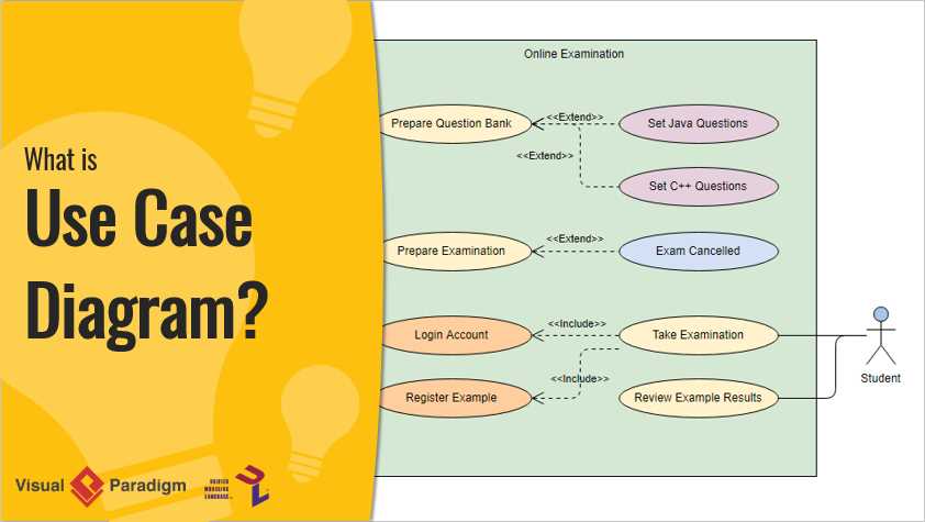
- Include: This denotes a scenario that is a necessary component of another, allowing for shared functionality and reducing redundancy.
- Extend: This illustrates optional behavior that can enhance a primary scenario, providing additional features when certain conditions are met.
- Generalization: This involves a hierarchy where a more general participant can inherit behaviors from a more specific one, facilitating a clearer structure in roles and functionalities.
Each type of interaction serves a unique purpose in defining the dynamics between participants and functional scenarios, contributing to a comprehensive understanding of system behavior.
System Boundaries in Use Case Diagrams
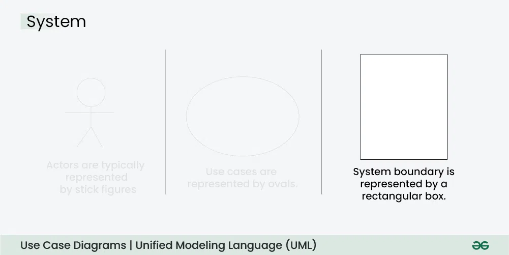
Defining the limits of a system is crucial in understanding its interactions with external entities. These boundaries help clarify what functionalities are included within the system and which ones reside outside its scope.
Establishing these boundaries allows stakeholders to:
- Identify interactions between users and the system.
- Differentiate between essential functions and external influences.
- Focus on system requirements without ambiguity.
When delineating boundaries, consider the following:
- Assess the core functionalities that the system will deliver.
- Recognize external actors that will interact with the system.
- Ensure clarity in the documentation for all stakeholders involved.
Ultimately, clear boundaries lead to a more focused and effective design process, facilitating better communication among teams and stakeholders alike.
Types of Use Case Relationships
In the realm of modeling interactions, various connections exist that help clarify how different actions and roles interact with one another. These relationships serve as a framework to illustrate dependencies, hierarchies, and collaborations among distinct functionalities. Understanding these associations is crucial for accurately conveying the dynamics within a system.
There are primarily three kinds of relationships that are commonly recognized: association, inclusion, and extension. Each type plays a vital role in outlining how different functionalities relate to one another, enhancing the overall comprehension of system behavior.
Association signifies a direct link between an actor and a functionality, indicating the active engagement of users in executing specific tasks. This relationship is fundamental in establishing the core interactions within the system.
Inclusion represents a scenario where one action incorporates another, highlighting a mandatory dependency. This means that certain tasks cannot occur without invoking additional functionalities, ensuring that essential steps are consistently followed.
Extension, on the other hand, allows for optional behavior that supplements a primary action. This relationship provides flexibility, enabling the addition of extra functionalities that can enhance user experience without altering the core process.
By recognizing and utilizing these different types of relationships, stakeholders can create a more nuanced and comprehensive understanding of system interactions, ultimately leading to more effective designs and implementations.
Importance of Use Case Diagrams
Visual representations play a crucial role in software development, offering clarity and understanding of system interactions. They help stakeholders comprehend functional requirements and facilitate communication among various teams, ensuring that everyone shares a unified vision of the project goals.
Benefits of Visual Representations
- Enhanced Communication: These illustrations foster better dialogue between technical and non-technical stakeholders, bridging gaps in understanding.
- Clear Requirements: By outlining user interactions, they help identify and document functional requirements more effectively.
- Identifying Gaps: Visual models assist in spotting missing functionalities or potential issues before development begins.
Facilitating Development Process
- Guiding Development: They serve as a reference point for developers, ensuring alignment with user needs throughout the project.
- Testing and Validation: These representations aid in creating test cases, validating that the final product meets user expectations.
- Documentation: They contribute to project documentation, making it easier for future teams to understand system functionality.
Common Mistakes in Use Case Diagrams
In the realm of visual representation for system interactions, several pitfalls can hinder clarity and effectiveness. These errors often stem from misunderstandings or oversights that compromise the overall quality and utility of the depiction.
1. Overcomplicating Scenarios: It’s easy to fall into the trap of adding excessive detail. Keeping interactions simple ensures that the essence of each scenario remains clear.
2. Neglecting Stakeholders: Failing to identify all relevant actors can lead to an incomplete understanding of the system’s requirements. Each participant’s role should be explicitly defined.
3. Inconsistent Naming Conventions: Using varied terminology for similar elements can confuse viewers. Consistency in labels promotes better comprehension.
4. Ignoring Relationships: Not properly illustrating connections between elements can obscure how different parts interact. Clearly defining relationships enhances overall understanding.
5. Lack of Validation: Skipping the review process can result in unnoticed flaws. Engaging stakeholders in validation ensures accuracy and alignment with actual needs.
Best Practices for Creating Diagrams
Effective visual representations are essential for clear communication and understanding. Adopting best practices can significantly enhance the quality and impact of your illustrations, ensuring they convey the intended message efficiently.
| Practice | Description |
|---|---|
| Clarity | Ensure elements are easily distinguishable and labeled appropriately to avoid confusion. |
| Simplicity | Avoid overcrowding; focus on essential components to maintain readability. |
| Consistency | Use uniform symbols and colors throughout to create a cohesive look. |
| Alignment | Organize elements logically to guide the viewer’s eye smoothly across the visual. |
| Feedback | Solicit input from peers to identify potential improvements or ambiguities. |
Tools for Designing Use Case Diagrams
Creating visual representations of system interactions requires specialized instruments that facilitate clarity and organization. These applications provide essential features that simplify the process of capturing user requirements and system behaviors effectively.
| Tool | Description | Key Features |
|---|---|---|
| Lucidchart | A cloud-based platform that allows for collaborative diagramming. | Real-time collaboration, templates, and easy sharing. |
| Microsoft Visio | A robust desktop application for creating various types of visual models. | Extensive shapes library, integration with Microsoft Office, and data linking. |
| Draw.io | An open-source tool for designing diagrams directly in a web browser. | User-friendly interface, free to use, and supports various file formats. |
| StarUML | A powerful modeling tool for software architecture. | Support for UML standards, extensibility through plugins, and export options. |