2009 Honda Civic Parts Diagram Overview
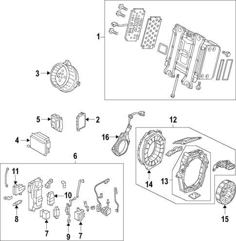
2009 honda civic parts diagram

Understanding the layout and configuration of essential mechanical elements is crucial for both maintenance and repair. Each section of a vehicle relies on the correct positioning and connection of various elements, working in unison to ensure smooth performance and reliability.

Having a clear reference to the structure and placement of these components can help identify the cause of potential issues and allow for quick and efficient troubleshooting. This guide offers insight into how different elements are interconnected within the engine, transmission, and other vital systems.

Whether you’re looking to replace worn-out pieces or upgrade specific areas, a detailed look at the arrangement of mechanical and electrical components will prove invaluable for proper installation and adjustments. This overview is designed to assist in locating each critical part to facilitate optimal operation and longevity.

2009 Honda Civic Component Layout Overview

2009 honda civic parts diagram

The layout of key mechanical and electrical elements in this vehicle is thoughtfully designed to ensure accessibility and functionality. Each section is strategically organized to facilitate maintenance and optimize overall performance.

  • Engine Bay: A central feature housing various essential systems, including fluid reservoirs and key mechanical components.
  • Interior Console: The internal layout features easy access to critical controls, ensuring a user-friendly experience for drivers and passengers.
  • Undercarriage: This area provides structural support and protection for important elements beneath the frame.

Each of these areas contains carefully placed components, ensuring smooth operation and straightforward maintenance when needed.

Engine Bay Parts Identification

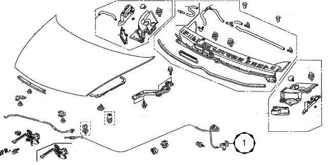
The engine bay houses several essential components that work together to ensure the vehicle operates smoothly. Understanding the location and function of each part is crucial for maintaining and troubleshooting the system. This section provides a clear overview of key elements located under the hood, aiding in proper identification and comprehension of their roles.

Brake System Components Explained

Understanding the key elements of the braking mechanism is essential for maintaining vehicle safety and performance. The system includes multiple components that work together to ensure proper deceleration and stopping force. This section covers the fundamental elements and their functions, helping to clarify how the entire setup operates efficiently.

Primary Components

2009 honda civic parts diagram

The braking assembly consists of several main parts, each playing a crucial role in controlling the vehicle’s movement. These include the elements responsible for generating, transferring, and applying force to the wheels.

Component Description
Cooling System Responsible for regulating the temperature of the engine to prevent overheating and maintain optimal performance.
Intake System Facilitates the flow of air into the engine for combustion, improving fuel efficiency and power output.
Battery Supplies electrical power to start the vehicle and supports various electronic systems when the engine is off.
Transmission Transfers the engine’s power to the wheels, allowing the vehicle to move at different speeds and torque levels.
Component Description
Brake Pedal The device that initiates the braking process when pressure is applied by the driver.
Master Cylinder Converts the force from the pedal into hydraulic pressure, which is then distributed to the rest of the system.
Brake Lines These tubes carry the hydraulic fluid from the master cylinder to the braking mechanisms at each wheel.
Brake Calipers They

Suspension Elements and Their Placement

The arrangement of key components responsible for absorbing road impact and maintaining vehicle stability plays a critical role in ensuring a smooth and safe ride. These elements work together to provide a balance between comfort and handling, responding to various driving conditions and terrain types. Understanding their positioning and function is essential for proper maintenance and optimal performance.

Main Components

Several vital components are involved in this system. These include shock absorbers, which reduce the impact of road irregularities, and control arms that help guide the wheel’s motion. Together, they form a complex structure that enhances both comfort and control.

Placement and Functionality

Each component is strategically placed to handle specific loads and forces. For example, the springs are positioned to bear the weight of the vehicle, while the stabilizer

Interior Equipment and Controls Mapping

The layout of the vehicle’s cabin is designed to ensure easy access to essential controls and features, promoting convenience and safety for both the driver and passengers. Understanding the arrangement of various interior components allows for efficient use of the system during operation.

Electrical System Wiring Overview

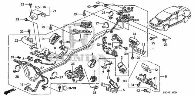
The electrical framework of a vehicle serves as the backbone for powering various essential components. From the lights to the ignition system, the wiring network ensures a seamless flow of electricity to all crucial elements. Understanding how these wires are arranged and how they interact with each other is key to maintaining the proper functionality of the vehicle.

Proper connections between the various segments of the wiring system are crucial to prevent malfunctions. Any disruption in this network can lead to performance issues, safety risks, or even damage to key systems. Knowing the layout and routing of wires allows for easier troubleshooting and more efficient repairs.

Fuel System Parts and Connections

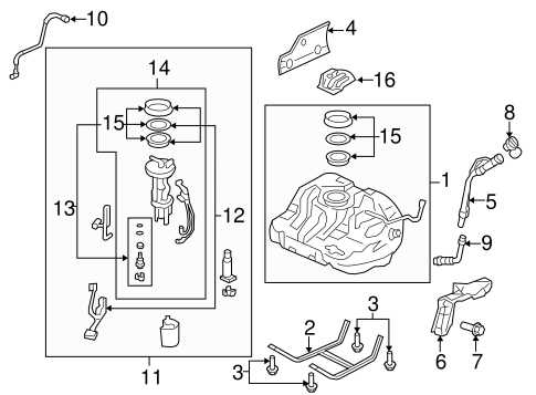
The fuel system is a critical network that ensures the proper flow and distribution of fuel to the engine. This section covers the key elements involved in delivering the necessary fuel for smooth engine operation. Each component, from storage to the engine’s internal mechanisms, plays a role in maintaining efficiency and performance.

Pumps and lines work together to transfer fuel from the storage area to the combustion chambers, ensuring continuous flow. Along the way, various filters and regulators help manage pressure and purity, protecting the engine from contaminants and ensuring optimal fuel delivery.

Connections between these components are carefully engineered to maintain a sealed environment, preventing leaks and maintaining consistent fuel pressure. Proper maintenance and regular inspections of these links are essential to avoid disruptions in the system’s operation.

Transmission Diagram and Key Elements

The transmission system plays a crucial role in ensuring smooth power delivery from the engine to the wheels, enabling seamless gear shifting and efficient vehicle operation. It consists of several interconnected components that work together to optimize performance under different driving conditions.

Key elements of the transmission system include the clutch, gears, and shafts. Each of these parts is designed to handle specific functions, such as transferring torque, managing speed, and ensuring the smooth engagement of gears. Understanding these elements is essential for maintaining the system’s longevity and functionality.

Additional components such as synchronizers and shift mechanisms also contribute to the system’s ability to function efficiently, allowing for precise control and minimizing wear during gear changes.

Exhaust System Layout Breakdown

2009 honda civic parts diagram

The exhaust system plays a crucial role in a vehicle’s performance, facilitating the efficient expulsion of gases produced during combustion. Understanding the layout of this system can provide insights into its function and potential areas for improvement. This section will delve into the components and their arrangement, highlighting their significance in the overall mechanism.

Key Components of the Exhaust Assembly

At the heart of the exhaust assembly lies the manifold, which collects gases from the engine and directs them toward the rest of the system. Following the manifold is the catalytic converter, designed to reduce harmful emissions through chemical reactions. Another critical part is the resonator, which minimizes noise while maintaining optimal airflow. Finally, the exhaust pipe carries the treated gases away from the vehicle.

Flow Path and Efficiency

The arrangement of these components is engineered to promote efficient gas flow, reducing back pressure and enhancing engine performance. Each segment must be carefully aligned to ensure proper connectivity, allowing gases to exit seamlessly. Any obstruction or misalignment can lead to reduced efficiency, impacting both performance and fuel economy.

Cooling System and Radiator Setup

The cooling mechanism in a vehicle plays a vital role in maintaining optimal engine temperatures, ensuring efficient performance and longevity. This section outlines the essential components involved in the cooling system, including the configuration of the radiator and associated parts that contribute to temperature regulation.

The radiator serves as a crucial element, facilitating the transfer of heat away from the engine. As coolant circulates through the engine, it absorbs heat, which is then released into the atmosphere via the radiator. The effectiveness of this system relies on various components working in harmony.

Component Location Function
Steering Wheel Controls Center of the dashboard Adjust audio settings, navigate menus, and activate hands-free communication.
Climate Control Panel Center console Regulates the temperature, airflow, and air conditioning system.
Infotainment Screen Above the central vents Provides navigation, entertainment, and vehicle information displays.
Component Description
Radiator A heat exchanger that dissipates heat from the engine coolant to the air.
Water Pump Circulates coolant throughout the engine and radiator, maintaining flow.
Thermostat Regulates coolant flow based on engine temperature, ensuring optimal heating.
Coolant Reservoir Stores excess coolant and allows for expansion as temperatures fluctuate.
Cooling Hoses Flexible tubes that transport coolant to and from the engine and radiator.

Understanding the interplay between these components is essential for troubleshooting issues related to overheating and coolant leaks. Regular maintenance of the cooling assembly ensures the engine operates within a safe temperature range, preventing damage and enhancing performance.

Air Conditioning and HVAC Components

2009 honda civic parts diagram

In modern vehicles, maintaining a comfortable environment is crucial, and the climate control system plays a vital role in achieving this. This system consists of various elements that work together to regulate temperature, humidity, and air quality inside the cabin. Understanding these components can enhance the efficiency of the system and aid in troubleshooting any issues that may arise.

  • Compressor: This component compresses refrigerant gas and circulates it throughout the system, ensuring proper cooling.
  • Condenser: Located at the front of the vehicle, the condenser cools the refrigerant, converting it from gas to liquid.
  • Evaporator: Positioned inside the cabin, the evaporator absorbs heat from the air, allowing the cooled air to enter the passenger area.
  • Expansion Valve: This device regulates the flow of refrigerant into the evaporator, maintaining the correct pressure and temperature.
  • Blower Motor: This component circulates air within the cabin, enabling the desired temperature settings to be achieved quickly.
  • Climate Control Module: An electronic unit that manages the operation of the HVAC system, adjusting settings based on user input and sensor readings.

Each of these components plays a significant role in ensuring optimal performance of the climate control system. Regular maintenance and inspections can prevent potential failures and enhance the longevity of the entire system.

Body Panels and Exterior Trim

2009 honda civic parts diagram

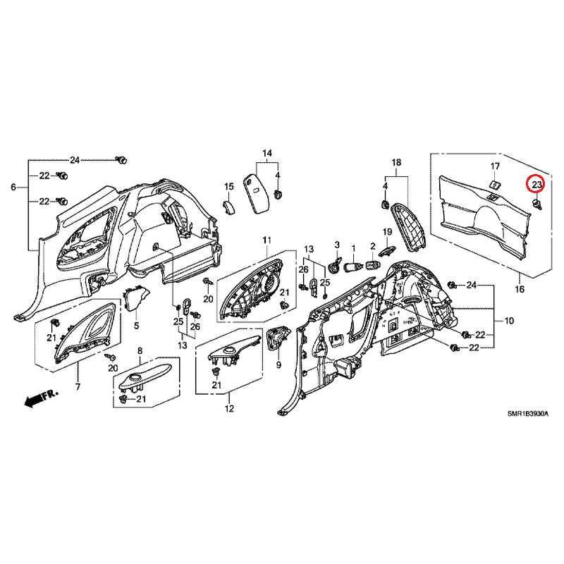
The external components of a vehicle play a crucial role in both aesthetics and functionality. These elements not only define the overall look of the automobile but also serve to protect internal mechanisms and improve aerodynamic performance. Understanding the various parts that make up the outer shell is essential for maintenance and repair.

Key Components

  • Fenders: These are located over the wheels and help prevent debris from being thrown into the air.
  • Hood: The cover that rests over the engine compartment, designed for access and protection.
  • Doors: Provide access to the cabin and enhance safety features.
  • Trunk Lid: Covers the storage area at the rear, providing both security and access.
  • Bumpers: Designed to absorb impact and protect the body from damage during collisions.

Exterior Trim Elements

  1. Grille: Allows airflow to the engine while adding to the vehicle’s style.
  2. Moldings: Decorative strips that enhance the visual appeal and can protect against minor dings.
  3. Mirrors: Essential for visibility, these come in various styles and often include electrical components.
  4. Lights: Front and rear lighting not only provide visibility but also contribute to safety regulations.
  5. Windshield: A critical safety component that provides visibility and structural support.

Maintaining these exterior features is vital for both the performance and appearance of the vehicle. Regular inspections can help identify wear and tear, ensuring longevity and safety.

Lighting and Signal Components Diagram

This section explores the various elements associated with illumination and signaling systems in vehicles. Understanding the configuration of these components is crucial for maintaining optimal visibility and ensuring safe communication with other road users. Each element serves a specific function, contributing to the overall performance of the vehicle’s lighting system.

Key Components

  • Headlights: Essential for nighttime driving, providing illumination ahead.
  • Turn Signals: Indicate directional intentions to other drivers.
  • Brake Lights: Alert vehicles behind when the driver applies the brakes.
  • Reverse Lights: Illuminate the area behind the vehicle when reversing.
  • Fog Lights: Improve visibility in adverse weather conditions.

Functional Relationships

Each component interacts with others to create a cohesive lighting system. Understanding these relationships enhances the ability to diagnose issues and perform effective repairs.

  • Headlights and fog lights often share wiring connections.
  • Turn signals may be integrated with the brake light system for efficiency.
  • Signal activation mechanisms can influence multiple light functions.