Complete Guide to John Deere 50G Parts Diagram
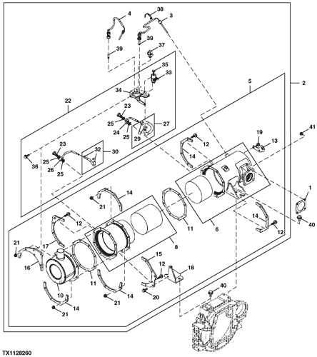
The intricate workings of construction machinery often hinge on a well-organized structure of components. Each element plays a crucial role in ensuring optimal performance and efficiency, making it essential for operators and technicians to have a clear understanding of how these pieces fit together.
Exploring the layout of various sections can significantly aid in troubleshooting and maintenance. By visualizing the arrangement of each constituent part, one can quickly identify issues, streamline repairs, and enhance overall functionality. This knowledge not only empowers professionals in the field but also contributes to the longevity of the equipment.
In this discussion, we will delve into the comprehensive illustrations that outline the configuration of essential components. Such insights are invaluable for anyone seeking to optimize their machinery’s operation and uphold safety standards in the demanding environments where they are utilized.
Understanding John Deere 50G Parts
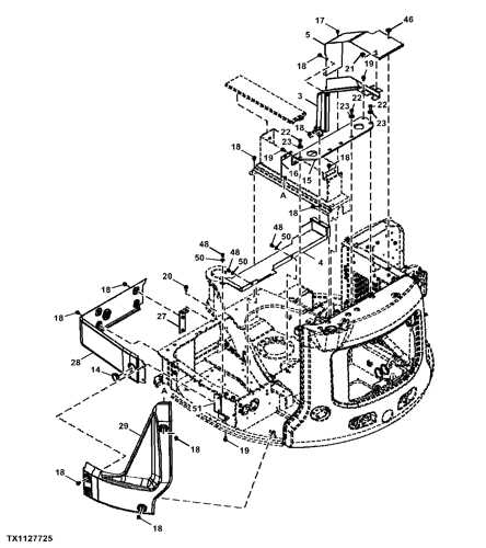
Comprehending the various components of a specific machinery model is essential for effective maintenance and operation. Familiarity with the individual elements enhances performance, ensures longevity, and facilitates easier repairs. This knowledge allows operators to tackle issues proactively and improve overall efficiency.
Key Components
- Engine Assembly
- Hydraulic System
- Transmission
- Undercarriage
- Cab Structure
Maintenance Tips
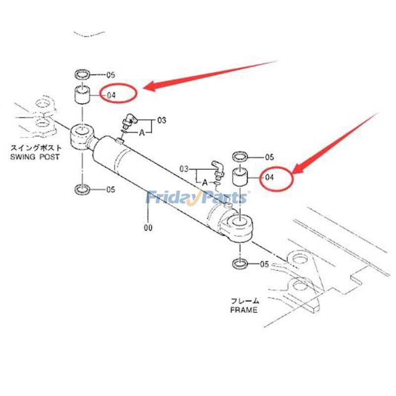
- Regularly check fluid levels to prevent overheating.
- Inspect hydraulic hoses for wear or leaks.
- Clean air filters to ensure optimal engine performance.
- Examine undercarriage components for wear and tear.
- Follow manufacturer guidelines for part replacements.
Understanding these essential elements not only aids in troubleshooting but also empowers operators to maximize the functionality of their equipment, ensuring a productive work environment.
Overview of the 50G Model
The 50G model represents a significant advancement in compact machinery, designed to excel in various applications. This versatile equipment is engineered for efficiency and precision, catering to the needs of professionals in construction and landscaping. Its compact size allows for maneuverability in tight spaces while maintaining robust performance characteristics.
Key Features
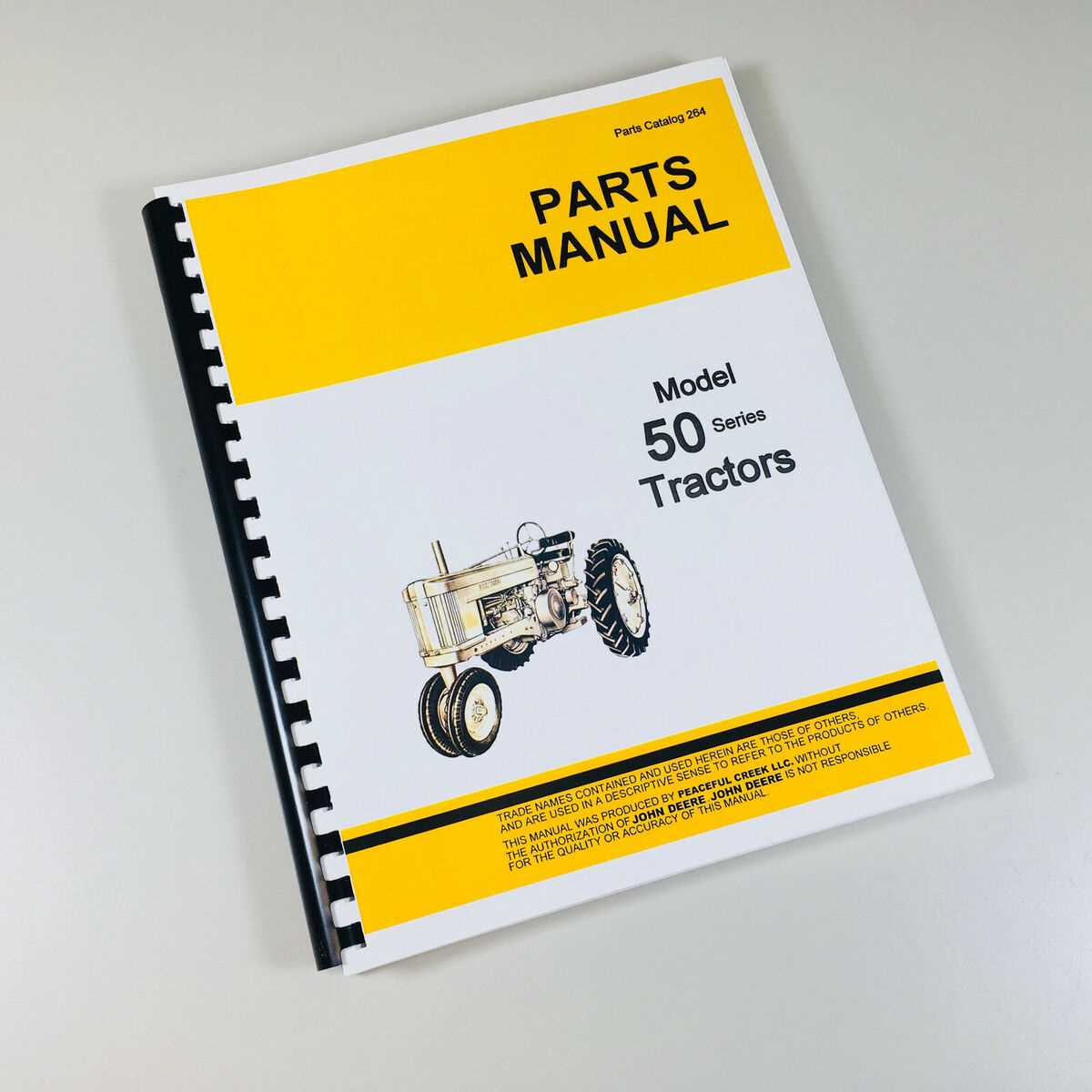
One of the standout aspects of this model is its powerful engine, which ensures reliable operation under diverse conditions. Additionally, its hydraulic system is optimized for effective lifting and digging capabilities, enhancing productivity on the job site. The ergonomic design contributes to operator comfort, allowing for extended use without fatigue.
Applications
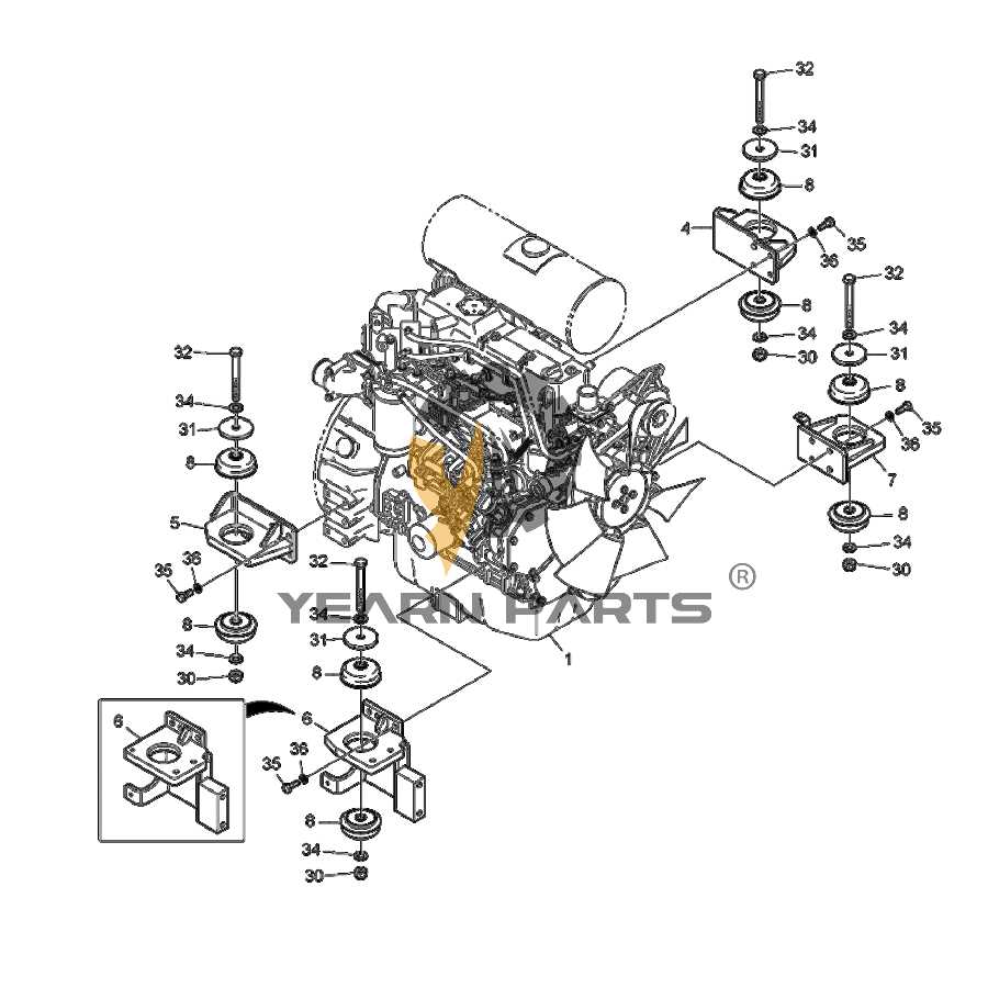
Due to its adaptability, this model is well-suited for a variety of tasks, from trenching and grading to site preparation and utility work. The ability to switch attachments quickly further extends its functionality, making it an essential tool for contractors and landscapers alike. Overall, this machine embodies a perfect blend of power, versatility, and user-friendliness.
Key Components Explained
This section provides an overview of essential elements that contribute to the functionality and efficiency of machinery. Understanding these components is crucial for effective maintenance and operation.
Hydraulic System: The hydraulic system is a vital part, responsible for powering various attachments and controlling movement. It utilizes fluid to transmit force, enabling precise operations.
Engine: The engine serves as the powerhouse, converting fuel into mechanical energy. Its performance directly impacts the overall capability of the machine, making regular checks important.
Undercarriage: The undercarriage supports the entire structure and facilitates mobility. Components such as tracks or wheels play a significant role in stability and traction on diverse terrains.
Operator Controls: Controls are essential for guiding the machine’s actions. An intuitive layout enhances efficiency, allowing operators to perform tasks with precision and ease.
Frame: The frame provides structural integrity, ensuring all parts remain aligned and functioning effectively. A robust frame can withstand heavy loads and challenging conditions.
By delving into these core components, users can enhance their understanding and ultimately improve the performance of their machinery.
Importance of Accurate Diagrams
Precision in visual representations is crucial for effective maintenance and repair tasks. Detailed illustrations serve as essential guides, ensuring that each component is properly identified and understood. This clarity not only aids technicians in performing their duties but also enhances overall efficiency and safety in operations.
Accurate visual aids minimize the risk of errors during assembly or disassembly processes. When individuals have access to well-structured representations, they can easily locate parts and comprehend their functions. This understanding fosters a systematic approach, reducing the likelihood of miscommunication or confusion.
| Benefits | Impact |
|---|---|
| Enhanced Clarity | Improved understanding of component relationships |
| Reduced Errors | Minimized risk of incorrect installations |
| Time Efficiency | Faster troubleshooting and repairs |
| Increased Safety | Lower risk of accidents due to misplacement |
In summary, well-crafted visual resources play a vital role in ensuring effective maintenance practices. By providing clear, detailed information, these representations support technicians in their tasks, ultimately leading to better performance and safety in operations.
How to Read Parts Diagrams
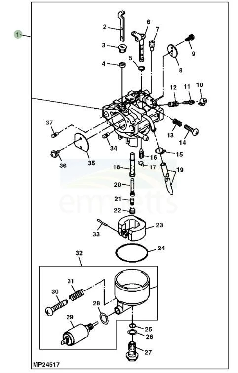
Understanding visual schematics can significantly enhance your ability to maintain and repair machinery. These illustrations serve as essential tools that provide insights into the various components and their interconnections within a machine. Mastering how to interpret these visuals will empower you to identify parts, troubleshoot issues, and streamline the repair process.
1. Familiarize Yourself with the Legend: Most schematics include a legend or key that explains the symbols used. Take time to review this section, as it will clarify what each symbol represents and how it relates to the overall system.
2. Identify the Layout: Examine the overall layout of the illustration. Components are typically organized in a way that reflects their physical arrangement within the machinery. Recognizing the spatial relationships can help you visualize how each element fits into the assembly.
3. Trace Connections: Pay attention to lines and arrows that indicate connections or pathways between components. These indicators can show how elements interact, helping you understand the flow of operations or signals.
4. Cross-Reference with Documentation: Use additional manuals or guides that describe the system in detail. Cross-referencing these documents with the visual representation can provide deeper insights and enhance your understanding of specific parts.
5. Take Notes and Sketch: As you study the illustration, consider taking notes or making your own sketches. This practice can reinforce your learning and provide a quick reference when working on the machine.
By following these steps, you’ll develop a clearer comprehension of how to navigate these valuable tools, ultimately leading to more efficient maintenance and repair work.
Common Issues with 50G Parts
When it comes to heavy machinery components, certain challenges frequently arise that can impact performance and longevity. Understanding these issues is crucial for maintaining operational efficiency and preventing costly downtime.
Wear and Tear
Over time, components experience natural degradation due to regular use. This wear can lead to reduced efficiency and potential failure if not addressed promptly.
Compatibility Concerns
Finding suitable replacements can be problematic, as not all components are universally compatible. Mismatched parts can result in improper function and increased wear on adjacent systems.
Where to Find Replacement Parts
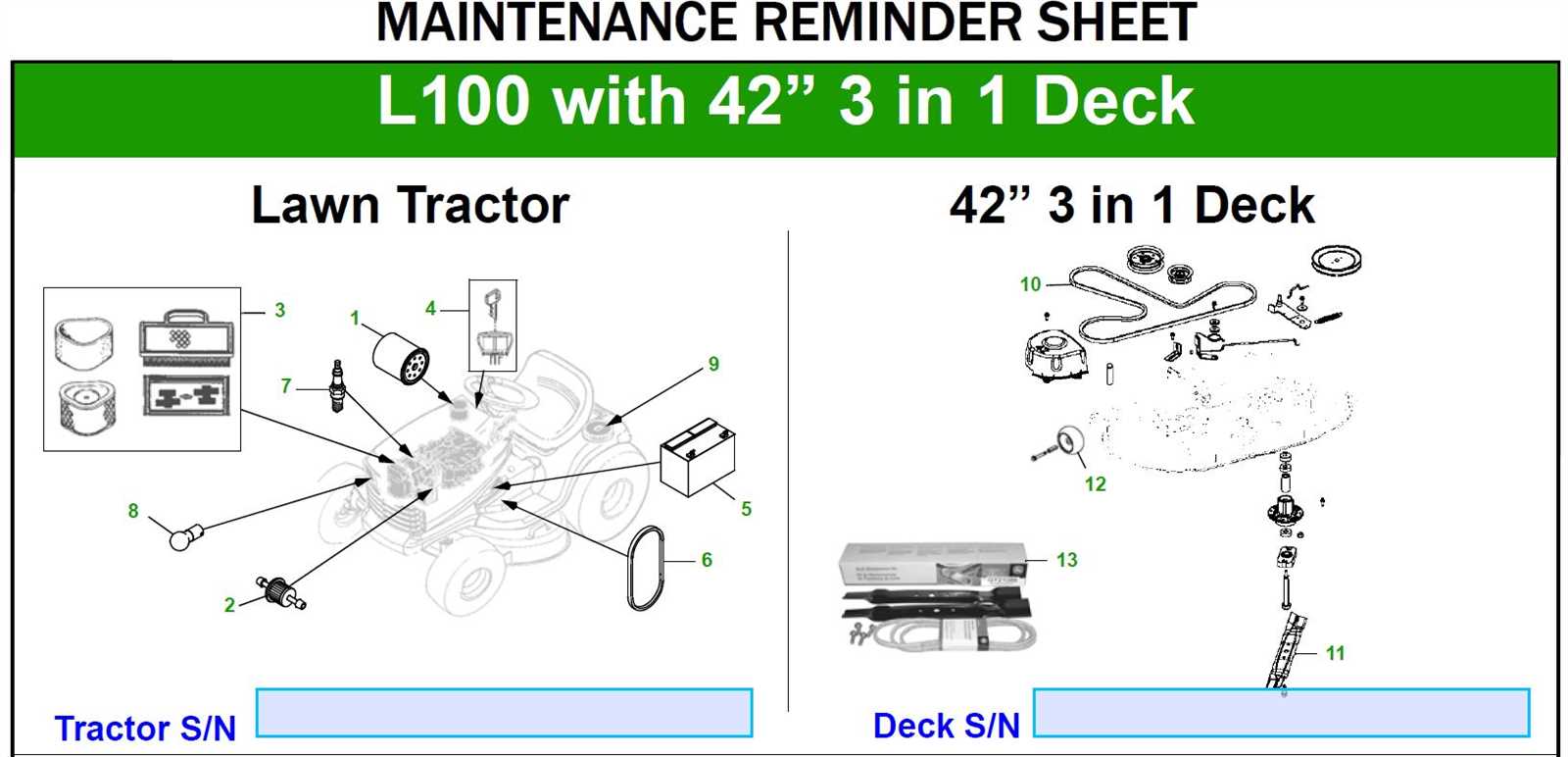
Locating suitable components for machinery can often be a daunting task, yet several reliable avenues can facilitate this process. Whether seeking original equipment or high-quality alternatives, understanding where to search is essential for efficient repairs.
Online marketplaces, specialized retailers, and manufacturer websites typically offer an extensive selection. Utilizing platforms dedicated to construction equipment can yield both new and used options, often at competitive prices. Additionally, joining forums or community groups related to heavy machinery can provide insights and recommendations from experienced users.
Local dealerships often carry a range of items, and their staff can assist in identifying specific needs based on your machine’s model. Furthermore, consulting service manuals can enhance your search, ensuring you acquire the correct replacements for seamless operation.
Maintenance Tips for Longevity
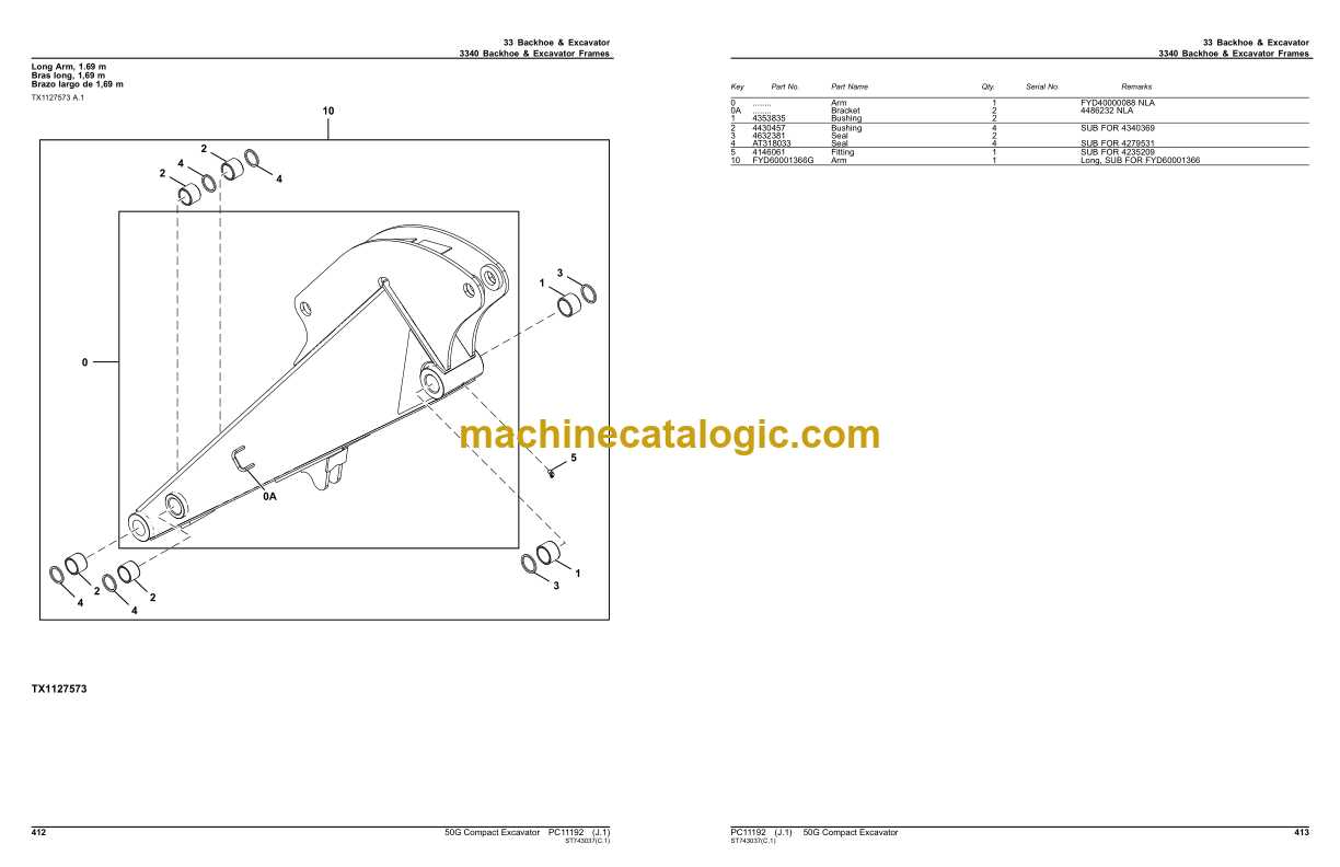
Ensuring the extended lifespan of your machinery requires diligent upkeep and regular care. By implementing proactive measures and monitoring key components, you can prevent premature wear and maintain optimal performance.
Regularly check fluid levels, including oil and coolant, to ensure they are within recommended ranges. This practice helps avoid overheating and engine damage.
Keep an eye on filters, replacing them as needed to maintain cleanliness and efficiency. Clogged filters can impede performance and lead to costly repairs.
Inspect belts and hoses for signs of wear or fraying. Addressing these issues early can prevent more serious breakdowns and extend the overall lifespan.
Finally, adhere to a scheduled maintenance routine, following the manufacturer’s guidelines. Consistency in care not only enhances performance but also ensures reliability in the long run.
Comparative Analysis with Other Models
This section delves into the key differences and similarities between various machinery models in the compact excavator category. By examining performance metrics, operational capabilities, and design features, we can better understand how these units stack up against one another in real-world applications.
Performance Metrics
When assessing operational efficiency, factors such as horsepower, digging depth, and lifting capacity play a crucial role. Many competitors in this segment may offer similar power outputs; however, variations in hydraulic systems can significantly affect overall performance. For instance, certain models may provide enhanced breakout forces, allowing operators to handle tougher tasks with ease.
Design and Ergonomics
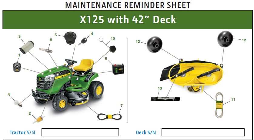
Another important aspect to consider is the design and user interface of the equipment. Comfort and ease of operation are paramount for long hours on the job site. While some models feature intuitive controls and spacious cabs, others may prioritize compactness and maneuverability. Operators should evaluate their specific needs to determine which design elements will best suit their workflow.
In summary, conducting a thorough comparative analysis allows potential buyers to make informed decisions based on their unique requirements and preferences.
Tools Required for Repairs
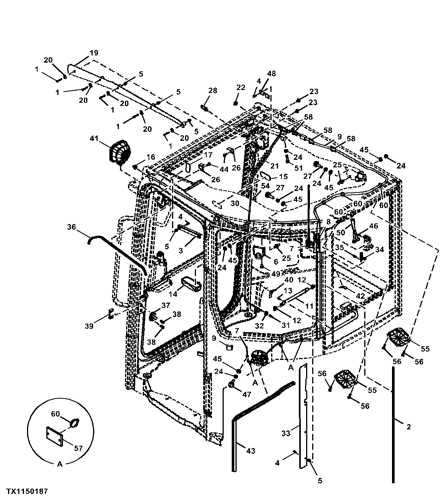
When undertaking maintenance or repairs on heavy machinery, having the right tools is essential for efficiency and safety. A well-equipped toolbox can make a significant difference in the quality of work and time spent on the task.
- Wrenches: Various sizes, including adjustable and socket types.
- Ratchet and Socket Set: Essential for loosening and tightening bolts.
- Screwdrivers: Both flathead and Phillips for different screws.
- Pliers: Needle-nose and standard for gripping and twisting.
- Hammer: A reliable tool for driving or adjusting components.
- Torque Wrench: Ensures bolts are tightened to the correct specifications.
- Measuring Tools: Calipers and rulers for precise measurements.
Having these tools readily available will streamline the repair process and help ensure that machinery operates at its ultimate efficiency.
Assembly Instructions for 50G Parts
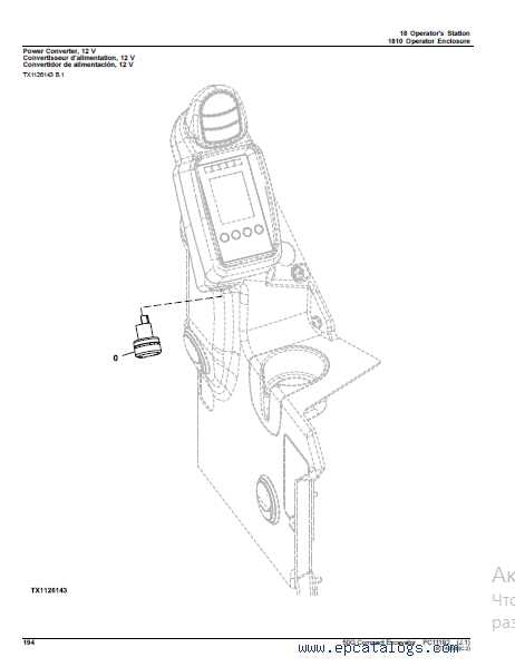
This section provides a comprehensive guide for the assembly process of essential components for the specified machine. Proper assembly ensures optimal performance and longevity of the equipment. Following these instructions will facilitate a smooth assembly experience, reducing the likelihood of errors and enhancing overall functionality.
Preparation Steps
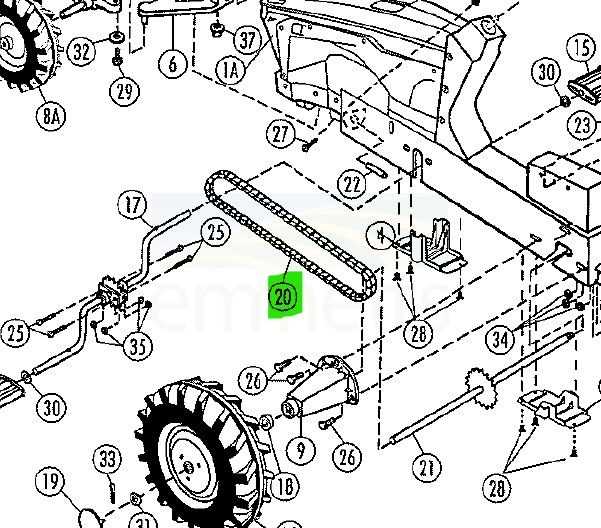
Before commencing the assembly, ensure all required components are available and in good condition. A clean workspace will help prevent contamination and damage to parts during the process. Additionally, gather all necessary tools to streamline the assembly procedure.
Assembly Process
Begin by identifying each component and its corresponding location. The following table outlines key components and their assembly order:
| Component | Assembly Order | Notes |
|---|---|---|
| Base Frame | 1 | Ensure alignment of mounting holes. |
| Hydraulic System | 2 | Check for leaks after connection. |
| Control Panel | 3 | Verify all connections are secure. |
| Track Assembly | 4 | Lubricate joints for smooth movement. |
| Final Inspection | 5 | Conduct a thorough check before operation. |
Following these steps will ensure a successful assembly and promote efficient operation of the machine. Always refer to the manufacturer’s guidelines for specific instructions regarding each component. Proper maintenance after assembly is crucial for sustained performance.
Cost Considerations for Parts
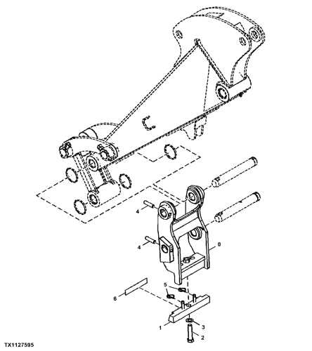
When evaluating expenses related to machinery components, it’s essential to analyze various factors that influence pricing. These elements can range from the type of component needed to the supplier chosen for procurement. Understanding these variables helps in making informed financial decisions.
Factors Influencing Costs
Several aspects play a role in determining the overall expenditure on machinery components. Brand reputation, material quality, and availability can significantly impact prices. Additionally, aftermarket alternatives may offer cost savings but could compromise durability.
Budgeting for Replacement

Setting aside a budget for component replacements is vital for maintaining operational efficiency. Regular maintenance can prevent unexpected failures, leading to more predictable expenses. Here’s a breakdown of potential costs:
| Component Type | Estimated Cost |
|---|---|
| Hydraulic Components | $200 – $1,500 |
| Engine Parts | $100 – $2,000 |
| Transmission Components | $300 – $1,800 |
Online Resources for Diagram Access
In today’s digital age, finding technical illustrations and schematics has become increasingly accessible. Various platforms offer valuable insights and resources for enthusiasts and professionals alike, making it easier to understand machinery components and their relationships.
Specialized Websites
Numerous dedicated websites cater to those seeking detailed visuals. These platforms often provide comprehensive catalogs of equipment illustrations, ensuring users can quickly find the information they need. Membership options may grant additional access to exclusive materials, enhancing the user experience.
Community Forums
Online communities serve as excellent hubs for sharing resources. Participants frequently exchange links and upload their own findings, allowing members to delve into a vast array of technical content. Engaging in discussions can lead to discovering the ultimate resources for specific needs, often recommended by experienced users.