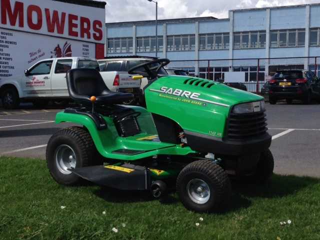
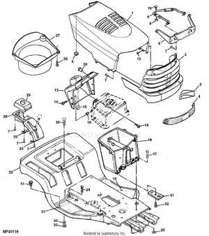
John Deere Sabre 1742 Parts Breakdown
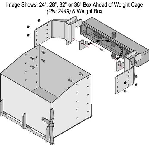
Understanding how different elements of machinery work together is crucial for efficient maintenance and repair. Each component plays a specific role, contributing to the overall functionality of the equipment. Knowing the layout of these elements can simplify both routine inspections and unexpected repairs, saving valuable time and resources.
To keep a machine in top condition, it’s important to familiarize yourself with the structure of its individual parts. Whether for regular servicing or emergency troubleshooting, this knowledge enables more informed decisions and enhances operational efficiency. In the following sections, we’ll explore essential aspects of the machine’s framework and how each element supports optimal performance.
By focusing on key aspects of component placement and connectivity, you’ll gain a clearer understanding of the machine’s internal mechanics. This deeper insight allows for more precise interventions and ensures the longevity of the equipment. Regular checks and appropriate adjustments can prevent potential breakdowns, ensuring the smooth operation of your machinery.
Key Components and Their Functions
The essential systems of this model include various mechanical and electrical elements that work together to ensure smooth operation. Each component plays a vital role in maintaining performance and reliability, contributing to the machine’s overall durability and efficiency in demanding tasks.
Mechanical Elements
The core of the machine’s framework includes the transmission, which ensures proper power distribution, and the cutting mechanism responsible for clean and precise operation. Additionally, the drive system provides the necessary movement, ensuring efficient use on different terrains.
Electrical Components
The electrical systems manage the engine’s ignition and operational controls. These circuits help maintain the engine’s performance and ensure reliable starts and stops. Battery and wiring systems connect all the necessary parts to power the machine and its controls effectively.
Engine Components Breakdown
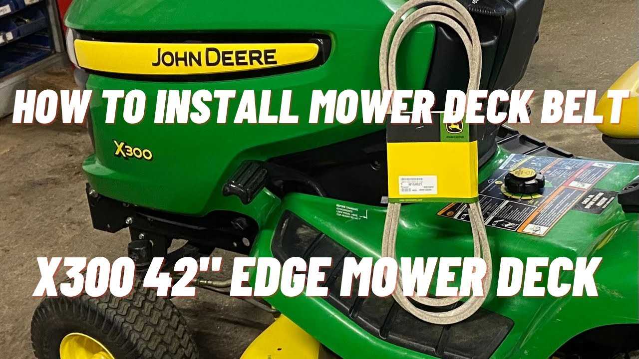
The internal structure of an engine consists of several key elements that work together to ensure efficient operation. Understanding how these elements interact can help in both maintenance and troubleshooting, ensuring smooth performance and longevity. Each section plays a critical role in converting fuel into the energy required for the machine to function.
Main Functional Elements
At the heart of the system are the pistons, crankshaft, and cylinders. These components collaborate to generate mechanical power. The cylinder block, often regarded as the engine’s backbone, houses the pistons, which move up and down, creating the force necessary to drive the crankshaft. This motion converts the energy from combustion into rotational power.
Supporting Systems
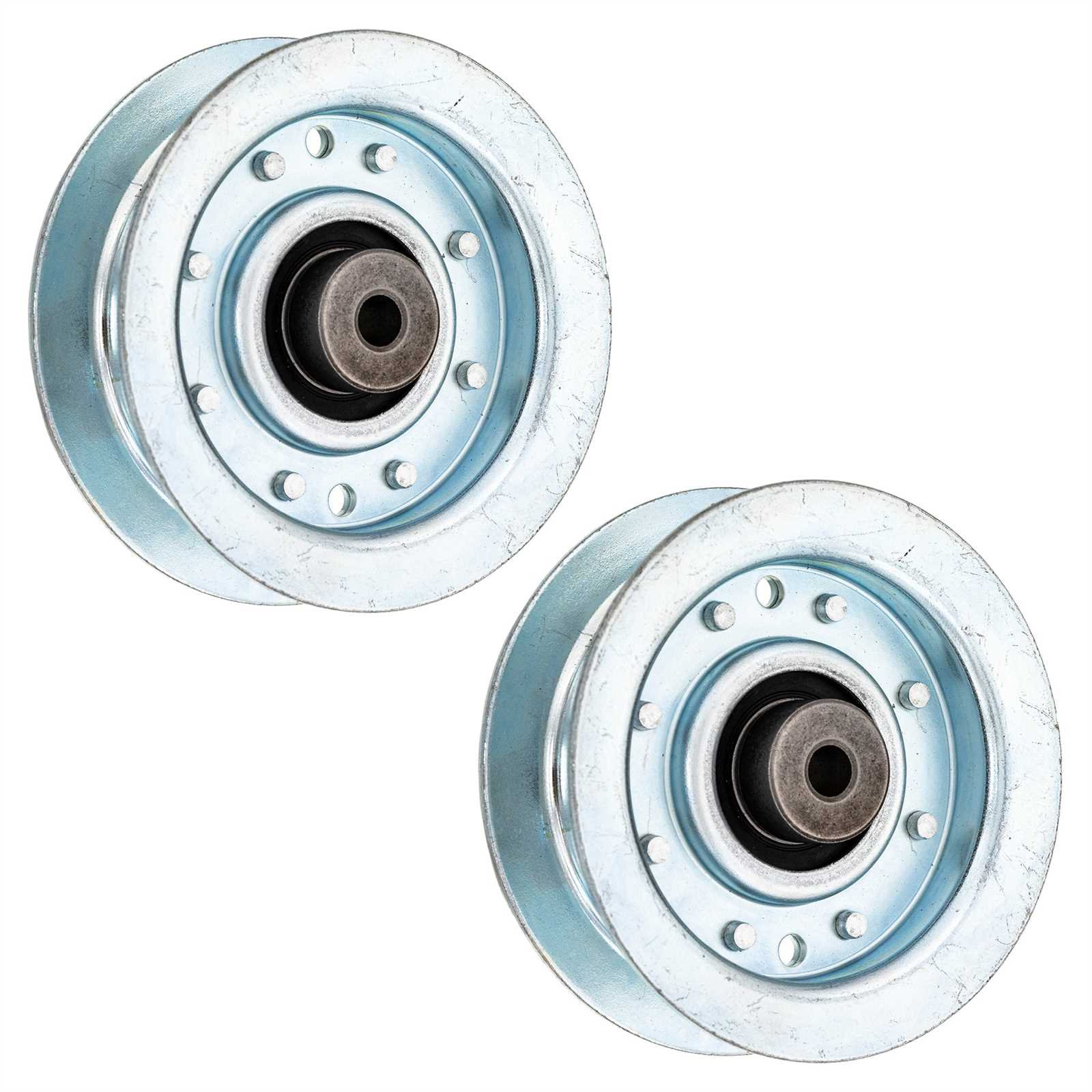
Alongside the core components are critical supporting systems like the cooling and lubrication mechanisms. These ensure the engine operates at optimal temperature and reduces friction between moving parts. The cooling system prevents overheating, while proper lubrication minimizes wear, promoting durability and sustained performance.
Transmission System Layout
The transmission system is a crucial part of any riding equipment, responsible for transferring power from the engine to the wheels. Understanding its configuration helps in both maintenance and efficient operation. The layout consists of several interconnected components that work together to ensure smooth performance and control.
- Clutch Mechanism: Allows for the seamless engagement and disengagement of power flow between the engine and the drivetrain.
- Gearbox: Contains various gears that adjust the output speed and torque to match the driving conditions.
- Drive Belt: Transfers the mechanical force from the engine to the rear axle, playing a pivotal role in motion.
- Axle Assembly: Connects the transmission to the wheels, ensuring even distribution of power and stability during operation.
- Control Levers: Provide the operator with the ability to shift gears and control speed with precision.
Each part of the transmission system plays a specific role, and understanding these elements is essential for proper upkeep and troubleshooting. A well-maintained system ensures efficient power transfer and enhances the overall performance of the vehicle.
Steering Mechanism and Controls
The steering system plays a crucial role in ensuring precise maneuvering and control of the vehicle. Its components work together to translate the operator’s movements into responsive adjustments, allowing for smooth directional changes. Proper maintenance of this system ensures effective control and minimizes the risk of mechanical failure.
Steering Wheel serves as the primary interface between the operator and the vehicle’s direction. By turning the wheel, the driver can effectively command the vehicle to move in the desired direction. This mechanism is linked to other critical components that ensure accurate response to every input.
The linkage system is a series of mechanical connections that transmit the rotational movement of the wheel into the actual movement of the tires. These interconnected parts are designed to endure stress while providing fluid motion, ensuring that each turn is smooth and consistent.
Regular inspection and adjustment of the controls are essential for maintaining optimal performance. Ensuring that all components remain aligned and lubricated can prevent steering issues and enhance the
Deck and Blade Assembly Guide
The proper setup of the cutting platform and its components is essential for achieving an even and efficient mowing performance. Understanding the arrangement and positioning of each part ensures that the machine operates smoothly, delivering optimal results in various conditions. Below, you will find a step-by-step guide to assembling these key elements.
- Start by securely attaching the cutting deck to the main structure, ensuring all mounting points are aligned correctly.
- Install the blades by positioning them onto the spindle shafts, making sure they are oriented properly for even rotation.
- Check that the pulleys and belts are properly tensioned to ensure smooth blade operation without unnecessary friction.
- Adjust the height settings for the cutting platform, calibrating it according to the desired grass length and terrain type.
- Inspect all connections and fasteners, tightening any loose bolts or components that may affect performance.
Following these steps guarantees that the mowing system works efficiently, providing a clean cut with minimal effort. Regular maintenance and inspection of the assembly will further extend its durability
Electrical System Wiring
The electrical framework in machinery is essential for proper functionality, ensuring that all components operate harmoniously. This section provides an overview of the wiring intricacies involved in the system, highlighting the critical connections that facilitate the seamless flow of electricity throughout the unit.
A thorough understanding of the wiring layout is vital for effective troubleshooting and maintenance. Each connection point plays a significant role in the system’s performance, and knowing how to navigate these can enhance the efficiency of repairs. Proper insulation and secure fittings are also key factors in preventing electrical faults.
By familiarizing oneself with the wiring structure, users can ensure optimal performance and longevity of the equipment. Regular inspections and adherence to safety standards are imperative to maintain a well-functioning electrical system.
Fuel System Parts
The fuel system is a crucial component of any machinery, ensuring that the engine receives the necessary fuel for optimal performance. Understanding the various elements of this system can aid in proper maintenance and troubleshooting, enhancing the overall efficiency of the equipment.
Key components of the fuel system include:
- Fuel Tank: The reservoir that stores fuel until it is needed by the engine.
- Fuel Pump: A device that moves fuel from the tank to the engine, ensuring a steady supply under pressure.
- Fuel Filter: This component cleans the fuel before it reaches the engine, preventing contaminants from causing damage.
- Fuel Lines: These hoses transport fuel from the tank to the engine, playing a vital role in the fuel delivery process.
- Injector: A crucial element that atomizes fuel for efficient combustion within the engine.
Regular inspection and replacement of these components can lead to improved engine performance and longevity. Always refer to the equipment manual for specific recommendations on maintenance practices.
Braking Mechanism Structure
The braking mechanism is a vital component in ensuring the safety and control of any vehicle. It is designed to reduce the speed of movement or bring it to a complete stop. Understanding the structure and functionality of this system is crucial for effective maintenance and operation.
Key Components
- Brake Pedal: The interface through which the operator applies force to engage the braking system.
- Master Cylinder: Converts the force from the pedal into hydraulic pressure.
- Brake Lines: Transmit hydraulic fluid from the master cylinder to the brake assemblies.
- Brake Calipers: House the brake pads and press them against the rotor to create friction.
- Brake Pads: The friction material that grips the rotor, slowing down the wheel.
- Rotors: Disc components that provide a surface for the brake pads to act upon.
Operation Process
- The operator presses the brake pedal, initiating the process.
- The master cylinder generates hydraulic pressure, which travels through the brake lines.
- The calipers engage, pushing the pads against the rotors.
- The friction created between the pads and rotors slows the vehicle.
- Once the desired speed is reached, the operator releases the pedal, disengaging the mechanism.
Regular inspection and maintenance of each component are essential for the efficient operation of the braking system. Identifying wear and tear can prevent potential failures and enhance overall safety.
Drive Belt Configuration
The configuration of the drive belt is essential for the optimal performance of lawn maintenance equipment. Proper alignment and tension of the belt contribute significantly to the overall efficiency of the machine. Understanding the setup can help in troubleshooting issues related to power transmission and enhance the longevity of components.
To ensure a correct installation, refer to the following table which outlines the necessary steps for configuring the drive belt:
| Step | Description |
|---|---|
| 1 | Disconnect the power source to avoid accidental starts during maintenance. |
| 2 | Remove the protective cover to access the drive components. |
| 3 | Inspect the existing belt for wear and damage; replace if necessary. |
| 4 | Position the new belt according to the specified routing instructions. |
| 5 | Adjust the tension by utilizing the appropriate adjustment mechanism. |
| 6 | Reattach the protective cover and reconnect the power source. |
Following these steps will help maintain the drive system’s effectiveness, preventing potential mechanical failures and ensuring a smooth operation.
Seat and Control Levers
The comfort and usability of a riding mower significantly depend on the seating arrangement and the design of control mechanisms. A well-structured seating area provides adequate support and ensures the operator can manage the machine effectively, enhancing the overall mowing experience. This section focuses on the essential components related to the seating and the control levers that enable efficient operation.
Ergonomic Design
The seat’s ergonomic design is crucial for extended periods of use. It should offer sufficient cushioning and support, allowing the operator to maintain a proper posture while maneuvering the mower. Adjustable features can accommodate different user preferences, ensuring maximum comfort and reducing fatigue during operation.
Control Functionality
Control levers play a vital role in the mower’s functionality. They should be intuitively positioned for easy access, allowing the operator to make swift adjustments while driving. The responsiveness of these levers is essential for precise control, facilitating smooth operation and enhancing overall efficiency. A well-designed control system contributes to a more enjoyable mowing experience.
Front and Rear Wheels Assembly
The assembly of the front and rear wheels is crucial for maintaining the stability and functionality of any outdoor equipment. Proper alignment and secure attachment of the wheels ensure optimal performance and safety during operation. This section outlines the essential components and considerations involved in assembling these critical parts.
Components Overview
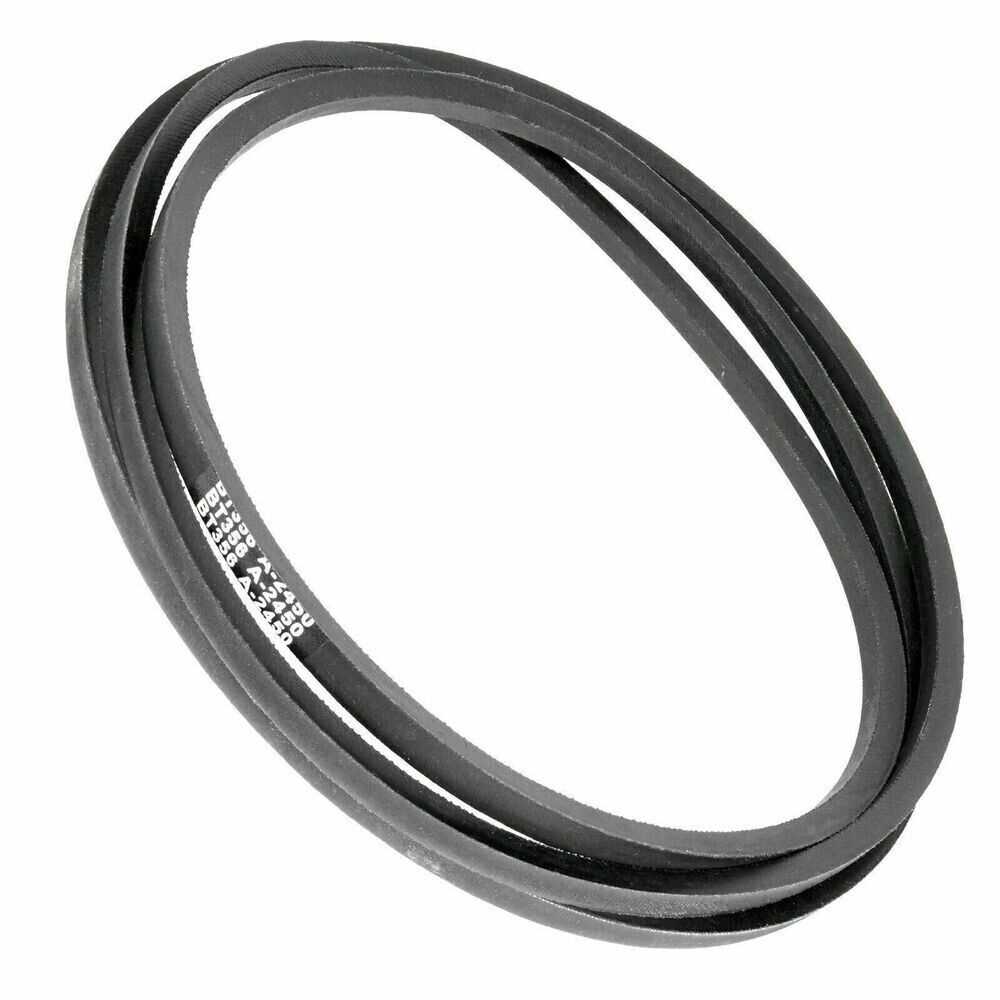
Understanding the various elements involved in wheel assembly is vital for effective maintenance. The primary components typically include the wheel rims, tires, axle shafts, bearings, and hub assemblies. Each part plays a significant role in ensuring smooth movement and support.
Assembly Process
Follow these steps for an effective wheel assembly:
| Step | Description |
|---|---|
| 1 | Inspect all components for wear or damage before beginning the assembly. |
| 2 | Attach the tire to the wheel rim, ensuring it is seated evenly around the circumference. |
| 3 | Insert the axle shaft through the wheel hub, aligning it properly. |
| 4 | Secure the wheel assembly onto the main frame using the provided bolts and washers. |
| 5 | Perform a final inspection to ensure everything is tightened and aligned correctly. |
Maintenance and Replacement Tips
Proper upkeep and timely exchanges of components are essential for the longevity and efficiency of any machine. Regularly inspecting and servicing vital elements can prevent unexpected breakdowns and ensure smooth operation. This section provides valuable insights into best practices for maintaining and replacing critical parts of your equipment.
Regular Inspection
Conducting frequent assessments of your machinery allows you to identify wear and tear before it escalates into a significant issue. Focus on the following areas during your inspections:
| Component | Recommended Frequency of Inspection |
|---|---|
| Blades | Every 10 hours of operation |
| Belts | Every 20 hours of operation |
| Fluid Levels | Before each use |
| Tires | Every month |
Component Replacement Guidelines
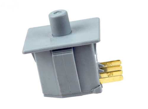
When it comes to swapping out old or damaged parts, adhere to the following recommendations:
- Always consult the manufacturer’s specifications for compatible replacements.
- Keep a log of replacement dates to track the lifespan of components.
- Use high-quality parts to ensure optimal performance.