Understanding the John Deere XT140 Parts Layout
Understanding the internal structure and the interconnected elements of specialized machinery is key to ensuring its smooth operation and longevity. Each piece of equipment consists of numerous elements working together, and knowing how they fit and function can help you maintain, repair, or upgrade your machine efficiently.
In this section, we’ll explore the detailed layout and interrelation of various mechanical and electrical systems that form the backbone of robust equipment. Whether you’re looking to enhance your understanding of its assembly or seeking to identify a specific component, this overview will provide a clear and detailed guide to the essential parts and their functions.
By examining the structural and functional elements, you’ll gain insights into how to address issues more effectively, whether it’s for routine upkeep or troubleshooting. This guide will serve as a vital resource for anyone looking to maximize performance and extend the lifespan of their equipment.
Understanding the Structure of the XT140 Model
The design of this machine is a well-thought-out combination of functionality and durability, crafted to ensure maximum efficiency in various tasks. Its layout is organized in such a way that each component plays a critical role in maintaining smooth operation and reliability over extended periods of use. This section will explore the key elements that form the core of the model’s structure, highlighting their arrangement and purpose within the overall framework.
Main Framework and Core Components
At the heart of the model’s architecture lies a sturdy framework that supports all major mechanical elements. The positioning of these parts ensures balanced weight distribution, contributing to the machine’s stability during operation. Key elements include:
- Central drive system for powering essential functions
- Control mechanisms designed for intuitive handling
- Protective casing that shields delicate internal components
Operational Enhancements
Several features are integrated into the structure to enhance overall performance. These improvements help streamline complex tasks while maintaining high levels of precision and control. Important operational enhancements include:
- Advanced transmission system for smoother transitions between tasks
- Hydraulic systems for greater power and flexibility
- Ergonomically designed controls for operator comfort
In summary, the thoughtful assembly of components within this model makes it a reliable choice for users seeking both power and precision in demanding environments.
Main Components of the XT140 System
The system comprises several essential elements that work together to ensure optimal performance and functionality. Each part plays a significant role in maintaining the efficiency and reliability of the equipment, contributing to its overall operation. Understanding these components is key to ensuring proper maintenance and troubleshooting when necessary.
| Component | Description |
|---|---|
| Engine Assembly | The central power source that drives the machinery, designed for high efficiency and durability. |
| Transmission Unit | Responsible for transferring power from the engine to the wheels, ensuring smooth and controlled movement. |
| Hydraulic System | Enables precise control of various functions, including lifting and steering, by utilizing fluid pressure. |
| Electrical Circuitry | Manages the flow of electricity to power various onboard systems, including lighting and sensors. |
| Chassis Frame | Provides structural support for all the components, ensuring stability and safety during operation. |
Detailed Overview of Engine Parts
The internal components responsible for the performance and functionality of the machine’s power unit are essential to ensuring efficient operation. These elements work together in a coordinated system to generate the necessary power and motion, playing a pivotal role in the overall mechanical structure.
Main Elements of the Power Unit
The key sections of the power-generating mechanism include several vital components. These range from the central block responsible for the combustion process to supporting elements that regulate temperature and energy output. Each element is designed to withstand high stress and environmental factors, contributing to the durability and longevity of the engine.
Core Component Interactions
The interaction between the different components is crucial for seamless operation. The main mechanism relies on precision timing and synchronization to convert fuel into mechanical energy. Proper maintenance of these elements is critical to prevent wear and ensure smooth functionality.
| Component | Function |
|---|---|
| Cylinder Block | Houses the combustion chambers and facilitates the power stroke. |
| Piston | Moves within the cylinder to transfer force from expanding gases. |
| Crankshaft | Converts linear motion of the pistons into rotational energy. |
| Cooling System | Regulates engine temperature to prevent overheating. |
| Fuel Injector | Supplies fuel to the combustion chamber at precise intervals. |
Key Features of the Transmission Assembly
The transmission unit plays a crucial role in ensuring smooth operation by managing the power transfer from the engine to the wheels. It optimizes the energy distribution, enabling efficient movement across different terrains. Understanding its main elements can help in maintenance and troubleshooting.
Main Components
- Gear System: This complex mechanism allows for the adjustment of speed and torque, providing flexibility in performance for various tasks.
- Clutch Mechanism: Responsible for engaging and disengaging power, the clutch ensures a seamless shift between gears while maintaining control over the drive.
- Hydraulic Control: This feature regulates the movement of fluid within the system, contributing to smoother transitions and reduced wear on internal components.
Performance Benefits
- Improved fuel efficiency through optimized power distribution.
- Enhanced durability due to reduced friction in the gear assembly.
- Better adaptability for varying load conditions and environments.
Hydraulic System Layout and Functionality
The hydraulic system plays a crucial role in ensuring efficient power transmission throughout various mechanisms. By converting mechanical energy into fluid pressure, this network of components drives different operations, offering controlled motion and force distribution. Understanding the arrangement of this system is key to maintaining optimal performance in any machinery, as it impacts both productivity and operational stability.
Core Components and Their Roles
The layout consists of several fundamental elements, including pumps, valves, actuators, and reservoirs. These components work together to generate, regulate, and distribute fluid under pressure. The pump delivers the necessary force, while valves control the direction and flow rate. Actuators, like cylinders or motors, then convert fluid pressure into mechanical action, enabling precise movements.
Flow Control and Pressure Regulation
Effective pressure management is critical for ensuring smooth operation. Various control devices are used to monitor and adjust flow rates, safeguarding the system from overload or inefficiencies. Proper regulation also helps prevent unnecessary wear and tear on components, extending the lifespan of the machinery and ensuring consistent functionality under varying loads.
Electrical Circuitry in the XT140 Model
The intricate electrical framework of this particular model plays a crucial role in its overall functionality. Understanding how the various components interact is essential for effective maintenance and troubleshooting. This section delves into the key elements of the circuitry, providing insights into their connections and operations.
Key Components of the Electrical System
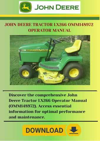
The electrical system comprises several vital elements, including the battery, ignition system, and various sensors. Each component is designed to ensure optimal performance and reliability. The battery serves as the primary power source, supplying energy to start the engine and run auxiliary systems. The ignition system, on the other hand, is responsible for igniting the fuel-air mixture, thus enabling efficient engine operation.
Wiring and Connectivity
Wiring plays a significant role in connecting all components within the electrical framework. Wires must be properly routed and insulated to prevent shorts and ensure safety. Understanding the connectivity of various circuits helps in diagnosing issues and making necessary repairs. By following the wiring layout, technicians can efficiently trace faults and restore functionality.
Exploring the Cooling and Fuel Systems
The efficiency of any machinery heavily relies on its cooling and fuel management mechanisms. Understanding these systems is crucial for maintaining optimal performance and longevity. Effective temperature regulation ensures that components operate within safe limits, while proper fuel delivery maximizes energy output and efficiency.
In this section, we will delve into the key components and functions of both the cooling and fuel systems:
- Cooling System:
- Radiator: Responsible for dissipating heat from the engine.
- Thermostat: Regulates coolant flow based on temperature.
- Water Pump: Circulates coolant throughout the engine and radiator.
- Coolant Hoses: Transport coolant between various components.
- Fuel System:
- Fuel Tank: Stores the fuel supply for the engine.
- Fuel Pump: Delivers fuel from the tank to the engine.
- Fuel Filter: Removes impurities from the fuel before it reaches the engine.
- Injectors: Atomize the fuel for efficient combustion.
Understanding the interplay between these systems is essential for troubleshooting and maintenance. Regular inspection and servicing can prevent common issues such as overheating and fuel starvation, ensuring reliable operation.
Brake and Steering Components Explained
The braking and steering systems are crucial for the safe operation of any vehicle, ensuring control and stability during movement. Understanding the various elements involved in these systems can aid in better maintenance and troubleshooting. This section will explore the key components associated with braking and steering, their functions, and how they contribute to overall vehicle performance.
Braking System Components
- Brake Pads: These are friction materials that press against the rotor to create the stopping force. Regular inspection is essential to ensure optimal performance.
- Rotors: Also known as discs, they are the components against which brake pads press to slow down or stop the vehicle.
- Calipers: These house the brake pads and use hydraulic pressure to clamp them onto the rotors.
- Brake Lines: These are responsible for transmitting hydraulic fluid from the master cylinder to the calipers, facilitating the braking action.
- Master Cylinder: This component generates the hydraulic pressure necessary for braking by pushing fluid through the lines.
Steering System Components
- Steering Wheel: The primary interface for the operator to control the direction of the vehicle.
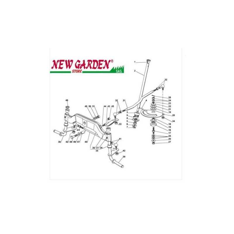
- Steering Column: This connects the steering wheel to the steering mechanism, allowing for the transfer of movement.
- Rack and Pinion: This mechanism converts the rotational motion of the steering wheel into the linear motion required for turning the wheels.
- Power Steering Pump: This assists in steering effort by providing hydraulic pressure, making it easier to turn the wheel.
- Linkage Components: These connect the steering mechanism to the wheels, enabling precise control and responsiveness.
Understanding the Role of the Drivetrain
The drivetrain is a critical system that facilitates the transfer of power from the engine to the wheels, enabling movement and maneuverability. This essential assembly consists of various components that work together to ensure efficiency and performance. By comprehending its function, operators can maintain their machinery effectively and enhance its overall functionality.
Key elements of the drivetrain include the transmission, driveshafts, and differential, each serving a unique purpose in the power delivery process. The transmission adjusts the torque and speed generated by the engine, while driveshafts transmit this power to the axles. The differential allows for variations in wheel speed during turns, contributing to stability and control.
| Component | Function |
|---|---|
| Transmission | Modifies engine power for speed and torque adjustments |
| Driveshaft | Transmits rotational power from the transmission to the wheels |
| Differential | Distributes power to wheels, allowing for different speeds during turns |
Suspension System Parts Overview
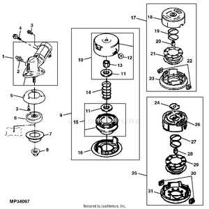
The suspension framework of a vehicle plays a crucial role in ensuring a smooth and stable ride. It comprises various components that work together to absorb shocks, maintain wheel alignment, and provide comfort to the operator. Understanding the elements involved in this system can help in diagnosing issues and performing necessary maintenance.
Key Components
Among the essential elements of the suspension framework are the springs, dampers, and control arms. Springs serve to absorb impacts from uneven terrain, while dampers control the oscillations of the springs, providing stability during movement. Control arms connect the suspension to the vehicle’s chassis, allowing for controlled wheel movement and alignment.
Maintenance and Upgrades
Regular inspections and timely replacements of suspension components are vital for optimal performance. Upgrading certain elements, such as replacing standard springs with high-performance variants, can enhance handling and ride quality. Ensuring that the entire suspension assembly is in good condition contributes to overall safety and functionality.
Exploring the Cutting Mechanism Parts
The cutting system of any mowing apparatus plays a crucial role in its efficiency and performance. Understanding the individual components that contribute to this mechanism is essential for maintenance and optimal functionality. Each element has a specific purpose that collectively enhances the cutting process.
Here are the primary components involved in the cutting mechanism:
- Blades: The primary tools responsible for cutting grass and foliage, designed for precision and durability.
- Spindle Assembly: This component supports and rotates the blades, allowing them to operate effectively.
- Deck: The casing that houses the cutting blades, protecting them while providing structural support.
- Belt: This part transmits power from the engine to the spindle, ensuring the blades spin at the correct speed.
- Height Adjustment Mechanism: Enables the operator to modify the cutting height, adapting to different grass types and conditions.
Each of these elements must be regularly inspected and maintained to ensure optimal performance. Neglecting any part can lead to diminished cutting efficiency and potential damage to the overall system.
Protective Covers and Safety Mechanisms
Ensuring the security of machinery and its operators is paramount in any operational environment. Various shielding elements and safety features play a critical role in minimizing risks and safeguarding essential components from environmental factors and accidental damage. This section highlights the significance of these protective elements in enhancing durability and user safety.
Protective covers are designed to encase vulnerable parts of equipment, providing a barrier against debris, moisture, and other external hazards. These components are typically made from robust materials that can withstand harsh conditions. In addition, safety mechanisms, such as automatic shut-off systems and emergency stops, are crucial in preventing accidents and injuries, ensuring that users can operate machinery with confidence.
| Type | Function | Material |
|---|---|---|
| Protective Cover | Prevents debris and moisture ingress | High-density plastic or metal |
| Safety Guard | Shields moving parts to prevent contact | Steel or reinforced polymer |
| Emergency Stop Button | Instantly halts operation in emergencies | Durable plastic with rubber cover |
| Shut-off Mechanism | Automatically stops machinery when not in use | Electrical components and sensors |
By incorporating these protective and safety features, manufacturers can enhance the longevity of their products while ensuring a secure working environment for operators. Regular maintenance and inspection of these elements are also vital for optimal performance and reliability.
Best Practices for Maintaining XT140 Parts
Proper upkeep of machinery components is essential for optimal performance and longevity. Adopting effective maintenance strategies can prevent premature wear and ensure reliable operation. This section outlines key practices that every owner should consider to keep their equipment in peak condition.
Regular Inspections
Conducting frequent checks of critical elements is vital to identify potential issues before they escalate. This involves examining connections, seals, and surfaces for signs of damage or wear. Addressing minor problems early can save significant time and resources later.
Cleaning and Lubrication
Keeping components clean is essential for preventing the accumulation of dirt and debris, which can lead to operational failures. Additionally, applying appropriate lubricants to moving parts reduces friction and enhances efficiency. Following the manufacturer’s recommendations for cleaning agents and lubricants ensures compatibility and effectiveness.
| Maintenance Task | Frequency | Notes |
|---|---|---|
| Visual Inspection | Weekly | Look for leaks and unusual wear |
| Cleaning | Monthly | Use non-abrasive cleaners |
| Lubrication | Monthly | Follow manufacturer guidelines |
| Comprehensive Check | Seasonally | Inspect all components thoroughly |