Understanding the Components of the Quantum Q6 Edge
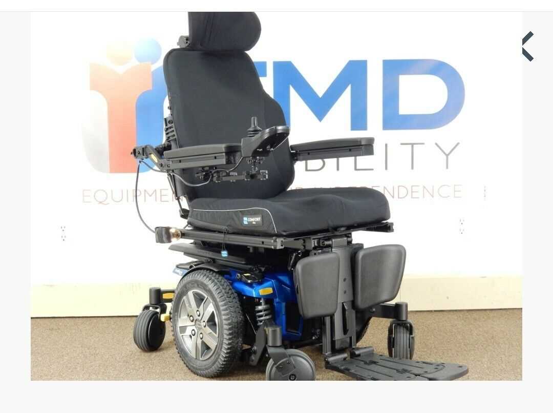
Understanding the configuration of mobility systems is essential for ensuring their functionality and longevity. These specialized devices are designed with intricate systems that work together to deliver a seamless user experience. Knowing the various elements that make up these systems allows users and technicians alike to maintain and repair them efficiently.
Each component plays a significant role in the overall operation, from the driving mechanism to the supportive structures. This guide offers a comprehensive breakdown of these elements, shedding light on their interaction and importance. Whether you are troubleshooting or simply learning about the engineering behind these advanced mobility aids, this information is key to mastering the details of their construction.
The following sections will provide a detailed analysis of the internal and external structures, offering clarity on how each piece contributes to the reliability and performance of the entire system. By the end, you will have a clearer understanding of the integral components that power these modern solutions.
Key Components of the Quantum Q6 Edge
The model is designed with a set of advanced elements that ensure smooth performance and reliability. Each element serves a specific role in providing a comfortable, efficient, and highly responsive experience for the user. Understanding these elements helps in maintaining and troubleshooting the system as a whole.
Drive Mechanism
The core of the movement system relies on a highly efficient drive unit. This mechanism is responsible for delivering power to the wheels, allowing for seamless navigation across various surfaces. With a combination of precision engineering and durable materials, the drive system ensures consistent and powerful motion.
Control Interface
The command system is another essential aspect, giving the user full control over the mobility features. It consists of an intuitive interface designed for easy operation, allowing for adjustments in speed, direction, and other functional settings. This system is carefully calibrated to respond quickly and accurately to user inputs.
Understanding the Electrical System Layout
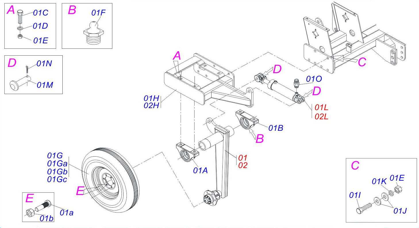
The electrical system in a modern mobility device is a complex network that enables smooth operation and control. It consists of several components working together to manage power distribution, control signals, and ensure proper functionality. Understanding how these elements interact is crucial for troubleshooting and maintenance.
Power delivery is a key aspect, involving connections that link the battery to various motors and controllers. These circuits are designed to efficiently handle the demands of the device, distributing energy to where it’s needed most.
Equally important is the control system, which includes wiring configurations responsible for interpreting user inputs and converting them into precise movements. This intricate setup ensures that every command, from steering to speed adjustments, is executed accurately.
Motor and Drive Assembly Overview
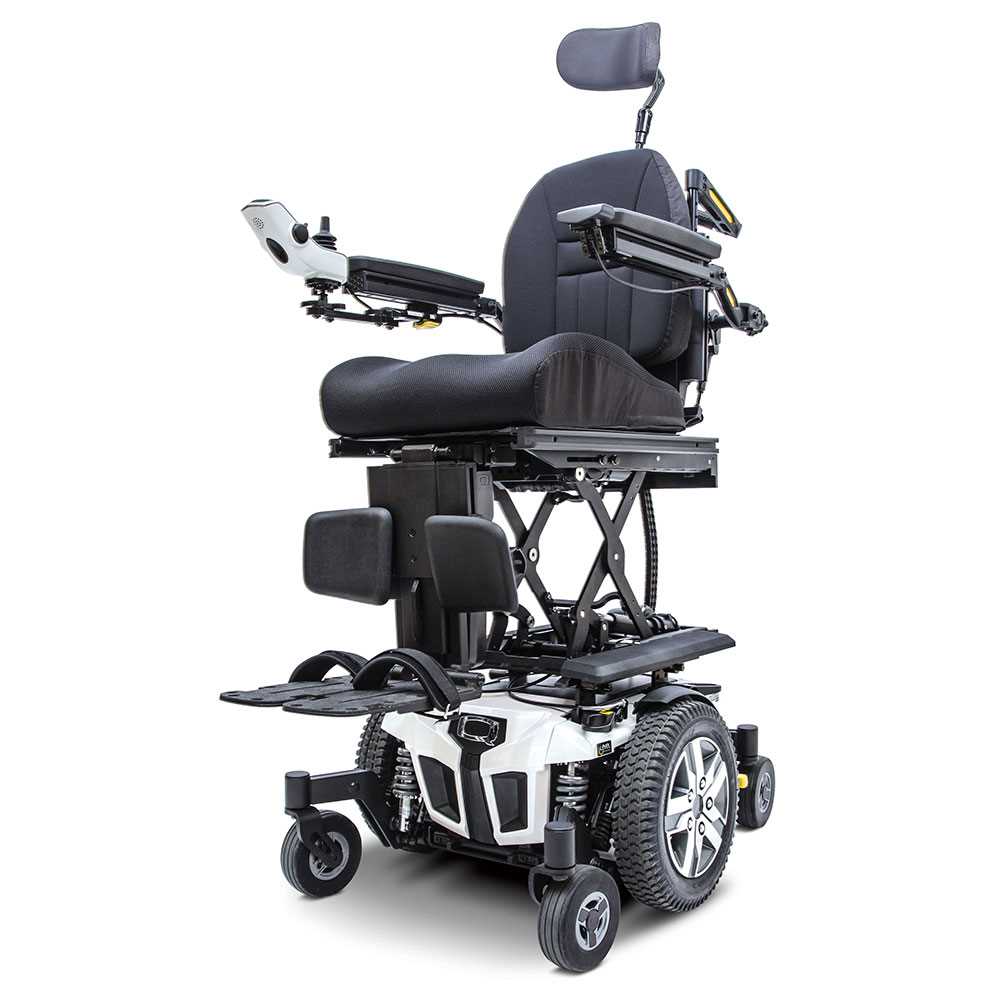
The motor and drive system plays a crucial role in the overall functionality, ensuring smooth and reliable movement. Understanding its components and how they work together is essential for maintaining optimal performance. This section will explore the key elements involved in this system, offering insights into their functions and interaction.
Main Components

- Drive Unit: The core component that translates electrical power into motion, enabling controlled movement across different terrains.
- Motor: Responsible for generating the necessary power output to move the unit forward or backward, while also supporting efficient handling.
- Gearbox: A vital part of the system, the gearbox adjusts torque and speed to suit specific requirements, ensuring consistent performance.
Operational Mechanics
- The motor receives input from the control system, which determines speed and direction.
- The drive unit transmits this energy to the wheels, ensuring fluid movement.
- The gearbox optimizes the power flow, balancing force and velocity as needed during operation.
Each of these components works in harmony, creating a seamless driving experience and ensuring the system can handle various conditions effectively.
Battery Placement and Wiring Configuration
The proper alignment and connection of power sources are essential for ensuring optimal performance and longevity. The power units need to be carefully installed in designated areas, taking into account both their orientation and accessibility for maintenance. Incorrect positioning or wiring could lead to operational inefficiencies or even damage to the system.
Correct alignment is critical for maintaining balance and ensuring uninterrupted power delivery. The placement of the units should be such that they remain secure during movement, with sufficient ventilation to prevent overheating. Pay attention to the wiring, as each connection must be firmly attached to avoid potential disruptions in power flow.
Proper cable management is also crucial. Ensure that the wiring follows the recommended path, avoiding tight bends or excessive stretching. Clear labeling of the connections will aid in future troubleshooting or maintenance. Adherence to these guidelines will ensure a reliable and efficient power system.
Control Module and Joystick Connections
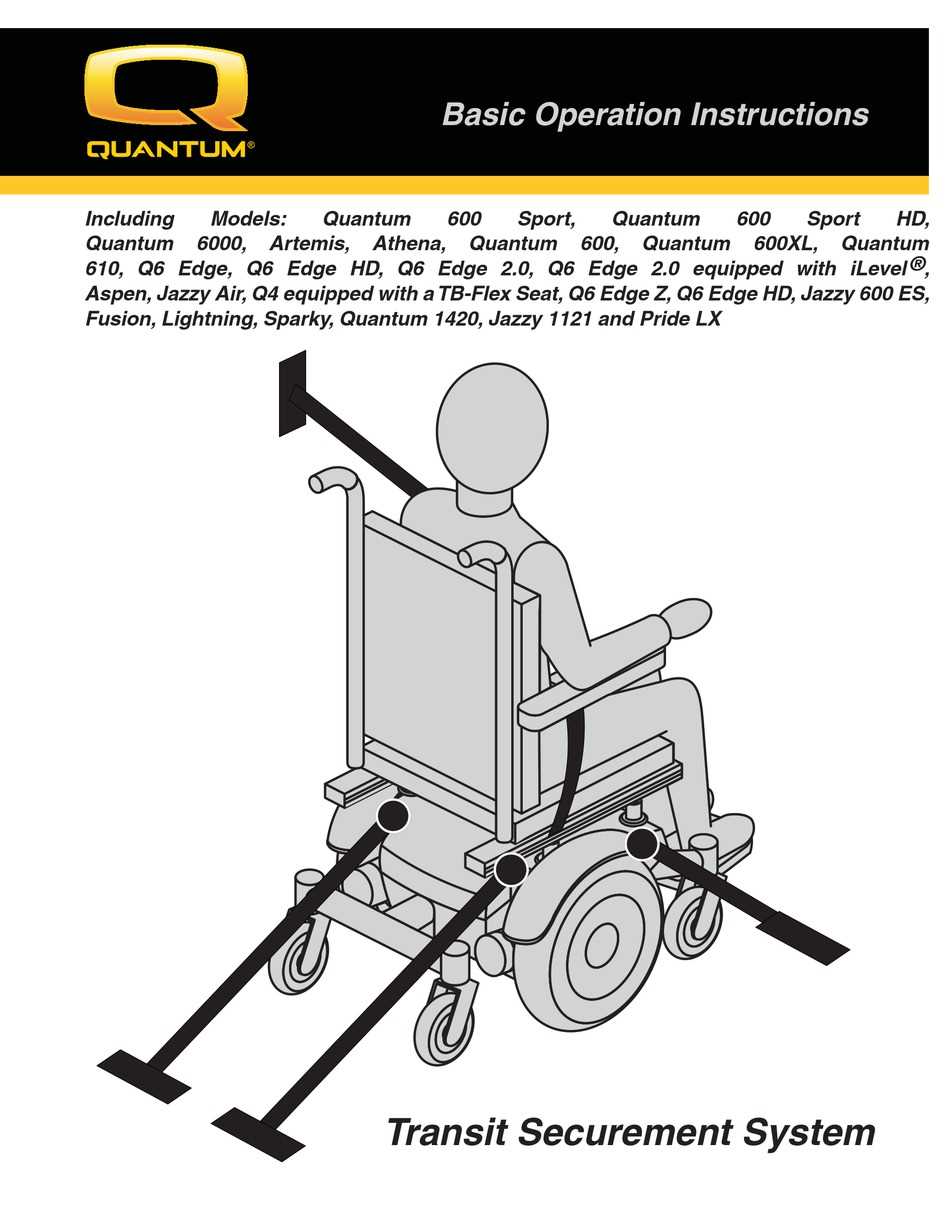
The interaction between the control system and the maneuvering unit is essential for ensuring smooth and responsive handling. The connection points allow seamless communication between the central unit and the driving controls, which enhances user precision and overall reliability during operation. Understanding these connections ensures optimal performance and minimal disruptions during use.
Main Connection Interface
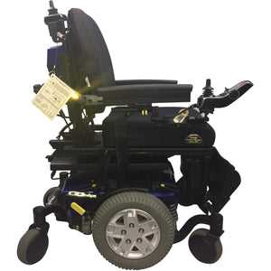
The central hub serves as the primary location where the various control inputs are processed. It links the input commands to the core system, allowing for real-time adjustments and movement. Ensuring that these connections are secure and properly aligned is critical for maintaining control accuracy.
Communication Pathways
The communication lines between the main control and the maneuvering device must remain uninterrupted to prevent any delay or malfunction in response. These pathways are carefully engineered to allow efficient signal transfer, which directly impacts the precision of movement and the user’s overall experience.
Wheel and Suspension Structure Breakdown
The intricate design of the wheel and suspension system plays a pivotal role in the overall performance and stability of a vehicle. This section delves into the essential components that make up this vital structure, emphasizing their functions and interactions to ensure a smooth driving experience.
Understanding the wheel and suspension architecture involves examining several key elements:
- Wheels: The round components that allow the vehicle to roll, providing traction and support.
- Tires: The rubber coverings on the wheels that offer grip and absorb shocks from the road surface.
- Suspension Arms: These link the vehicle’s chassis to the wheels, allowing for controlled movement and stability during driving.
- Shock Absorbers: Devices that dampen the impact of bumps and road irregularities, enhancing comfort and control.
- Coil Springs: Components that support the vehicle’s weight and absorb energy from road impacts, maintaining optimal ride height.
Each of these components interacts with others to form a cohesive system that significantly impacts ride quality and handling. A thorough comprehension of their functions can aid in maintenance and troubleshooting, ensuring longevity and efficiency of the vehicle.
In addition to individual parts, the geometry of the suspension is crucial. Factors such as alignment, camber, and toe settings directly influence how the vehicle handles and responds to driver inputs:
- Alignment: Ensures that all wheels are parallel, promoting even tire wear and stable handling.
- Camber: Refers to the angle of the wheels relative to the road, affecting grip and cornering performance.
- Toe: Involves the direction in which the wheels point, which can impact steering response and stability.
By understanding these aspects of wheel and suspension structure, one can appreciate the complexity and engineering that contribute to vehicle dynamics.
Seat and Cushioning Mechanism Details
The seating and support system of a mobility device plays a crucial role in user comfort and stability. Understanding the intricacies of the cushioning and seat structure can enhance the overall experience, ensuring optimal ergonomic support and pressure distribution during use.
The cushioning element is designed to adapt to the user’s body contours, providing essential support while minimizing pressure points. Materials used in the cushioning are typically selected for their durability and ability to offer varying levels of firmness, catering to different preferences and needs.
In terms of the mechanism, the design incorporates features that allow for adjustments in height and tilt, enabling users to find their ideal seating position. Such adaptability not only enhances comfort but also promotes better posture, which is vital for long-term use. Understanding these components helps in maintaining the equipment effectively and ensures that users benefit from the full range of adjustments available.
Base Frame Construction and Support Points
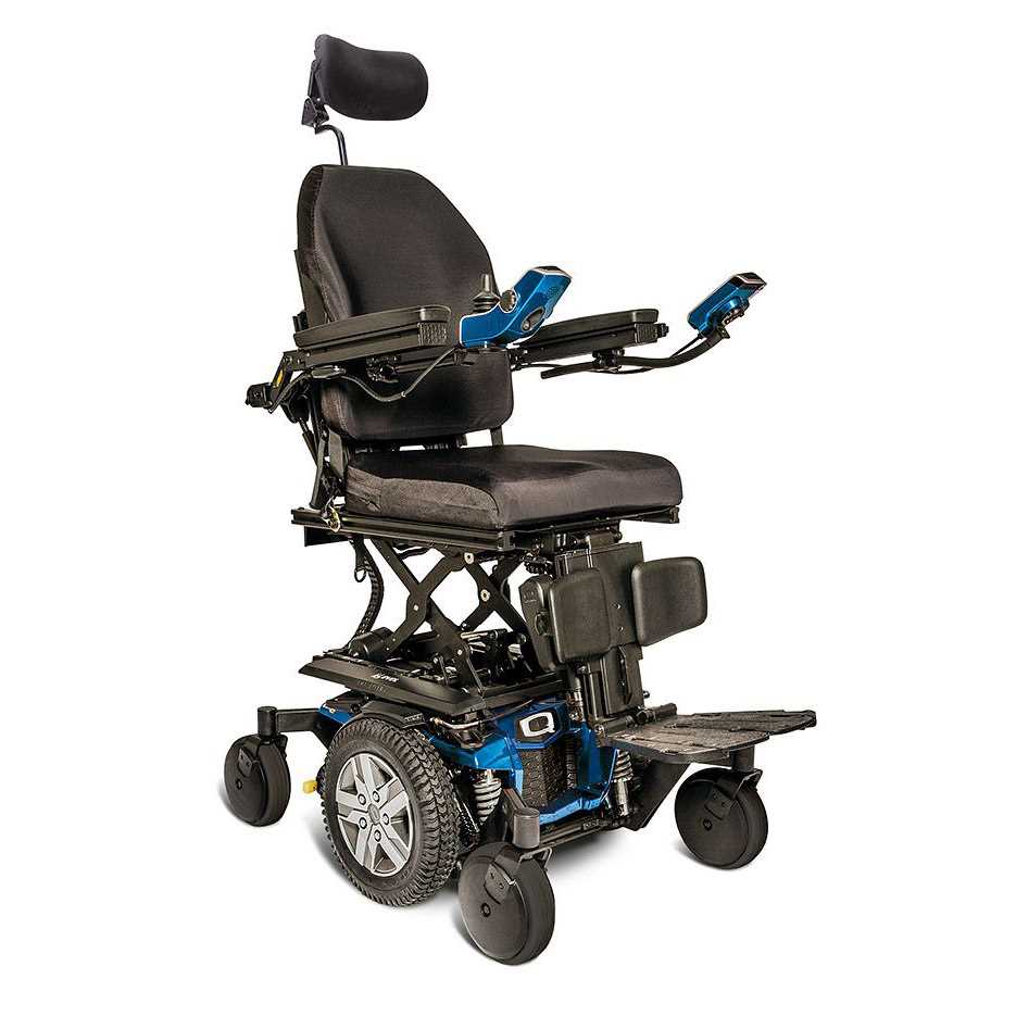
The construction of the foundational structure is crucial for ensuring stability and durability. This component acts as the backbone, providing essential support for the entire assembly. Understanding the design and arrangement of support points is vital for optimizing functionality and performance.
When designing the foundational framework, it is important to consider the materials used and their properties. A robust selection can significantly enhance the overall integrity of the structure. Additionally, strategically placed support points distribute weight effectively, minimizing stress concentrations and preventing deformation over time.
Strengthening the connection between various elements is another critical factor. Proper alignment and secure fastening of components are necessary to maintain structural cohesion. Regular inspection and maintenance of these connections can help identify potential weaknesses before they escalate into serious issues.
In summary, a well-constructed foundational structure with thoughtfully placed support points plays an indispensable role in ensuring the longevity and reliability of the system. Attention to detail in this aspect can lead to enhanced performance and user satisfaction.
Footrest Adjustment and Attachment Guide
This section provides essential information on modifying and securing the footrest for optimal comfort and functionality. Proper adjustment ensures that the user experiences maximum support while enhancing overall stability during use.
To begin, it’s crucial to identify the adjustment mechanism. Most footrests are equipped with a simple lever or knob that allows for height modification. Ensure that the footrest is at the correct height to promote proper posture and prevent strain. When seated, the user’s feet should rest flat against the surface, with the knees at a comfortable angle.
Once the desired height is established, secure the footrest in place by tightening the adjustment mechanism. This step is vital to prevent any movement during operation, which could lead to discomfort or instability.
In addition to height adjustments, it’s important to check the attachment points for the footrest. Inspect all connections to ensure they are firmly secured. Regularly verifying these connections can prolong the life of the equipment and enhance safety during use.
Finally, familiarize yourself with any additional features that may enhance usability, such as pivoting or reclining functions. Understanding these options allows for a more personalized experience, catering to individual preferences and needs.
Brake System Components and Functions
The braking system is a critical component of any vehicle, responsible for ensuring safety and control during operation. It comprises various elements that work together to slow down or stop the vehicle effectively. Understanding these components and their specific roles is essential for both maintenance and optimal performance.
| Component | Function |
|---|---|
| Brake Pedal | Activates the braking system when pressed by the driver. |
| Master Cylinder | Converts the force from the brake pedal into hydraulic pressure. |
| Brake Lines | Transport hydraulic fluid from the master cylinder to the brakes. |
| Brake Calipers | House the brake pads and apply pressure to them against the rotors. |
| Brake Pads | Create friction against the rotors to slow or stop the vehicle. |
| Rotors | Provide a surface for the brake pads to clamp onto, facilitating stopping. |
| Brake Fluid | Transmits force from the master cylinder to the calipers and ensures proper operation. |
Each of these elements plays a vital role in the overall effectiveness of the braking mechanism, contributing to safe driving experiences. Regular inspection and maintenance of these components are crucial for ensuring their proper functioning and longevity.
Accessory Ports and Expansion Options
The ability to enhance functionality through various connectivity options plays a crucial role in modern devices. This section explores the available ports that facilitate additional peripherals and features, allowing users to customize their experience according to specific needs.
Among the common connectivity interfaces, USB ports offer a versatile means to connect a variety of external devices, such as storage solutions, input devices, and other accessories. This flexibility not only increases the usability of the system but also supports seamless integration with a wide range of tools.
Moreover, dedicated expansion slots provide opportunities for hardware upgrades. These slots enable the addition of components like graphic cards or network adapters, significantly boosting performance capabilities and adapting the device to evolving requirements. The potential for expansion ensures that users can keep pace with technological advancements without needing to replace the entire unit.
In addition, audio and video outputs are essential for connecting to external displays and sound systems, enhancing multimedia experiences. These connections allow users to utilize larger screens and superior audio equipment, making them ideal for presentations or entertainment purposes.
Overall, the variety of ports and expansion options available enriches the user experience, empowering individuals to tailor their devices to their unique preferences and requirements.