Understanding the Ford Parts Diagram for Efficient Repairs
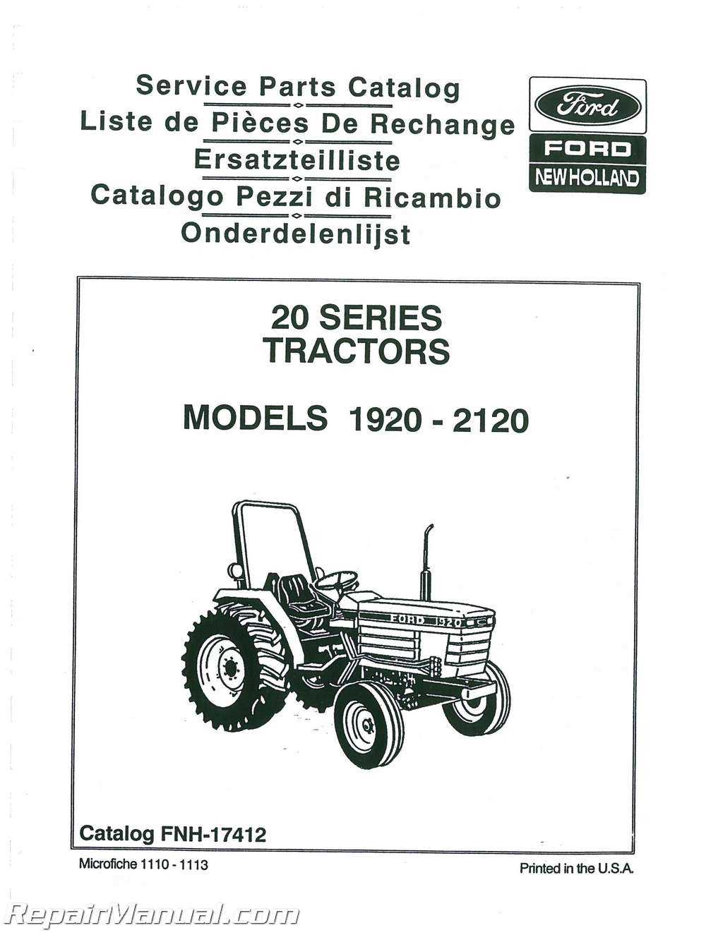
In the realm of automotive engineering, a comprehensive visual representation of vehicle elements serves as a crucial tool for both enthusiasts and professionals. Such illustrations enable a clearer understanding of how various units interact within the system, promoting efficient maintenance and repairs. This knowledge can significantly enhance the longevity and performance of the vehicle.
Whether you are delving into the intricacies of assembly or troubleshooting specific issues, having access to well-structured visual guides is invaluable. These resources not only simplify complex information but also provide insight into the functionality and positioning of critical components. By mastering these layouts, individuals can approach vehicle care with greater confidence and competence.
Moreover, familiarity with these resources fosters a deeper appreciation for the engineering that goes into modern automobiles. It allows for informed discussions and decision-making when it comes to modifications or replacements. Understanding how each element fits into the broader system can lead to more effective and lasting solutions.
Understanding Ford Parts Diagrams
Comprehending the intricate visuals that represent vehicle components is crucial for effective maintenance and repair. These illustrations serve as valuable tools for identifying individual elements and their relationships within the system. By grasping the layout, one can navigate the complexities of automotive repairs more efficiently.
These visuals provide essential insights into how various elements interact, helping both enthusiasts and professionals alike. Knowing the layout allows for quicker identification of issues and streamlined troubleshooting. Ultimately, mastery of these illustrations enhances overall vehicle knowledge and operational effectiveness.
Importance of Accurate Diagrams
Precise representations play a crucial role in ensuring efficiency and effectiveness in various mechanical tasks. They serve as essential references for technicians and enthusiasts alike, facilitating a clear understanding of complex systems.
- Enhance communication among team members.
- Reduce the likelihood of errors during repairs.
- Streamline the process of identifying components.
- Support troubleshooting by providing visual clarity.
Ultimately, reliable representations not only save time but also contribute to the longevity and performance of vehicles. A clear visual guide can make the difference between a successful repair and costly mistakes.
How to Read a Parts Diagram
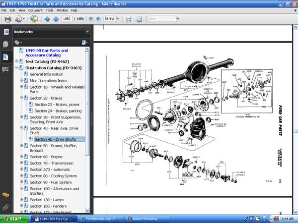
Understanding a visual representation of components is crucial for effective maintenance and repair tasks. Familiarity with symbols and layouts enhances efficiency in identifying elements and their functions.
Key Elements to Recognize
- Symbols: Learn the meaning of each icon used, as they often represent specific parts.
- Lines: Pay attention to the lines connecting elements, indicating relationships and pathways.
- Labels: Refer to annotations that provide vital information about sizes, materials, or specifications.
Steps to Interpret the Visual Guide
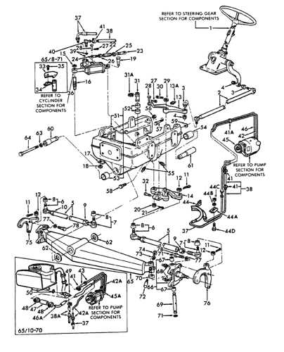
- Start by identifying the main sections of the illustration.
- Focus on the key symbols and their descriptions.
- Trace the connections to understand how components interact.
- Cross-reference with manuals or guides for further clarity.
Common Symbols in Ford Diagrams
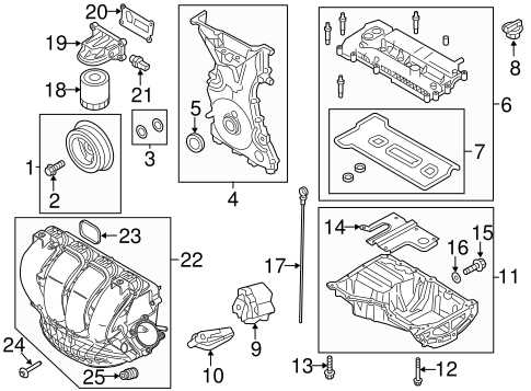
Understanding the visual representations used in automotive schematics is crucial for effective troubleshooting and maintenance. These illustrations utilize a variety of symbols to convey specific information about components and their interconnections. Familiarity with these symbols enables technicians and enthusiasts to interpret the information accurately and carry out repairs with confidence.
Rectangles often signify electrical components, such as relays or fuses, while circles typically represent connection points or terminals. Additionally, triangles can denote various types of sensors or switches, indicating their function within the system.
Lines and arrows play a significant role in illustrating relationships and flow between elements. Solid lines generally indicate a direct connection, whereas dashed lines might represent optional or secondary connections. Understanding these distinctions is essential for diagnosing issues effectively.
Moreover, symbols for various types of fluid, such as oil or coolant, are often depicted in specific colors or with distinct markings. Recognizing these nuances allows for quick identification of potential leaks or malfunctions.
In summary, a solid grasp of the symbols used in these schematics is invaluable. It not only aids in repair and maintenance tasks but also enhances overall knowledge of the vehicle’s systems, leading to more informed decision-making.
Identifying Components Effectively
Understanding the various elements within a mechanical system is crucial for efficient maintenance and repair. This knowledge enables individuals to navigate complex assemblies with confidence, ensuring that every component is recognized and addressed appropriately.
Utilizing visual aids can significantly enhance one’s ability to pinpoint specific items. By employing detailed illustrations and annotated references, users can establish a clearer understanding of each element’s function and location within the overall structure.
Regular training and hands-on experience are essential for mastering the identification process. Engaging in workshops and utilizing interactive resources fosters a deeper connection to the materials, ultimately leading to more informed decision-making during repairs.
Additionally, keeping an organized inventory helps streamline the identification process. A systematic approach allows for quicker access to necessary components, reducing downtime and improving overall efficiency in any mechanical undertaking.
Benefits of Using Diagrams in Repairs
Utilizing visual representations in maintenance tasks significantly enhances the efficiency and accuracy of repairs. These illustrative tools serve as invaluable references, guiding technicians through complex processes and ensuring that every component is handled correctly.
Clarity is one of the ultimate advantages offered by these visuals, simplifying intricate systems and breaking them down into manageable sections. This enables mechanics to quickly identify and resolve issues without unnecessary confusion.
Furthermore, accuracy is improved as these visuals minimize the risk of errors, providing clear indications of where each element fits. This is particularly crucial in preventing misalignments and ensuring optimal functionality of the system post-repair.
Lastly, incorporating these resources into the repair process can enhance training for new technicians, allowing them to grasp concepts faster and develop a deeper understanding of the systems they work on.
Finding OEM Parts with Diagrams
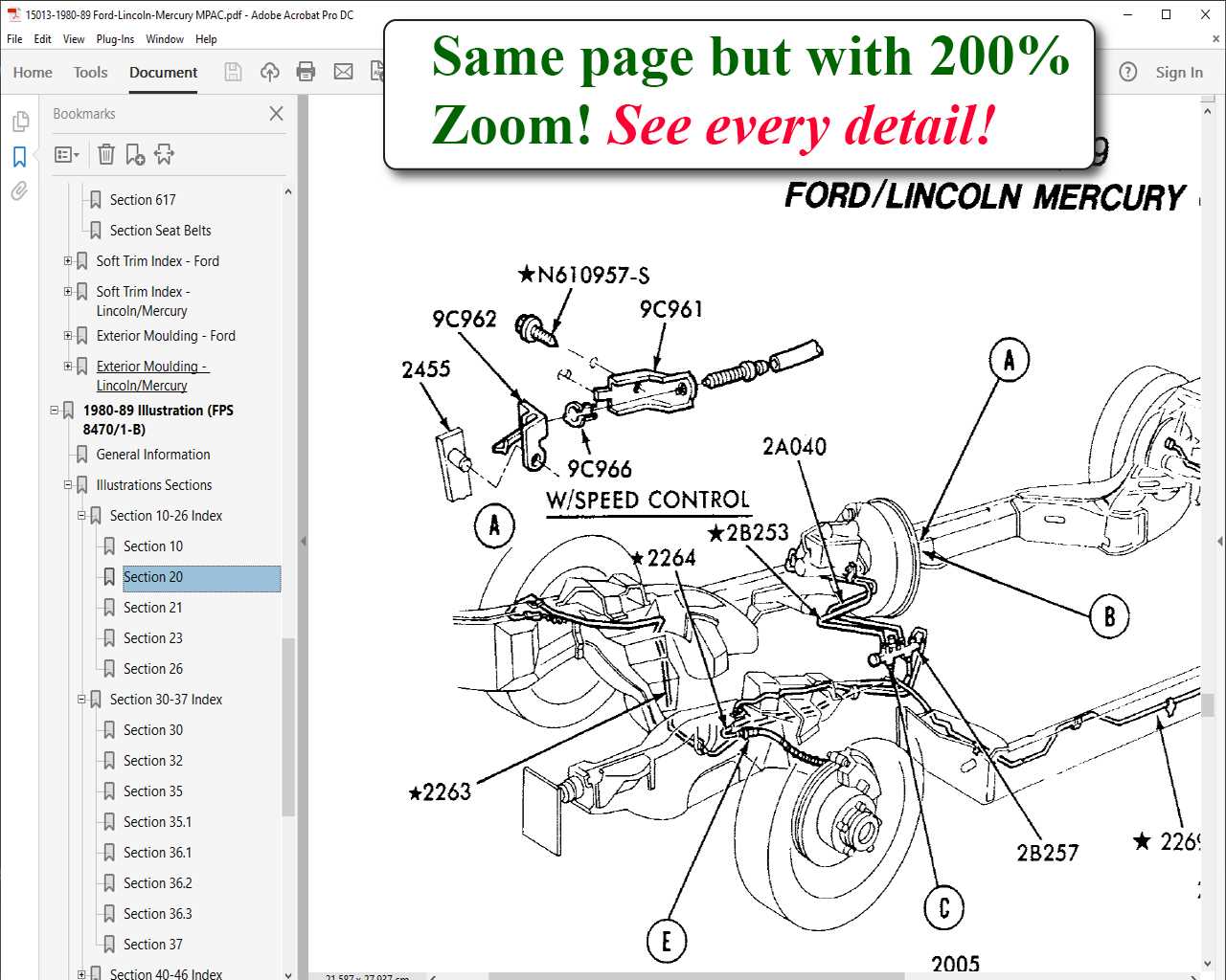
Locating authentic components for your vehicle can be a challenging endeavor, but visual representations simplify this process significantly. By utilizing detailed illustrations, enthusiasts and mechanics can efficiently identify the exact elements needed for repairs or upgrades. Such resources provide clarity and enhance understanding, making it easier to ensure compatibility and quality.
Benefits of Visual Aids
Visual guides serve as invaluable tools for both novices and experienced individuals. They offer a clear overview of the assembly, allowing users to pinpoint specific items with precision. This visual reference reduces the likelihood of errors and helps streamline the procurement process, ensuring that the correct components are selected without unnecessary hassle.
How to Access These Resources
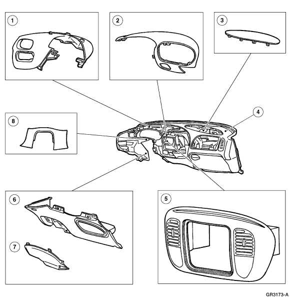
Many online platforms provide extensive repositories of illustrations tailored to various vehicle models. These can often be found on official manufacturer websites or specialized automotive forums. By taking advantage of these resources, users can not only enhance their understanding but also make informed decisions when sourcing authentic components, ultimately leading to more successful repairs and enhancements.
Digital vs. Printed Diagrams
The choice between electronic formats and physical copies is increasingly relevant in today’s technical landscape. Each format offers unique advantages and challenges that cater to different preferences and needs.
Advantages of Digital Formats
Electronic versions provide easy access, allowing users to zoom in for detail and search for specific components quickly. They often include interactive features, enhancing the user experience and enabling quick updates to information.
Benefits of Printed Copies
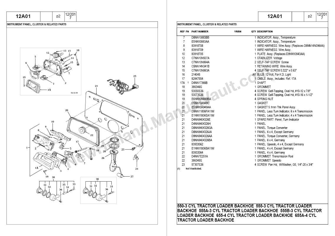
Physical documents offer tangible accessibility, making them easy to reference in environments where screens may be impractical. Additionally, they can be used without the need for electronic devices, ensuring usability in various settings.
Tools for Accessing Parts Diagrams
To effectively navigate and identify components within a mechanical system, various resources are available to assist enthusiasts and professionals alike. These tools enhance understanding and streamline the process of locating necessary items.
Online Databases: Numerous websites offer comprehensive catalogs, making it easy to search for specific elements using model numbers or descriptions.
Mobile Applications: Many apps provide on-the-go access to detailed schematics and can be invaluable during repairs or maintenance.
User Manuals: Official guides often include visual references that simplify the identification of components, ensuring accuracy in any task.
Community Forums: Engaging with fellow users in dedicated online communities can yield insights and shared resources, allowing for collaborative problem-solving.
Utilizing these resources can greatly enhance efficiency and effectiveness in identifying and acquiring essential items.
Common Mistakes When Reading Diagrams
Understanding technical illustrations can be challenging. Many individuals overlook key elements, leading to misinterpretations and potential errors in application. Here are some frequent pitfalls to avoid.
Ignoring Legends and Symbols
One of the most common errors is disregarding the accompanying legends and symbols. These elements provide essential information for accurate comprehension.
- Assuming symbols have universal meanings.
- Failing to reference the legend before interpreting the visual.
Overlooking Connections and Relationships
Many users miss crucial connections between components. This oversight can significantly alter the intended understanding.
- Not tracing paths or flows accurately.
- Ignoring annotations that clarify relationships.
How Diagrams Aid in Maintenance
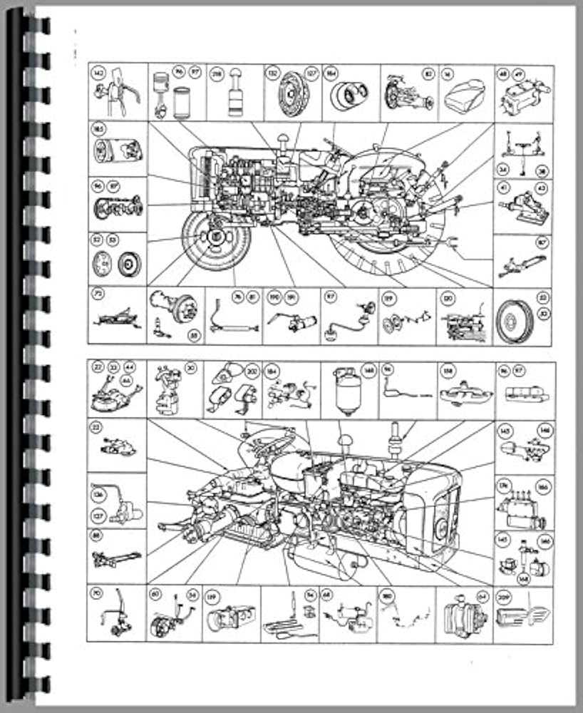
Visual representations play a crucial role in the upkeep of vehicles, offering a clear roadmap for both professionals and enthusiasts. By breaking down complex assemblies into understandable sections, these illustrations facilitate easier identification of components and their functions.
When technicians encounter issues, having access to these visuals allows for quick reference, streamlining troubleshooting processes. Instead of relying solely on memory or descriptions, they can pinpoint exact locations and arrangements, reducing the likelihood of errors.
Additionally, these tools enhance communication among team members. When discussing repairs or replacements, referring to a shared visual can eliminate misunderstandings, ensuring everyone is aligned on the task at hand. This collaborative approach not only improves efficiency but also fosters a more informed work environment.
In summary, the use of graphical representations is essential in maintenance practices, providing clarity, precision, and improved collaboration, all of which contribute to the longevity and reliability of vehicles.
Comparing Diagrams Across Ford Models
When examining the intricate layouts of various vehicle models, a fascinating comparison emerges. Each design reflects the unique engineering principles and aesthetic choices made by the manufacturer, highlighting both similarities and distinct features. Understanding these variations can provide valuable insights into performance, maintenance, and compatibility across different vehicles.
As we delve deeper, it’s essential to consider how specific components are arranged and function within each model. Variations in size, placement, and technology often lead to significant differences in efficiency and user experience. This exploration not only enhances knowledge but also aids in making informed decisions regarding repairs and upgrades.
Ultimately, recognizing the nuances in these layouts can enrich one’s appreciation for automotive engineering. By analyzing how different models approach similar challenges, enthusiasts and technicians alike can better navigate their vehicles’ intricacies and optimize their performance.
Future Trends in Parts Documentation
The evolution of documentation for components is on the brink of significant transformation, driven by technological advancements and user needs. As industries embrace innovation, the methods for accessing and understanding these materials are set to become more efficient and interactive.
- Augmented Reality: Enhancing user experience by overlaying digital information onto physical objects.
- Cloud-Based Platforms: Allowing seamless updates and access from anywhere, promoting collaboration.
- Artificial Intelligence: Automating searches and personalizing content to meet user requirements.
- Interactive Visuals: Providing dynamic representations to facilitate comprehension and usability.
These trends are poised to revolutionize how individuals engage with documentation, ultimately leading to improved efficiency and satisfaction.