Honda BF75 Parts Overview and Diagram
honda bf75 parts diagram

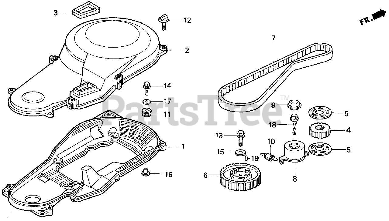
When working with any mechanical system, knowing the layout of its essential elements can greatly simplify maintenance and repairs. Being familiar with how different units connect and operate together helps to identify issues and ensure efficient operation over time.

In this context, visual representations serve as a critical resource, offering a clear overview of each individual component’s place within the broader system. By understanding these relationships, users can approach tasks with greater confidence and accuracy.

Whether for routine upkeep or more complex repairs, having access to detailed layouts of the internal systems can save time and effort, ensuring that each step in the process is properly executed.

Honda BF75 Parts Diagram Overview

The visual representation of the internal components and systems is essential for understanding how each section of the equipment operates. This schematic layout allows users to identify individual elements and comprehend their relationship within the larger structure, facilitating maintenance and repair efforts.

Component Breakdown

Each segment of the machinery is displayed in a clear and structured way, offering a comprehensive look at the key units. Users can easily follow the connections between various sections, ensuring a smooth process when replacing or servicing specific elements.

Efficient Maintenance Guide

By using the detailed illustration, identifying specific elements becomes significantly easier, which minimizes the time spent on troubleshooting and helps in ensuring that the correct procedures are followed during repair work. This enhances the overall reliability and longevity of the equipment.

Understanding the Main Engine Components
honda bf75 parts diagram

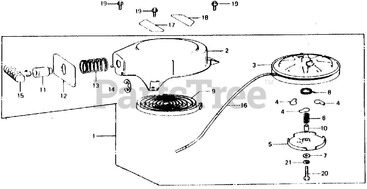
To keep a marine engine running efficiently, it’s essential to have a clear understanding of its key elements. Each component plays a vital role in the overall performance, ensuring smooth operation and durability. Familiarizing yourself with these elements allows for better maintenance and troubleshooting when needed.

Cylinder Block: This is the foundation of the engine, housing critical elements that contribute to the power generation process. It’s designed to endure high pressure and heat, providing structural support.

Pistons and Crankshaft: These components convert fuel into motion. The pistons move within the cylinder block, while the crankshaft transforms their vertical motion into rotational energy, which powers the engine.

Cooling System: To prevent overheating, the cooling system ensures that the engine maintains optimal temperature during operation. This system uses water or air to dissipate heat, keeping everything within safe limits.

Fuel and Air Intake: For combustion to occur, the engine requires a balanced mix of fuel and air. The intake system delivers these elements into the

Exploring the Fuel System Layout

The fuel system is a critical component in ensuring smooth and efficient engine operation. Understanding its structure and how the different elements work together is essential for maintaining optimal performance. This section will cover the primary components of the system and their functions, offering insights into how each part contributes to fuel delivery and combustion.

Main Components

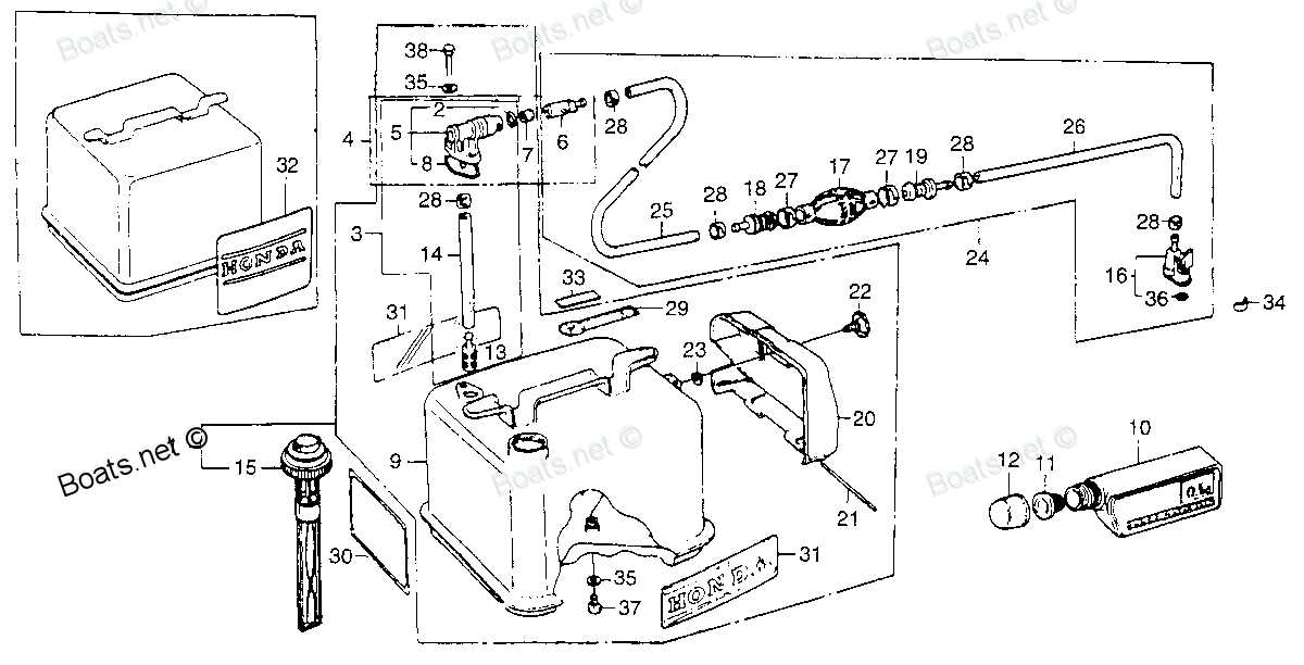
The fuel system consists of various interconnected elements designed to store, filter, and deliver fuel to the engine. These include the tank, filters, lines, and pumps. Together, they ensure the engine receives a steady and clean supply of fuel, preventing potential issues such as clogging or air intake interruptions.

Fuel Flow Path

Fuel travels through a series of channels, beginning from the storage tank and passing through several filters and pumps before reaching the engine. Each stage is crucial for removing contaminants and maintaining proper pressure, ensuring efficient combustion and engine performance.

Component

Cooling System Structure and Parts

The cooling system ensures that the engine operates at an optimal temperature by circulating coolant through key areas. Proper temperature regulation prevents overheating and enhances overall performance, maintaining a stable engine environment.

Key components include the water pump, which drives the coolant flow, and the thermostat, responsible for adjusting the coolant circulation based on engine temperature. Additionally, passages within the engine and an external radiator facilitate heat exchange, ensuring the removal of excess heat.

Effective operation of the cooling system is crucial for prolonging engine life and preventing potential malfunctions due to thermal stress. Regular checks and maintenance of this system contribute to efficient engine performance.

Electrical Wiring and Key Connections

honda bf75 parts diagram

Understanding the electrical layout and vital connections is essential for maintaining functionality and ensuring that all systems operate smoothly. Properly installed wiring can help prevent common issues and ensure long-term reliability.

Wiring Overview

The wiring setup consists of several core elements that link together the main electrical components. It’s important to keep these connections secure to avoid interruptions in electrical flow. Whether you’re connecting the ignition, lighting, or control systems, attention to detail ensures a seamless power supply throughout.

Main Connections

honda bf75 parts diagram

Key connections within the wiring system are the lifelines that provide power and communication between different modules. Proper attachment of these connectors is crucial to maintaining signal integrity and power distribution.

Connection Type Function
Ignition Connection Ensures the starting system operates correctly.
Battery Terminal Supplies power to all electrical components.
Ground Connection Detailed Breakdown of the Propeller Assembly

The propeller assembly plays a crucial role in the efficiency and performance of marine vessels. Understanding its components and how they interact can greatly enhance maintenance and operational practices. This section delves into the various elements of the propeller assembly, highlighting their functions and significance in ensuring smooth navigation.

Key Components

honda bf75 parts diagram

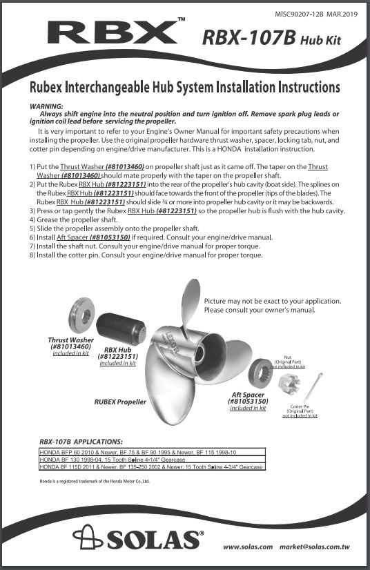
The primary elements of the propeller assembly include the blades, hub, and shaft. Each blade is designed to generate thrust by converting rotational energy into forward motion. The hub serves as the central connection point, holding the blades securely while allowing for rotation. The shaft transmits power from the engine to the propeller, playing a vital role in overall propulsion.

Maintenance Considerations

Regular inspection and maintenance of the propeller assembly are essential for optimal performance. Check for signs of wear and corrosion, as these can significantly impact efficiency. Proper alignment of the shaft and securing the hub are critical steps in ensuring that the propeller operates smoothly and reliably.

Lower Unit Assembly: Key Parts Explained

The lower unit assembly of an outboard motor plays a crucial role in its overall functionality and efficiency. This section will delve into the essential components that constitute this assembly, highlighting their functions and significance in the operation of the engine.

Essential Components

  • Gearcase: This houses the drive gears and is integral to transmitting power from the engine to the propeller.
  • Propeller Shaft: The shaft connects the gearcase to the propeller, allowing for effective propulsion.
  • Water Pump: Vital for cooling, this component draws water from the surrounding environment to prevent overheating.
  • Trim Tab: This adjustable plate helps stabilize the boat’s attitude and improve handling.
  • Seal Kit: These seals prevent water and debris from entering the lower unit, ensuring longevity and reliability.

Functionality of Key Parts

  1. The gearcase is designed to withstand significant forces, ensuring smooth gear engagement.
  2. Through the propeller shaft, rotational energy is efficiently transferred to the propeller, creating thrust.
  3. The water pump circulates coolant to maintain optimal engine temperatures, enhancing performance.
  4. The trim tab allows the operator to make minor adjustments for better stability and efficiency while navigating.
  5. Regular maintenance of the seal kit is necessary to avoid costly repairs due to water intrusion.

How to Identify Gaskets and Seals

Understanding how to recognize various types of gaskets and seals is crucial for maintaining the efficiency and longevity of mechanical systems. These components play a vital role in preventing leaks and ensuring proper functioning by providing a tight barrier between surfaces. Familiarity with their characteristics can aid in proper selection and replacement, which is essential for optimal performance.

Examine the Material: Gaskets and seals are made from different materials, each suited for specific applications. Common options include rubber, silicone, and cork. Knowing the material can help you determine the suitable use and compatibility with the fluids or gases they will encounter.

Check the Shape and Size: The configuration of gaskets and seals varies significantly. Pay attention to the dimensions and outline, as these factors are critical for a proper fit. Measure the diameter and thickness where applicable, and compare them to specifications to ensure accuracy.

Look for Signs of Wear: Inspecting for wear and damage can provide insights into the condition of these components. Cracks, tears, or distortion often indicate that a gasket or seal is no longer effective and needs replacement. Regular checks can prevent more severe issues down the line.

Ignition System Components and Placement

The ignition system is a critical element in ensuring the efficient operation of any internal combustion engine. Its primary role is to ignite the air-fuel mixture within the combustion chamber, thereby initiating the engine’s power cycle. Understanding the various components involved and their specific locations can greatly aid in troubleshooting and maintenance tasks.

Key Components of the Ignition System

honda bf75 parts diagram

This system typically comprises several essential parts, including the ignition coil, spark plugs, distributor, and wiring harness. Each component plays a distinct role: the ignition coil transforms low voltage from the battery into high voltage; the spark plugs ignite the air-fuel mixture; the distributor directs the electrical current to the correct cylinder; and the wiring harness connects all components, ensuring proper functionality.

Placement Considerations

The arrangement of these elements is vital for optimal performance. The ignition coil is usually mounted close to the battery for efficient power supply, while the distributor is strategically located to minimize the length of the wiring. Spark plugs are positioned within the engine block, ensuring immediate contact with the combustion chamber. Proper placement helps reduce voltage loss and enhances the overall efficiency of the ignition system.

Throttle Control and Linkage Parts Guide

The throttle control mechanism plays a crucial role in regulating engine performance, ensuring smooth acceleration and deceleration. This system consists of various components that work together to translate the operator’s inputs into precise adjustments in engine speed. Understanding these elements is essential for effective maintenance and troubleshooting.

The primary component of the throttle control is the throttle lever, which allows the operator to manipulate engine speed effortlessly. Connected to this lever is a series of linkages, including rods and cables, that facilitate the transmission of movement. These linkages are designed to provide a direct connection between the throttle lever and the throttle valve, ensuring optimal responsiveness.

Additionally, various springs and connectors are integral to the throttle assembly. Springs are typically employed to return the throttle to its default position when the operator releases the lever, preventing unintended acceleration. Connectors play a vital role in securing the components, ensuring they function harmoniously without excessive wear or misalignment.

Regular inspection of these components is essential for maintaining the efficiency of the throttle control system. Over time, wear and tear may affect the performance of the linkages, leading to potential issues such as sticking or erratic throttle response. By understanding the function and arrangement of these elements, operators can make informed decisions about maintenance and repairs, ultimately enhancing the overall performance of the engine.

Maintaining the Gearbox: Parts Reference

Ensuring the longevity and efficiency of a transmission system requires regular attention to its components. Each element plays a crucial role in the overall performance and reliability of the mechanism. Understanding the various elements involved can aid in effective upkeep and troubleshooting.

The transmission assembly comprises several key components, including the casing, gears, and seals. Each part must be inspected for wear and tear, as they directly affect the operation of the system. Regular lubrication is essential to minimize friction and prevent overheating.

In addition to routine checks, replacing worn or damaged components is vital for maintaining optimal functionality. Consulting a comprehensive reference guide can facilitate the identification of necessary replacements and ensure that the right parts are utilized during repairs.

Overall, a proactive approach to maintaining the gearbox will enhance its performance and extend its service life, ultimately contributing to smoother operation and reliability.