Comprehensive Guide to the International 240 Parts Diagram
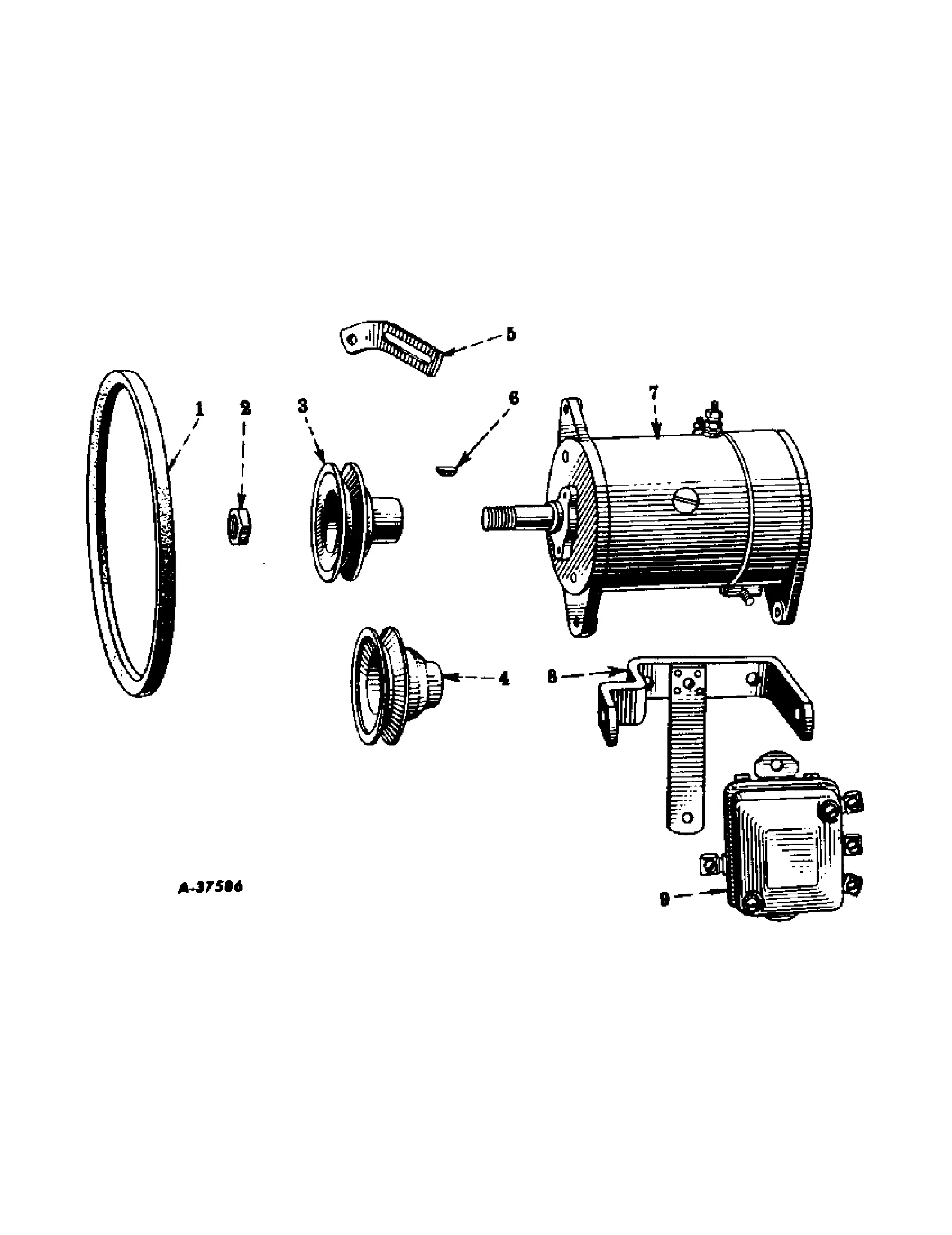
In the realm of mechanical engineering, the visualization of various machine components is crucial for effective maintenance and troubleshooting. A clear representation of the arrangement and functionality of these elements enables technicians and operators to navigate complexities with greater ease. By dissecting these intricate systems, users can enhance their understanding and operational efficiency.
Whether dealing with agricultural vehicles or industrial equipment, recognizing how individual pieces fit together is essential. Each element plays a pivotal role in the overall performance of the machinery, and an organized layout helps in identifying potential issues swiftly. This knowledge not only facilitates repairs but also aids in preventive measures, ensuring longevity and optimal functionality.
The following exploration will delve into the specifics of these component layouts, providing insights that are vital for anyone involved in the upkeep or operation of heavy machinery. By examining the various elements and their interactions, users can cultivate a deeper appreciation for the engineering behind these robust systems.
Understanding the International 240 Parts Diagram
Grasping the components of machinery is crucial for effective maintenance and repair. A detailed visual representation can significantly aid in identifying individual elements and their interconnections, enabling users to enhance their familiarity with the equipment.
Such a schematic serves as a roadmap, illustrating various sections and components, which can be especially helpful for troubleshooting and assembly. Knowing how each piece fits together ensures smoother operations and extends the longevity of the machinery.
| Component | Description |
|---|---|
| Engine | The primary power source, crucial for operation. |
| Transmission | Facilitates the transfer of power to the wheels. |
| Chassis | The framework that supports all other components. |
| Hydraulic System | Controls lifting and other functions through fluid pressure. |
| Electrical System | Powers lighting and electronic controls. |
By understanding each component’s role and location, operators can effectively address issues, perform routine checks, and make informed decisions about repairs and replacements.
Overview of the International 240 Tractor
This section provides a comprehensive look at a classic agricultural machine renowned for its reliability and efficiency in the field. With a robust design and versatile functionality, this vehicle has become a staple for farmers and contractors alike. Its impressive specifications and user-friendly features make it an invaluable asset for a wide range of tasks.
Designed for optimal performance, this model offers a blend of power and ease of operation. The following table outlines its key characteristics:
| Feature | Description |
|---|---|
| Engine Type | Four-cylinder gasoline or diesel engine |
| Horsepower | Approximately 30-35 HP |
| Transmission | Manual with multiple gears for improved control |
| Weight | Around 3,000 lbs |
| Fuel Capacity | 12 gallons |
| Wheelbase | 74 inches |
In summary, this agricultural vehicle is characterized by its durability, efficiency, and ease of use, making it an essential tool for various farming operations.
Key Components Explained
This section delves into the essential elements that contribute to the functionality and efficiency of machinery. Understanding these components is crucial for maintenance and optimal performance. Each part plays a specific role in ensuring that the entire system operates smoothly, highlighting the importance of knowledge in troubleshooting and repairs.
Core Elements
The fundamental parts of a mechanical system can vary, but several core elements are commonly found across different models. These include the engine, transmission, and hydraulic systems, each contributing to the overall functionality.
| Component | Description |
|---|---|
| Engine | The powerhouse that converts fuel into mechanical energy, driving the entire machine. |
| Transmission | Responsible for transferring power from the engine to the wheels, allowing for movement. |
| Hydraulic System | Facilitates the movement of various components through fluid pressure, enabling lifting and steering. |
Additional Components
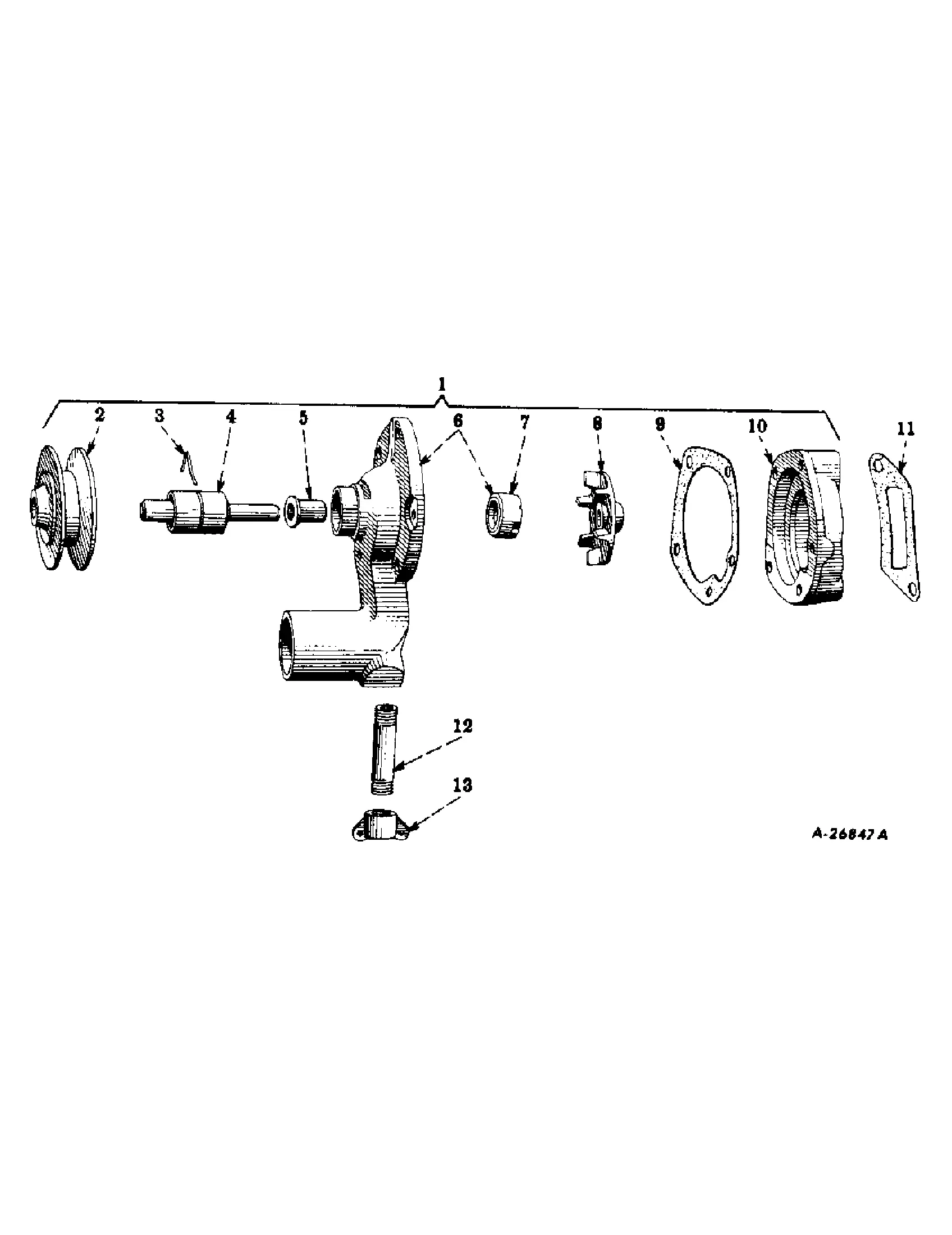
Beyond the core elements, there are other significant parts that enhance performance and usability. These include electrical systems, braking mechanisms, and cooling systems, which work in harmony with the main components.
| Component | Description |
|---|---|
| Electrical System | Controls lighting, ignition, and other electronic functions essential for operation. |
| Braking Mechanism | Ensures safe stopping and control by applying friction to the wheels. |
| Cooling System | Prevents overheating by regulating the temperature of the engine. |
Importance of Accurate Diagrams
Precise illustrations play a crucial role in various technical fields, serving as essential tools for understanding complex systems. They provide a clear representation of components, facilitating communication among engineers, technicians, and users. The accuracy of these visual aids directly impacts maintenance, troubleshooting, and assembly processes.
Enhanced Understanding
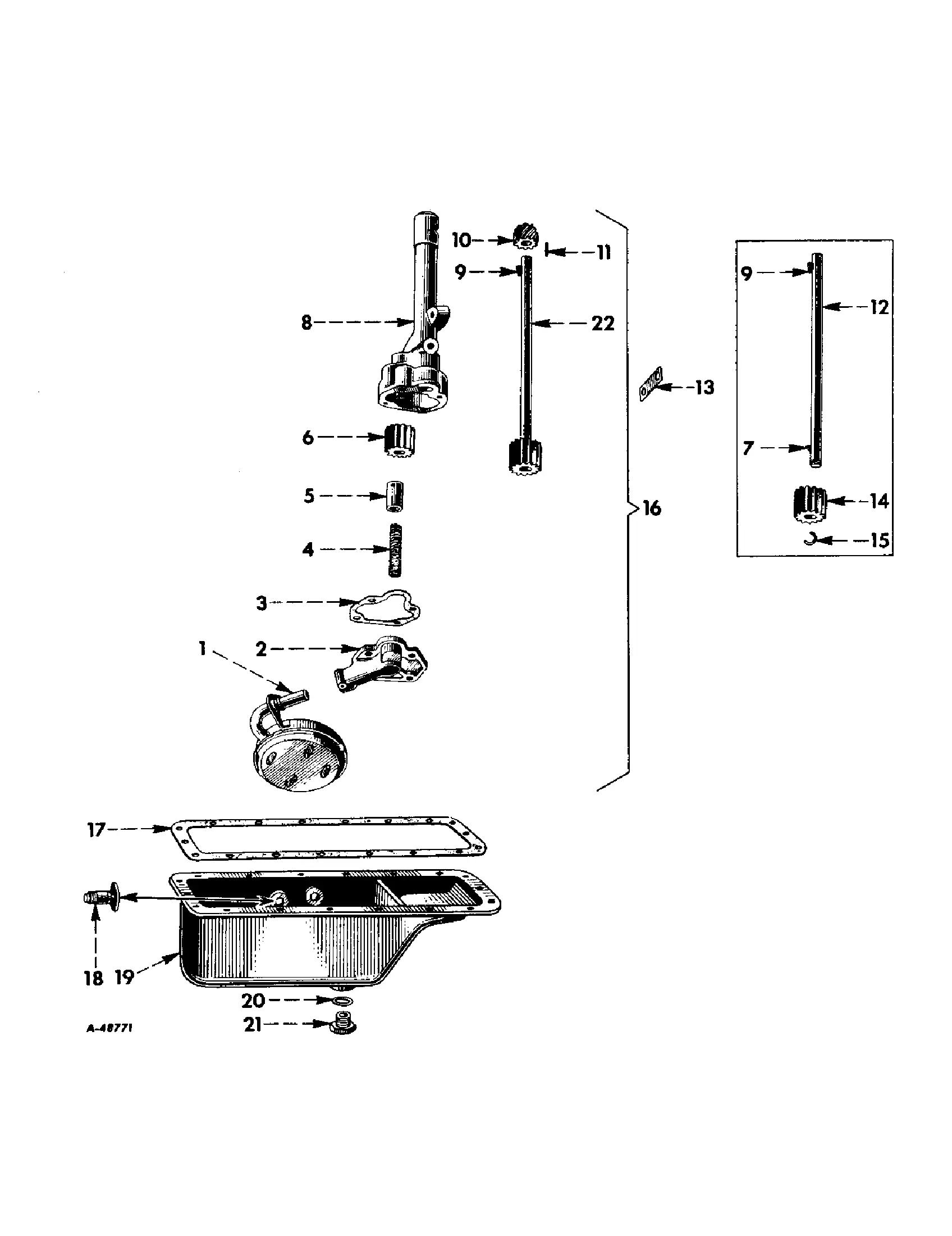
Clear and detailed representations contribute to a deeper comprehension of mechanisms and workflows. When individuals can visualize the arrangement and function of elements, they are better equipped to address challenges efficiently. Accurate representations minimize confusion and errors, leading to improved performance in operational tasks.
Efficient Troubleshooting
In the event of malfunction, reliable illustrations serve as invaluable references. They allow users to quickly locate issues and implement solutions, significantly reducing downtime. By relying on well-crafted visuals, teams can streamline their repair processes, ensuring that systems remain operational and effective.
Common Repairs and Maintenance Tips
Regular upkeep and timely repairs are essential for prolonging the lifespan and efficiency of machinery. Understanding the common issues that can arise and knowing how to address them can save time and money in the long run. Below are some essential practices to consider for maintaining optimal performance.
Routine Checks
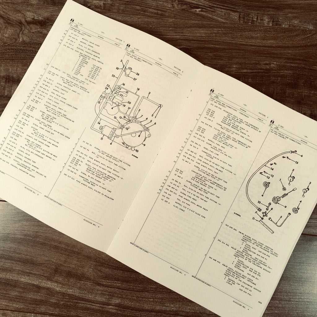
- Inspect fluid levels regularly, including oil, coolant, and hydraulic fluids.
- Examine belts and hoses for signs of wear or damage.
- Check tire pressure and tread condition to ensure proper traction and safety.
Basic Repairs
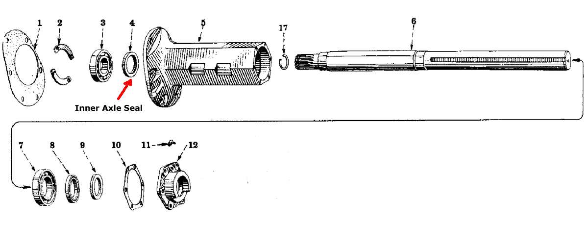
- Replace filters as needed to maintain air and fuel quality.
- Tighten loose bolts and connections to prevent further mechanical issues.
- Address leaks promptly to avoid significant damage or performance loss.
By following these guidelines, operators can enhance performance and minimize the risk of breakdowns, ensuring that their equipment operates efficiently for years to come.
Where to Find Replacement Parts
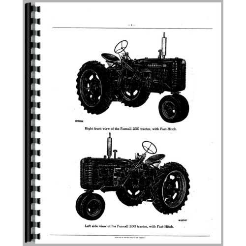
Locating components for machinery can be a challenging task, but several reliable sources can simplify the process. Whether you are in need of a specific element or a general overhaul, understanding where to look can save time and money. Various outlets offer both new and refurbished items, catering to diverse needs and budgets.
Online Retailers
The internet provides a vast array of options for sourcing components. Numerous e-commerce platforms specialize in machinery supplies, making it easy to search for specific items. Here are some popular online retailers:
| Website | Specialty |
|---|---|
| Example1.com | New and aftermarket components |
| Example2.com | Refurbished equipment and accessories |
| Example3.com | Manufacturer surplus and closeouts |
Local Suppliers
In addition to online options, local distributors often carry a range of items. Building relationships with nearby suppliers can lead to better deals and more immediate access to needed goods. Check local listings or community boards for recommendations.
Interpreting the Parts Diagram
Understanding the layout of components is essential for effective maintenance and repairs. Each illustration serves as a visual guide, allowing users to identify various elements and their relationships within the overall system. This clarity aids in troubleshooting, assembly, and disassembly tasks.
When examining the schematic, it is crucial to pay attention to the labels and numbers associated with each element. These identifiers provide insight into specific functionalities and help in sourcing replacements or upgrades. Familiarity with the arrangement will streamline the process of working with the machinery.
Moreover, recognizing the grouping of related components can enhance comprehension of how different parts interact. This knowledge is invaluable for diagnosing issues, as it highlights potential areas where malfunctions may occur. A thorough grasp of the visual representation leads to more efficient problem-solving and a better understanding of the equipment’s operation.
In conclusion, mastering the interpretation of these illustrations empowers users to engage more confidently with their machinery. It transforms complex tasks into manageable steps, fostering a deeper connection with the equipment and enhancing overall performance.
Visualizing Assembly and Disassembly
Understanding the intricate process of putting together and taking apart machinery can greatly enhance efficiency and maintenance. This segment focuses on the importance of visual aids in comprehending how components fit and function together. By employing clear illustrations, operators can gain a deeper insight into each step of the procedure, ensuring accuracy and minimizing errors.
Utilizing visual representations allows for a more intuitive grasp of the assembly line. Each piece can be easily identified and understood in relation to others, facilitating a smoother workflow. Effective visualization not only speeds up the process but also aids in troubleshooting potential issues during disassembly. When workers can see how parts interact, they are better equipped to handle repairs or replacements.
Incorporating diagrams that highlight connection points and sequences fosters a clearer understanding of mechanical relationships. This clarity is crucial for both novice and experienced personnel, as it reduces the likelihood of confusion during assembly tasks. Ultimately, well-designed visual aids serve as invaluable tools in promoting safety and operational proficiency.
Comparing with Other Models
Understanding the nuances between different agricultural machines can significantly impact operational efficiency and maintenance strategies. Each model offers unique features, performance metrics, and design philosophies, making it essential to evaluate them in context. This section delves into how one specific model aligns or contrasts with others in the same category, providing insights into their respective advantages and disadvantages.
| Feature | Model A | Model B | Model C |
|---|---|---|---|
| Engine Power | 75 HP | 85 HP | 70 HP |
| Weight | 3200 lbs | 3500 lbs | 3000 lbs |
| Fuel Efficiency | 5.0 L/h | 4.8 L/h | 5.2 L/h |
| Turning Radius | 10 ft | 12 ft | 9 ft |
| Maintenance Interval | 100 hrs | 150 hrs | 120 hrs |
By examining these characteristics, operators can make informed decisions that align with their specific needs and operational goals. Such comparisons help in understanding not just performance but also the overall value each machine brings to the field.
Resources for Troubleshooting Issues
When facing operational difficulties with machinery, having access to the right resources can make all the difference. A systematic approach to problem-solving can help identify and rectify malfunctions effectively. Here, we present various tools and materials that can aid in diagnosing and resolving common concerns.
Online Forums and Communities
Engaging with online platforms dedicated to machinery enthusiasts can provide valuable insights. These communities often share personal experiences and solutions to similar problems.
Technical Manuals and Guides
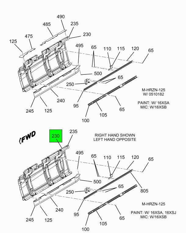
Detailed manuals and instructional guides are essential for understanding the intricacies of any machine. They typically include troubleshooting sections that outline common issues and their remedies.
| Resource Type | Description | Benefits |
|---|---|---|
| Online Forums | Discussion platforms for user experiences | Real-world solutions and advice |
| Technical Manuals | Comprehensive documentation for machinery | Step-by-step troubleshooting assistance |
| Video Tutorials | Visual guides on repairs and maintenance | Demonstrates techniques effectively |
| Manufacturer Support | Official help from machine makers | Access to expert knowledge and resources |
Utilizing Online Forums and Communities
Engaging with virtual communities can significantly enhance knowledge sharing and problem-solving for enthusiasts and professionals alike. These platforms offer a wealth of information, ranging from troubleshooting tips to detailed discussions on maintenance and upgrades. By participating in these discussions, individuals can connect with like-minded people and tap into a rich resource of collective expertise.
Benefits of Community Participation
Joining online groups allows members to access diverse perspectives and solutions. Some advantages include:
| Advantage | Description |
|---|---|
| Knowledge Sharing | Members often share their experiences and insights, providing valuable information that may not be readily available in manuals. |
| Real-time Support | Forums provide instant feedback from fellow users, making it easier to resolve issues quickly. |
| Networking Opportunities | Connecting with other enthusiasts can lead to collaborations and friendships, enhancing the overall experience. |
Finding the Right Communities
To maximize benefits, it’s essential to choose the right platforms. Look for active forums with a positive atmosphere where members are willing to help. Additionally, consider joining social media groups or specialized websites that focus on your interests to further broaden your horizons.
Best Practices for Maintenance Documentation
Effective maintenance documentation is crucial for ensuring the longevity and reliability of machinery. It serves as a comprehensive guide for technicians and operators, enabling them to perform their tasks efficiently and accurately. By adhering to certain best practices, organizations can enhance the clarity and usefulness of their maintenance records.
- Standardization: Use consistent terminology and formats throughout your documentation. This reduces confusion and allows for easier reference.
- Detail Orientation: Include all relevant information such as model numbers, maintenance schedules, and specific procedures. This thoroughness aids in understanding the requirements.
- Visual Aids: Incorporate diagrams, charts, and images when applicable. Visual representations can simplify complex processes and enhance comprehension.
Regular updates are essential for keeping documentation accurate and relevant. As equipment changes or new procedures are implemented, records should reflect these adjustments promptly.
- Periodic Reviews: Schedule regular evaluations of the documentation to ensure it aligns with current practices and standards.
- Training and Accessibility: Ensure all relevant personnel are trained on how to use the documentation effectively and that it is easily accessible.
- Feedback Mechanism: Establish a system for users to provide input on the documentation. This can highlight areas for improvement and promote continuous enhancement.
By implementing these strategies, organizations can create a robust framework for maintenance documentation that supports operational efficiency and minimizes downtime.