Kubota B2920 Parts Diagram Overview
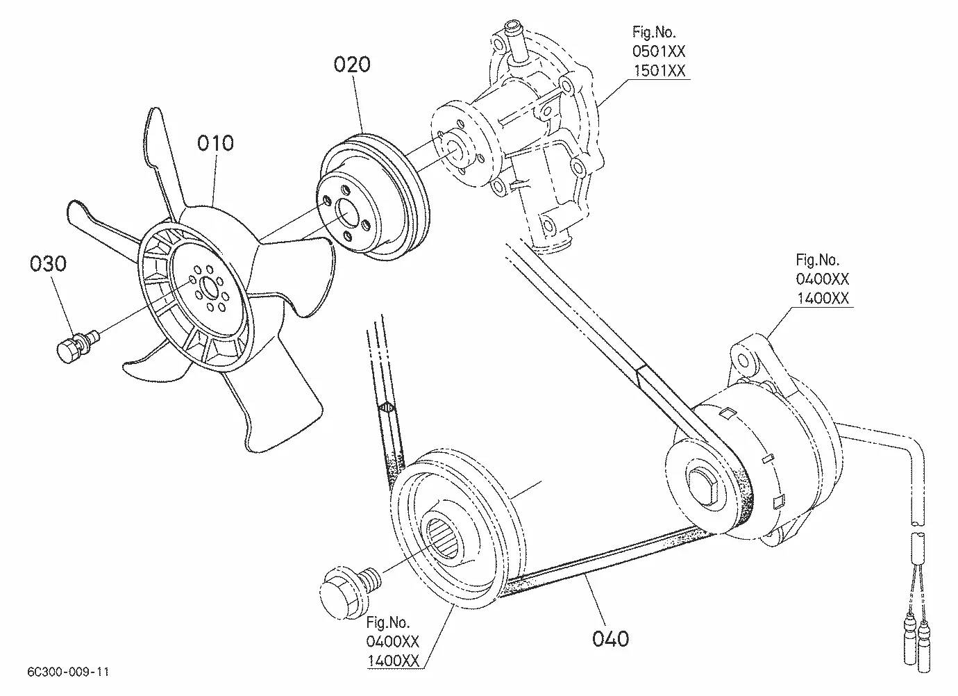
For those working with agricultural machinery, having a clear overview of system components is crucial for both routine upkeep and troubleshooting. Whether you’re managing regular maintenance tasks or tackling unexpected issues, knowing how different elements fit together can save time and effort. With a detailed layout of various systems, you can easily identify and locate specific components, ensuring smoother repairs and servicing.
Exploring the structure and organization of mechanical systems allows operators to maintain optimal performance. By familiarizing yourself with the internal workings, you gain the ability to diagnose problems quickly and accurately. This can extend the life of your equipment, helping it run efficiently under various conditions. A well-organized overview of essential systems provides the foundation for effective maintenance and operation.
Comprehensive Overview of Kubota B2920 Components
The machinery in question is known for its durability and efficiency, offering a wide range of features that contribute to its versatile performance. This section provides a thorough look at the primary elements that compose this equipment, emphasizing key mechanical and operational features that ensure reliability in various applications.
Engine and Transmission Elements
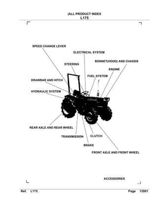
The core of the system lies in its power unit, designed for maximum fuel efficiency and consistent output. Coupled with a robust transmission system, it delivers seamless power transfer, ensuring smooth operation across different terrains and workloads.
Hydraulics and Control Systems
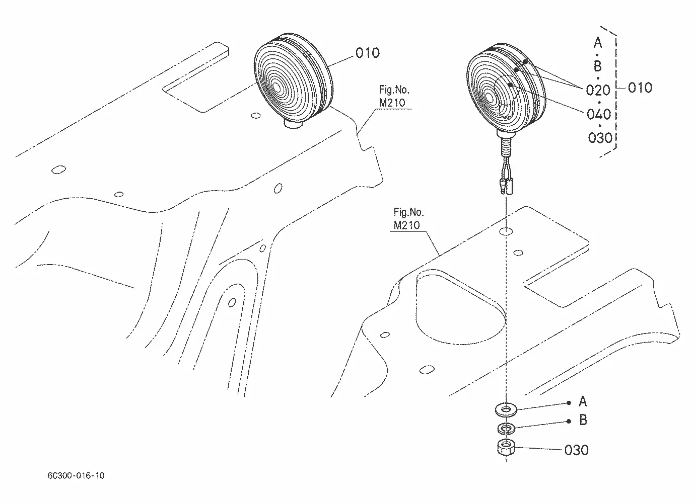
A powerful hydraulic system enables enhanced maneuverability, while the control mechanisms offer intuitive handling for the operator. This combination provides precise movements, making it suitable for both heavy-duty tasks and more delicate operations.
| Component | Description |
|---|---|
| Power Unit | High-performance motor designed for consistent output and fuel efficiency. |
| Transmission | Ensures smooth power distribution for optimal functionality across terrains. |
| Hydraulics | Advanced system for precise and powerful movement control. |
| Control System | User-friendly interface allowing intuitive machine operation. |
Key Engine Parts and Their Functions
The functionality and performance of any machine heavily rely on the synergy of its main components. Understanding how each essential element contributes to the overall operation is crucial for maintaining efficiency and longevity.
Vital Components in the Engine System
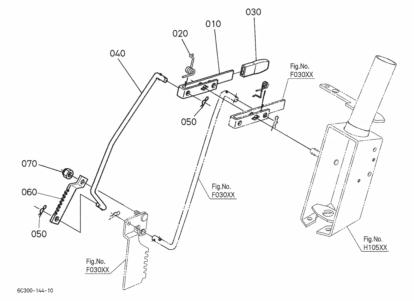
- Cylinder Block: This serves as the foundation, housing the cylinders and ensuring stability for the moving parts within the engine.
- Pistons: Pistons move up and down inside the cylinders, converting fuel combustion into mechanical energy, which powers the machine.
- Crankshaft: The crankshaft transforms the vertical motion of the pistons into rotational energy, driving other systems in the machine.
- Valves: These regulate the flow of fuel and air into the cylinders while allowing exhaust gases to exit after combustion.
- Camshaft: The camshaft controls the opening and closing of the valves, synchronizing them with the pistons for optimal combustion timing.
Additional Elements Ensuring Smooth Operation
- Fuel Injector: Delivers precise amounts of fuel into the combustion chamber, ensuring efficient energy generation.
- Oil Pump: Maintains proper lubrication by distributing
Transmission System Breakdown for Kubota B2920
The transmission system is a key component that ensures smooth and efficient power transfer, allowing the machine to operate seamlessly across different terrains and work conditions. Understanding the inner workings of this system is crucial for maintaining peak performance and extending the lifespan of the equipment.
Key components of the transmission system include gears, shafts, and clutches, each playing a vital role in managing the distribution of power from the engine. The proper alignment and synchronization of these elements are essential for smooth gear shifting and effective torque conversion.
In order to optimize performance, regular inspection and timely servicing of the transmission system are highly recommended. Worn-out gears or malfunctioning clutches can lead to reduced efficiency and even cause more serious damage to the equipment over time.
Exploring the Hydraulic Mechanism in Detail
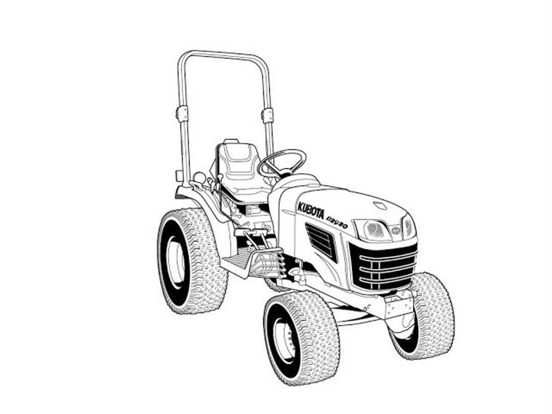
The hydraulic system plays a crucial role in managing and directing fluid power within various mechanical functions. This section delves into the structure and principles behind this vital system, explaining how it operates to ensure smooth and efficient movement and control.
Main Components of the Hydraulic System
- Pump – responsible for generating fluid flow, powering other components.
- Cylinders – convert fluid pressure into linear motion to perform lifting or pressing tasks.
- Valves – regulate the direction and flow of the hydraulic fluid.
- Reservoir – stores the hydraulic fluid and maintains proper pressure levels.
How the System Operates
When engaged, the system’s pump moves fluid from the reservoir through the valves, directing it into the cylinders. The pressurized fluid then exerts force, moving pistons or other mechanical elements. The regulation of this flow allows for precise control of movement, providing reliability in various operational contexts.
Understanding the Electrical System Configuration
The electrical system plays a vital role in ensuring efficient operation, managing energy distribution and powering various components. It is designed to handle multiple functions that range from ignition to powering lights and other essential features. To fully grasp its structure, one must explore the layout and relationships between different elements.
Key Components and Their Roles
Each part of the electrical system serves a specific purpose. Understanding these roles can provide insight into the overall configuration and help in troubleshooting issues. Below is a simplified overview of the core elements.
Component Function Battery Provides electrical energy to start the engine and power accessories. Alternator Charges the battery and supplies electricity during operation. Fuses Protect the system from electrical Implement Attachments and Compatibility
The use of implement attachments can significantly expand the versatility of machinery, allowing it to handle a wide range of tasks in different environments. These tools, when properly selected, ensure that equipment can meet the demands of various projects, from land preparation to material handling.
Compatibility between the machinery and its attachments is crucial for efficient operation. Proper fitment ensures seamless performance and minimizes wear. It is essential to assess the specifications of both the equipment and the tools to ensure a safe and effective connection.
Modern advancements in technology have led to the creation of a variety of attachment systems, designed to enhance productivity and offer easy interchangeability. Understanding the compatibility requirements can help in selecting the right attachments for each task, improving overall efficiency.
Steering and Control Systems Overview
The steering and control mechanisms are essential components that ensure precise and efficient operation. These systems play a vital role in maneuvering the machine, providing the operator with the ability to direct and manage the equipment with ease and accuracy. Understanding the layout and functionality of these systems is key to maintaining smooth and safe handling.
There are several elements involved in this setup:
- Steering Wheel Mechanism: The primary interface that allows the operator to control the movement, ensuring smooth direction changes.
- Hydraulic Control System: Provides power-assisted steering, reducing the effort needed to turn and maneuver, especially under heavy loads.
- Linkage Components: These elements connect the steering controls to the wheels, transmitting the operator’s input into physical movement.
In addition to steering, control systems also include levers and pedals that govern various operational functions:
- Speed Control: Mechanisms that allow the operator to adjust the speed and direction of the machine.
- Hydraulic Lever Controls: Used to manage attachments and other hydraulic functions, adding versatility to the machine’s capabilities.
- Brake Systems
Chassis and Frame Structure Insights
The framework and chassis of a compact agricultural vehicle play a crucial role in ensuring stability, durability, and efficient operation. This essential structure provides the necessary support for various components, allowing for effective weight distribution and enhanced maneuverability. Understanding the design elements and materials used in the construction of these parts can lead to improved maintenance practices and operational performance.
Design and Materials
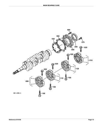
Typically, the chassis is constructed from high-strength steel or other robust materials that withstand the rigors of agricultural tasks. The design often incorporates specific geometries to enhance resistance against twisting and bending forces, which are common during operation on uneven terrains. Emphasis on durability ensures that the framework can endure long periods of heavy use while minimizing the need for frequent repairs.
Integration of Components
The frame serves as a foundational platform for various integrated systems, including the drivetrain, steering mechanism, and hydraulic components. This integration is meticulously planned to optimize space and accessibility for repairs. Understanding how these elements interact within the chassis not only aids in troubleshooting but also in upgrading or customizing the vehicle for specific tasks.
Cooling System Components and Maintenance
The efficiency of any engine largely depends on its cooling mechanism, which plays a crucial role in preventing overheating and ensuring optimal performance. Understanding the various elements involved in this system is essential for proper upkeep and functionality.
Key Components
- Radiator: Acts as a heat exchanger, dissipating heat from the engine coolant.
- Water Pump: Circulates coolant throughout the system to maintain consistent temperatures.
- Thermostat: Regulates coolant flow based on temperature, ensuring the engine reaches its optimal operating condition.
- Cooling Fans: Help increase airflow through the radiator, especially during low-speed operation.
- Hoses: Transport coolant between the engine, radiator, and other components, critical for system integrity.
Maintenance Practices
- Regularly check and replace coolant to prevent corrosion and ensure proper flow.
- Inspect hoses for wear and tear; replace any that show signs of damage.
- Examine the radiator for leaks or blockages, cleaning as necessary.
- Test the thermostat to confirm it opens and closes at the correct temperature.
- Ensure the water pump is functioning properly to maintain effective coolant circulation.
By adhering to these maintenance practices and being aware of the key components, one can significantly enhance the longevity and performance of the engine’s cooling system.
Fuel System Diagram and Parts Analysis
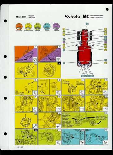
This section provides an overview of the components involved in the fuel delivery system of compact agricultural machinery. Understanding the configuration and functionality of these elements is crucial for effective maintenance and troubleshooting. The focus will be on how various elements work together to ensure efficient operation and optimal performance.
Key Components of the Fuel Delivery System
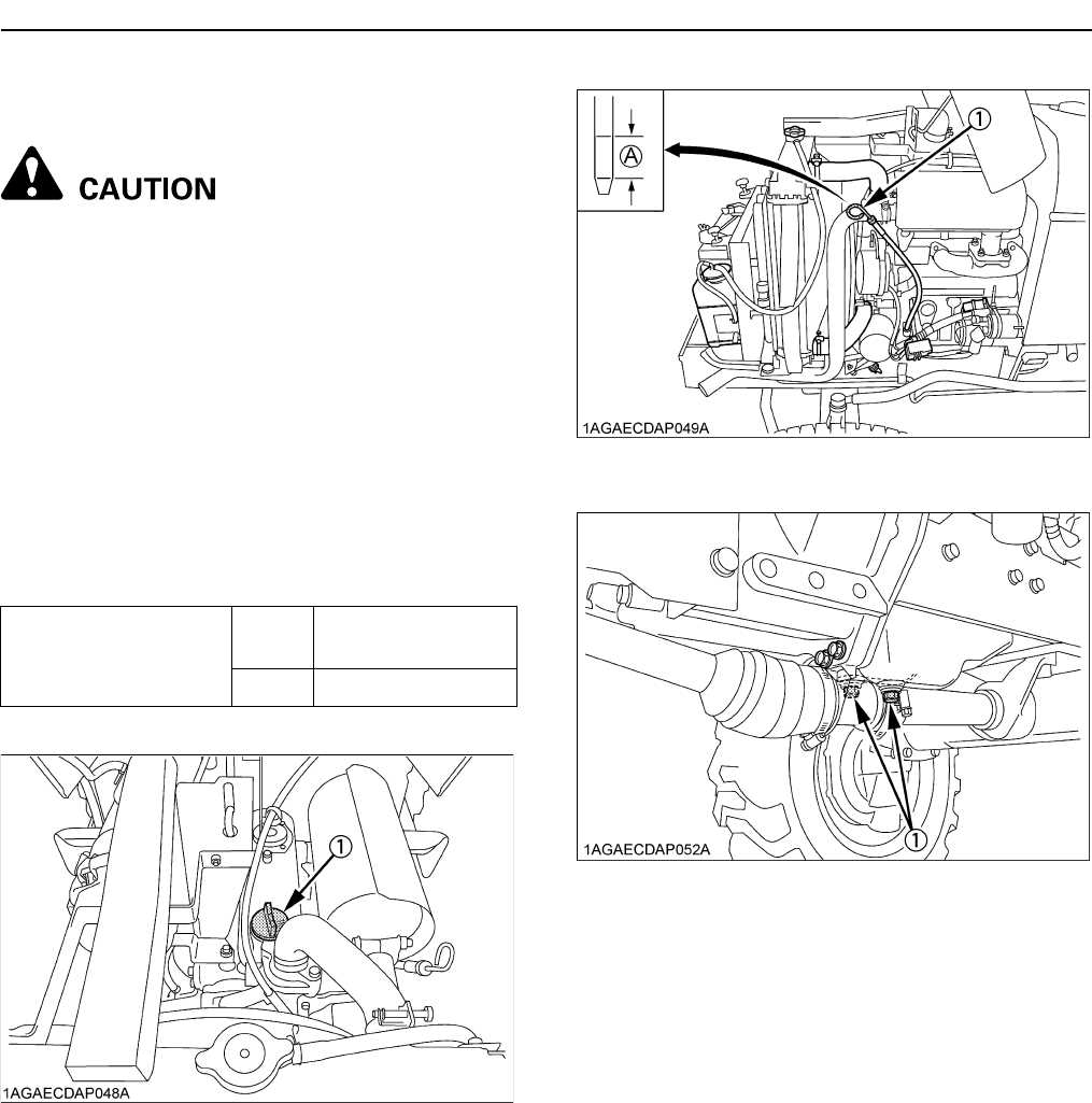
The fuel delivery mechanism is comprised of several critical elements, each playing a specific role in the overall functionality. The following table outlines these components along with their respective functions:
Component Function Fuel Tank Stores the fuel and provides a steady supply to the system. Fuel Pump Moves fuel from the tank to the engine, ensuring proper pressure. Fuel Filter Removes impurities and contaminants from the fuel before it reaches the engine. Injector Delivers a precise amount of fuel into the combustion chamber for efficient ignition. Lines and Hoses Transport fuel between the various components of the system. Conclusion
A thorough comprehension of the fuel delivery assembly is vital for maintaining the performance of agricultural machines. Regular inspection and maintenance of these components can prevent operational issues and enhance overall efficiency.
Brake System Components and Functionality
The braking mechanism of a vehicle is essential for ensuring safety and control during operation. This system comprises several key elements that work together to reduce speed or bring the machine to a complete stop. Understanding these components is crucial for maintenance and troubleshooting, as each part plays a vital role in the overall efficiency of the braking process.
Key Elements of the Braking Mechanism
At the heart of the braking system lies the master cylinder, which generates hydraulic pressure necessary for operation. This pressure is transmitted through brake lines to the brake calipers or drums, depending on the design. Brake pads or shoes then engage with the rotor or drum, creating friction that slows down the wheels. Each component must function correctly to ensure effective stopping power.
Maintenance Considerations
Regular inspection of the braking system components is crucial for preventing potential failures. Key areas to monitor include the condition of the brake fluid, wear on the pads or shoes, and the integrity of hydraulic lines. Ensuring that each element is in optimal condition enhances not only safety but also the longevity of the braking system.
Maintenance Essentials for Key Kubota B2920 Parts
Proper upkeep of essential components is crucial for optimal performance and longevity of your machinery. Regular maintenance not only enhances efficiency but also prevents costly repairs in the long run. Understanding the various elements involved in routine care can significantly contribute to the smooth operation of your equipment.
Here are some key maintenance practices to consider:
- Fluid Checks:
- Regularly inspect oil levels and quality, replacing them according to the manufacturer’s recommendations.
- Monitor coolant levels to prevent overheating and ensure efficient engine function.
- Filter Replacement:
- Change the air filter periodically to maintain proper airflow and engine performance.
- Replace fuel filters to avoid clogging and ensure a steady supply of fuel to the engine.
- Inspection of Belts and Hoses:
- Check for signs of wear, cracks, or fraying on belts and hoses, replacing them as necessary.
- Ensure proper tension in belts to avoid slippage and damage to the engine.
- Battery Maintenance:
- Inspect battery terminals for corrosion and clean them to ensure a good connection.
- Check the fluid level in the battery and top off with distilled water if needed.
By adhering to these essential maintenance practices, you can enhance the reliability and lifespan of your equipment, ensuring it remains ready for any task.
Troubleshooting Common Issues with Kubota B2920
Addressing typical problems in machinery requires a systematic approach to identify and resolve faults effectively. Regular maintenance and keen observation can help detect issues early, ensuring optimal performance and longevity of the equipment. Below are some common challenges that operators may encounter and suggested solutions to rectify them.
-
Engine Performance Issues:
- Symptoms: Rough idling, lack of power, excessive smoke.
- Solutions:
- Check fuel levels and quality.
- Inspect air filters for clogs or dirt.
- Examine spark plugs for wear and replace if necessary.
-
Hydraulic System Malfunctions:
- Symptoms: Slow or unresponsive hydraulic functions.
- Solutions:
- Inspect hydraulic fluid levels and quality.
- Check for leaks in hoses and fittings.
- Ensure the hydraulic filter is clean and not obstructed.
-
Electrical System Problems:
- Symptoms: Inconsistent starting, warning lights on the dashboard.
- Solutions:
- Examine battery connections for corrosion.
- Test the battery charge and replace if weak.
- Inspect fuses and wiring for damage.
-
Transmission Difficulties:
- Symptoms: Slipping gears, unusual noises during operation.
- Solutions:
- Check transmission fluid levels and condition.
- Inspect for leaks in the transmission casing.
- Consult the manual for adjustment procedures if needed.
By following these troubleshooting steps, operators can effectively manage and rectify common issues, ensuring that their equipment remains reliable and efficient in its operations.