Kubota KX080 4 Component Layout Overview
The internal layout of construction equipment is crucial for efficient performance and long-term reliability. By examining the mechanical components and how they interact, we can gain a deeper understanding of the machine’s operation and maintenance needs. A well-organized breakdown of these elements allows for better troubleshooting and routine service.
Identifying key sections of the machinery helps to streamline both repairs and upgrades. Whether addressing specific areas or maintaining overall functionality, knowing the exact placement of different mechanisms is essential for seamless operation.
With clear information about the arrangement of vital elements, performing preventive care becomes much easier. This clarity reduces downtime, enhances productivity, and ensures the equipment continues to perform at its best under various conditions.
Overview of Kubota KX080-4 Components
The structure of this heavy-duty machine is designed for various operational tasks, combining efficiency and durability. The system includes several interconnected elements that work together to ensure smooth performance in demanding conditions. Each unit has a specific function, contributing to the overall functionality of the machine.
- Engine Unit: The powerhouse responsible for driving the equipment, ensuring consistent power output.
- Hydraulic System: A crucial component for controlling movements and lifting capabilities, offering precision and control.
- Undercarriage: Provides stability and maneuverability, essential for working on diverse terrains.
- Cabin Features: Designed for operator comfort and control, including safety mechanisms and ergonomic controls.
- Arm and Boom Mechanism: Key parts that enable digging, lifting, and positioning tasks with ease and accuracy.
This collection of essential sections ensures the machine can perform a variety of tasks in different environments, maintaining its reliability and high operational standards.
Detailed Structure of Hydraulic System
The hydraulic system consists of various interconnected components that work together to provide efficient power transfer. This system is responsible for converting mechanical force into fluid power, which is then utilized to drive different operational functions. Understanding the arrangement of these elements is crucial for maintaining optimal performance and ensuring smooth operation.
Key components include pumps, valves, cylinders, and hoses, all of which work in unison to manage fluid pressure and flow. Each part is designed to withstand significant stress while maintaining precision in movement and force application. Regular inspection and maintenance of the hydraulic setup are vital to prevent potential failures and ensure long-term reliability.
Engine Assembly and Key Elements
The engine system serves as the core of any heavy machinery, ensuring optimal functionality and performance. This section outlines the critical components that make up the power unit, emphasizing their importance in the overall structure and operation.
Main Structural Components
The primary framework includes essential parts like the cylinder block, pistons, and crankshaft, each working in harmony to convert energy into mechanical motion. Proper alignment and maintenance of these components are crucial for efficient performance.
Supporting Systems
Supporting systems, such as the cooling mechanism and fuel supply, play a vital role in regulating the engine’s temperature and ensuring a steady flow of energy. Efficient operation of these systems prevents overheating and maintains the engine’s longevity.
Track Mechanism Breakdown and Functionality

The track mechanism of modern construction equipment is essential for ensuring stability, mobility, and control on various terrains. This section provides a detailed overview of how the system operates, focusing on the key components and their roles in the machine’s overall performance. Understanding the functionality of these parts helps in maintaining efficient operation and prolonging the machine’s lifespan.
The core of the track system consists of several interconnected elements that work together to provide smooth movement. The track itself is supported by rollers and guides that ensure proper alignment, while the drive mechanism transfers power to the track, allowing the machine to traverse rugged environments. Special attention is given to the tensioning system, which keeps the track properly adjusted to prevent wear and ensure maximum efficiency.
In addition to movement, the track mechanism plays a vital role in distributing the machine’s weight evenly, reducing ground pressure and preventing sinking on soft surfaces. This balance between mobility and stability is crucial for performing heavy-duty tasks on challenging terrain, making the track system an indispensable part of the equipment’s functionality.
Electrical System Parts and Wiring
The electrical system ensures the smooth functioning of various components and circuits that manage the equipment’s power supply. Understanding the layout and connections is crucial for maintaining reliable performance and diagnosing potential issues in the system.
Below is an outline of the main components and wiring involved in the electrical system:
- Power Source: Provides the necessary energy to the system, often regulated by a battery or an alternator.
- Control Panel: The interface that allows the operator to manage and monitor electrical functions, including ignition and lights.
- Wiring Harness: A collection of cables that connect the various electrical components, ensuring consistent energy flow and communication between systems.
- Fuses and Relays: Safety devices that protect the system from overload and ensure circuits are switched on or off as needed.
- Sensors and Switches: Provide feedback and control functions, ensuring that different parts of the machinery are operating within expected parameters.
Regular inspection and proper maintenance of these components are essential to avoid electrical failures and extend the system’s longevity.
Cabin Layout and Control Parts
The design of the operator’s environment is crucial for enhancing productivity and comfort during operation. A well-organized space allows the operator to efficiently access controls and monitors, contributing to a more intuitive and effective work experience.
Control Placement and Accessibility
Strategically positioning the controls within the cabin ensures that the operator can easily reach essential functions without excessive movement. This layout not only minimizes fatigue but also enhances safety by allowing for quicker reactions to changing conditions.
Monitoring and Instrumentation

Incorporating clear and easily readable displays within the operator’s area is vital for real-time feedback on performance and conditions. Instruments should be designed to provide essential information at a glance, allowing the operator to make informed decisions quickly and efficiently.
Cooling System Parts Arrangement
The cooling system is essential for maintaining optimal operating temperatures in heavy machinery. It comprises various components that work together to regulate heat and prevent overheating. Understanding the layout and function of these elements is crucial for effective maintenance and troubleshooting.
| Component | Description |
|---|---|
| Radiator | This component dissipates heat from the coolant, allowing it to cool before returning to the engine. |
| Water Pump | The pump circulates the coolant throughout the system, ensuring consistent flow and temperature control. |
| Thermostat | This device regulates the coolant flow based on the engine temperature, preventing it from becoming too hot or too cold. |
| Cooling Fan | The fan assists in drawing air through the radiator to enhance cooling efficiency, especially at lower speeds. |
| Hoses | Flexible tubes that transport coolant between components, maintaining proper circulation throughout the system. |
Fuel System Components and Layout

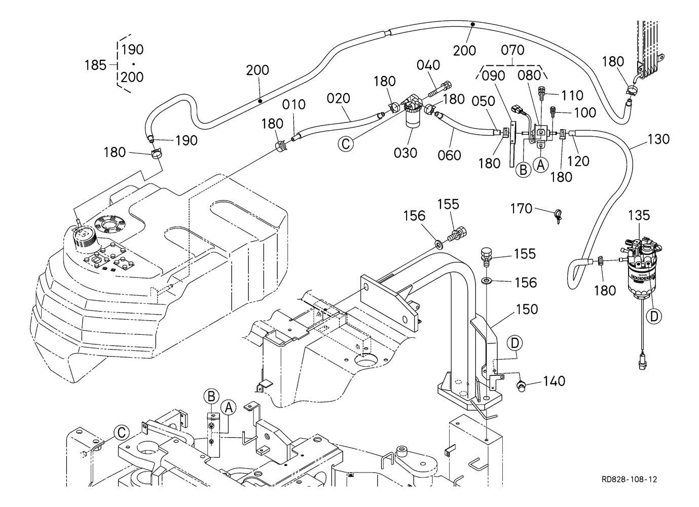
The fuel system is a critical part of any machinery, responsible for delivering the necessary energy to the engine for optimal performance. Understanding its components and their arrangement helps in maintaining efficiency and ensuring smooth operation. This section will explore the essential elements of the fuel system and their layout, providing insights into how they work together to support the overall functionality of the equipment.
Key Elements of the Fuel System
Within the fuel delivery framework, several components play pivotal roles. These include the fuel tank, pump, filters, injectors, and various hoses and fittings. Each part is designed to handle specific tasks, ensuring that clean, pressurized fuel reaches the engine without any disruptions.
System Layout Overview

The layout of the fuel system is carefully designed for efficiency and reliability. The configuration typically starts with the fuel tank, from which the fuel is drawn by a pump. The fuel then passes through filters to remove any impurities before being directed to the injectors, where it is atomized for combustion. The following table illustrates the general flow and connection of these components:
| Component | Function |
|---|---|
| Fuel Tank | Stores the fuel until needed. |
| Fuel Pump | Draws fuel from the tank and delivers it under pressure. |
| Fuel Filter | Removes contaminants from the fuel. |
| Fuel Injectors | Atomizes fuel for efficient combustion. |
| Hoses and Fittings | Connects all components and ensures proper flow. |
Undercarriage Parts and Support System

The undercarriage framework plays a crucial role in the overall functionality and stability of heavy machinery. This assembly comprises various components that work in unison to ensure the equipment operates efficiently and safely on diverse terrains. Understanding these elements is essential for effective maintenance and optimal performance.
Main Components of the Undercarriage
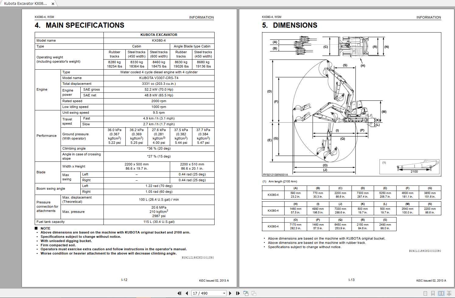
- Track Chains: These are vital for movement and traction, providing a robust connection between the vehicle and the ground.
- Sprockets: These circular components engage with the track chains to facilitate motion and ensure proper power transfer.
- Rollers: Located along the sides, they support the weight and assist in smooth navigation over surfaces.
- Idlers: These components help maintain tension in the track chains, ensuring they remain securely in place during operation.
- Frame Structure: The underlying frame offers stability and durability, supporting all other elements of the undercarriage.
Support System Features
Efficient support systems enhance the performance of the undercarriage assembly. Key features include:
- Shock Absorption: Mechanisms designed to minimize the impact from uneven surfaces, contributing to the longevity of the machinery.
- Adjustable Tensioning: Systems that allow for the fine-tuning of track tension, ensuring optimal operation under various load conditions.
- Maintenance Access Points: Strategically placed points that facilitate easy inspection and servicing of the undercarriage components.
Lubrication System Elements Breakdown
The lubrication system plays a crucial role in maintaining the efficiency and longevity of machinery. Understanding the various components involved helps ensure optimal performance and reduces wear and tear. This section provides an overview of the essential elements within the lubrication system and their functions.
| Component | Description |
|---|---|
| Oil Pump | This device circulates lubricant throughout the system, ensuring that all moving parts receive adequate coverage. |
| Oil Filter | The filter removes contaminants from the lubricant, prolonging the life of the fluid and the machinery. |
| Lubrication Lines | These conduits transport the lubricant from the pump to various components, providing necessary protection against friction. |
| Reservoir | The storage unit holds the lubricant, ensuring a sufficient supply is available for the system. |
| Pressure Relief Valve | This safety feature prevents over-pressurization in the lubrication system, protecting against potential damage. |
Exhaust System Components Diagram
The exhaust assembly of a construction machine plays a crucial role in maintaining optimal engine performance and reducing harmful emissions. Understanding the various elements of this system is essential for effective maintenance and troubleshooting. This section will provide insights into the key components and their functions, enabling users to better comprehend how the exhaust mechanism operates within the equipment.
Key Elements of the Exhaust Assembly
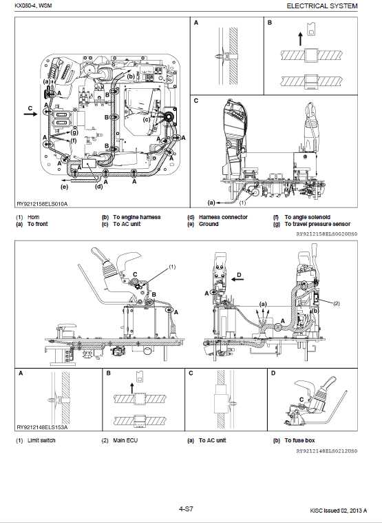
The exhaust assembly consists of several critical parts, including the manifold, muffler, and tailpipe. The manifold serves as a conduit for exhaust gases from the engine, directing them toward the muffler. The muffler is responsible for minimizing noise produced by the exhaust gases, while the tailpipe channels the gases away from the machine, ensuring proper ventilation.
Maintenance and Troubleshooting
Regular inspection of the exhaust components is vital for the longevity and efficiency of the equipment. Common issues may include blockages or leaks, which can hinder performance. By familiarizing oneself with the layout and function of the exhaust system, operators can promptly address any concerns, ensuring the machine operates smoothly and adheres to environmental standards.