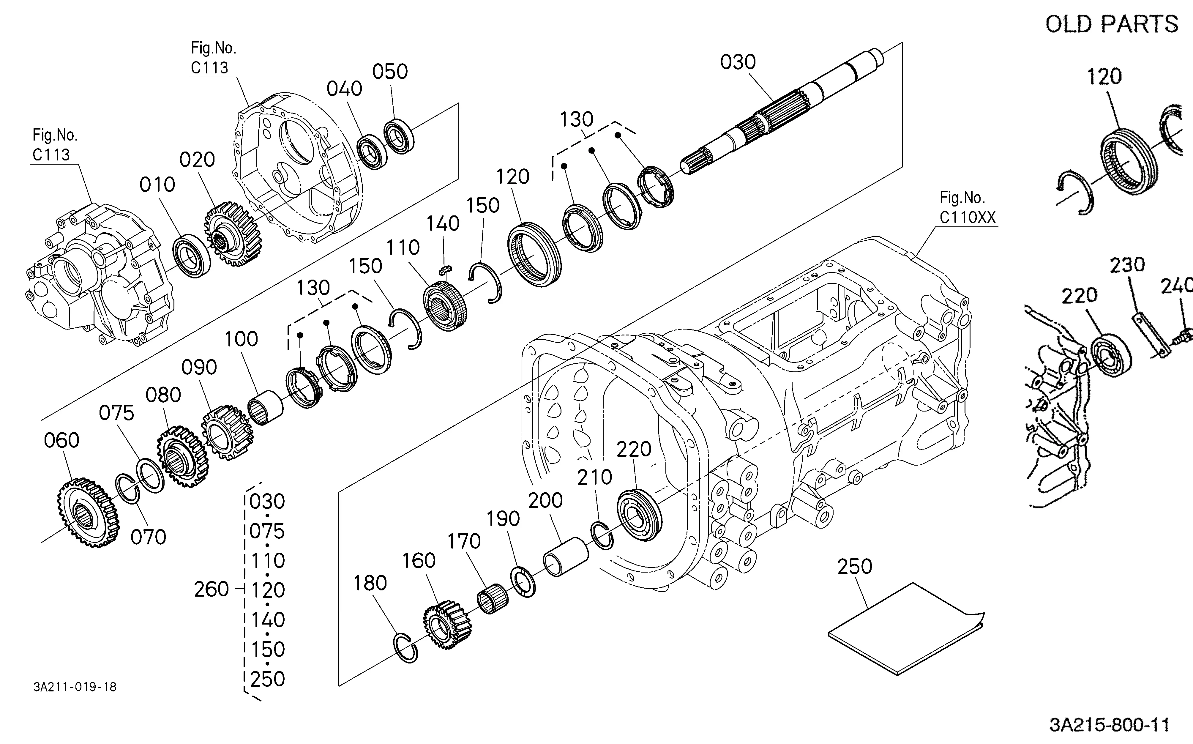
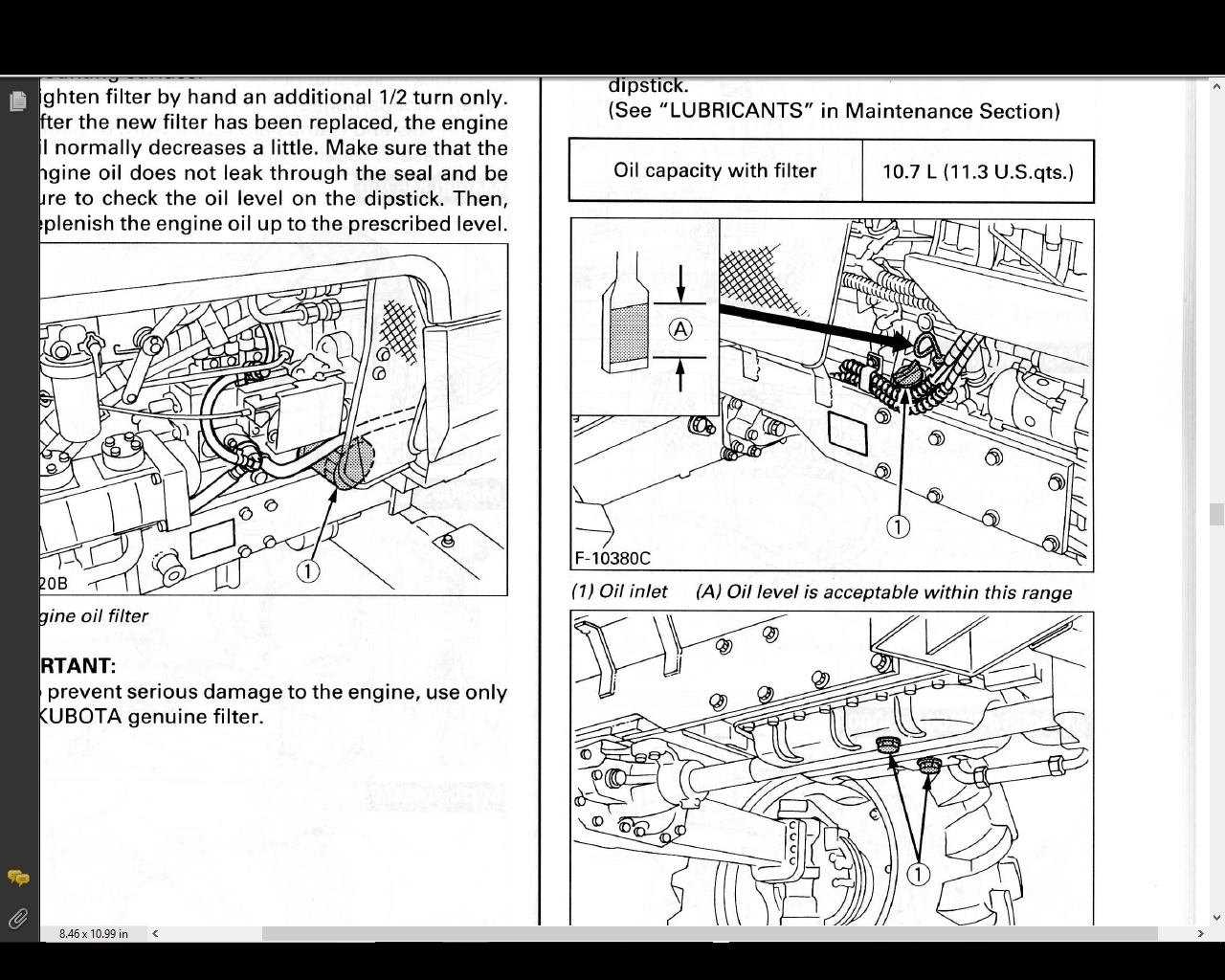
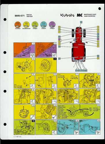
Kubota M4900 Parts Diagram and Breakdown
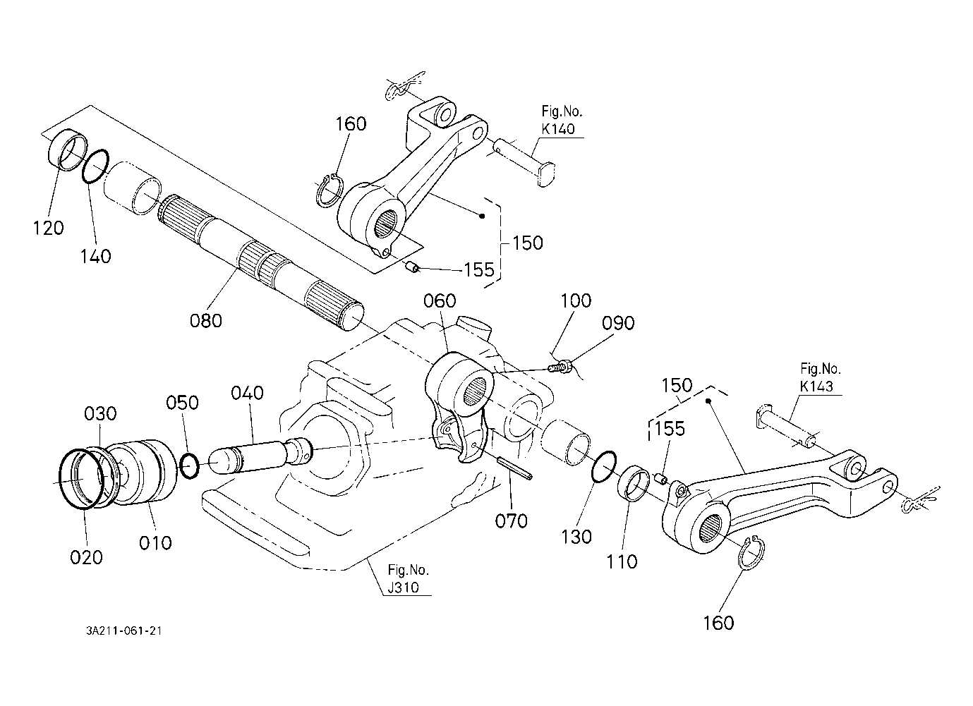
In the realm of agricultural equipment, comprehending the various elements that constitute a machine is essential for effective maintenance and operation. Each machine comprises numerous interconnected parts, each serving a specific function that contributes to overall performance. Recognizing these components aids in troubleshooting issues and ensuring optimal functionality.
The complexity of these machines often requires detailed visual representations to facilitate understanding. By examining illustrations or schematics that outline the arrangement and relationship of individual elements, operators can gain valuable insights into how their equipment operates. Such knowledge not only enhances repair efficiency but also empowers users to undertake preventive measures.
Moreover, familiarizing oneself with the key sections of machinery can lead to better decision-making regarding repairs and upgrades. Whether you are a seasoned technician or a novice, having access to clear and informative visuals can greatly enhance your expertise and confidence in handling various tasks associated with agricultural machinery.
Kubota M4900 Parts Diagram Overview

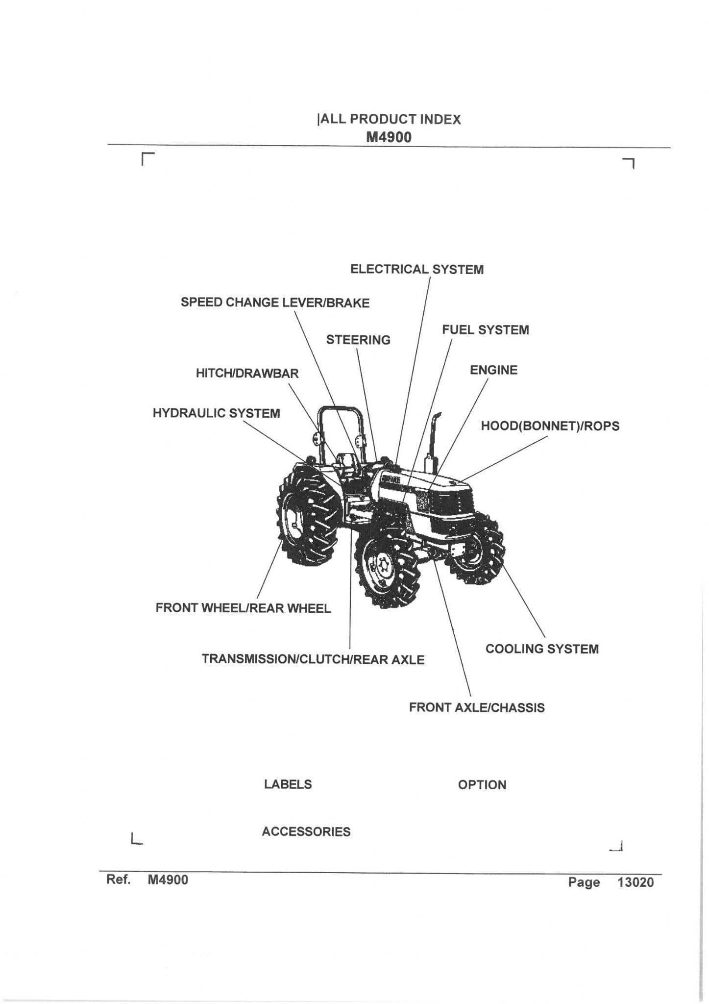
This section aims to provide a comprehensive overview of the components and their organization within the machinery, focusing on the essential elements that ensure optimal functionality. Understanding the layout and relationship between different parts is crucial for effective maintenance and repair procedures, allowing users to identify the necessary components quickly.
Key Components
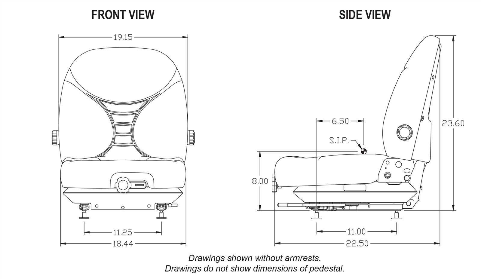
The following table highlights some of the primary elements associated with the machinery. This overview will assist users in recognizing the critical components for better management and servicing.
| Component Name | Description | Function |
|---|---|---|
| Engine Assembly | The main power source of the machine. | Converts fuel into mechanical energy. |
| Transmission Unit | Transfers power from the engine to the wheels. | Facilitates movement and speed control. |
| Hydraulic System | Consists of pumps, valves, and cylinders. | Enables lifting and operation of attachments. |
| Steering Mechanism | Controls the direction of the machine. | Ensures maneuverability. |
Conclusion
Familiarity with the layout and functionality of these components enhances the user’s ability to maintain and troubleshoot the equipment effectively. A well-organized understanding of the machinery’s structure significantly contributes to its longevity and performance.
Understanding the Importance of Diagrams
Visual representations play a crucial role in simplifying complex systems, enabling users to grasp the overall structure and functionality. By breaking down intricate mechanisms into smaller, easily understood components, these visuals help enhance clarity and improve comprehension.
Clarity and Simplification
One of the primary benefits of such visuals is their ability to simplify intricate details. Instead of overwhelming users with technical descriptions, a well-organized illustration can provide a clear view of how different elements are connected and operate in relation to one another.
- Helps visualize complex setups
- Enables quicker understanding of systems
- Supports troubleshooting by identifying key areas
Effective Communication Tool
In addition to offering clarity, these visual tools serve as an effective communication method. They bridge the gap between technical experts and those who may not have in-depth knowledge, ensuring information is conveyed accurately and efficiently.
- Breaks down barriers of technical jargon
- Facilitates quicker decision-making
- Improves collaboration between teams
Main Components of Kubota M4900
Understanding the key elements of the agricultural machine is essential for maintaining its operational efficiency. Each component plays a crucial role in ensuring the machine’s smooth performance, contributing to its longevity and productivity. The system relies on interconnected parts that must function harmoniously to deliver optimal results in various tasks.
Engine Assembly
The heart of the machine, the engine assembly, provides the necessary power for operation. Designed for heavy-duty tasks, this part delivers reliable performance, ensuring efficient fuel consumption and smooth operation. Regular maintenance of this section is critical for keeping the machinery running without interruptions.
Transmission System
The transmission system allows seamless control over speed and torque. It plays a vital role in adapting to different terrains and workloads, enabling smooth transitions between gears. Proper lubrication and adjustment of the transmission ensure consistent performance and extend the system’s lifespan.
How to Read Parts Diagrams
Understanding how to navigate schematics is essential for identifying various components and their relationships within a mechanical or technical system. These visual representations help users locate specific elements, comprehend their placement, and interpret how different parts connect and interact to ensure proper functionality.
Key Symbols and Notations
Technical drawings often include specific symbols and notations that represent different types of components, connectors, and fasteners. Learning to recognize these icons is important for accurately interpreting what is depicted. Below is a basic overview of common symbols and their meanings:
| Symbol | Meaning |
|---|---|
| Circle with a number | Identifies individual components or items |
| Dashed line | Indicates flexible connections or wiring |
| Solid line | Represents solid or rigid connections |
Step-by-Step Reading Guide
To efficiently read a schematic, follow these steps: first, identify the section or system you are examining. Next, locate numbered
Common Issues and Solutions
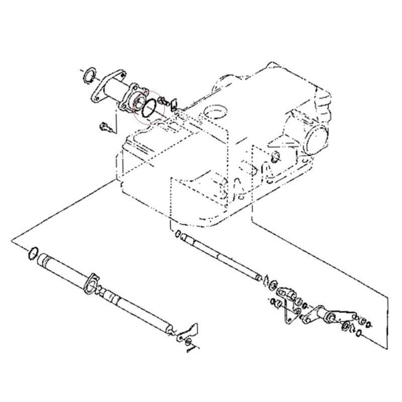
Machinery, especially when used extensively in demanding environments, can develop certain recurring problems over time. Identifying these issues early and applying the appropriate fixes can help maintain peak performance and extend the equipment’s operational lifespan. Below are some of the most frequent concerns and their corresponding resolutions.
Engine Performance Problems
Operators often encounter reduced engine power or irregular running. This can be caused by factors such as fuel system blockages, poor air intake, or ignition system issues. To resolve this, ensure the fuel filter is clean, check for air leaks in hoses, and verify that the ignition system components are functioning properly.
Hydraulic System Failures
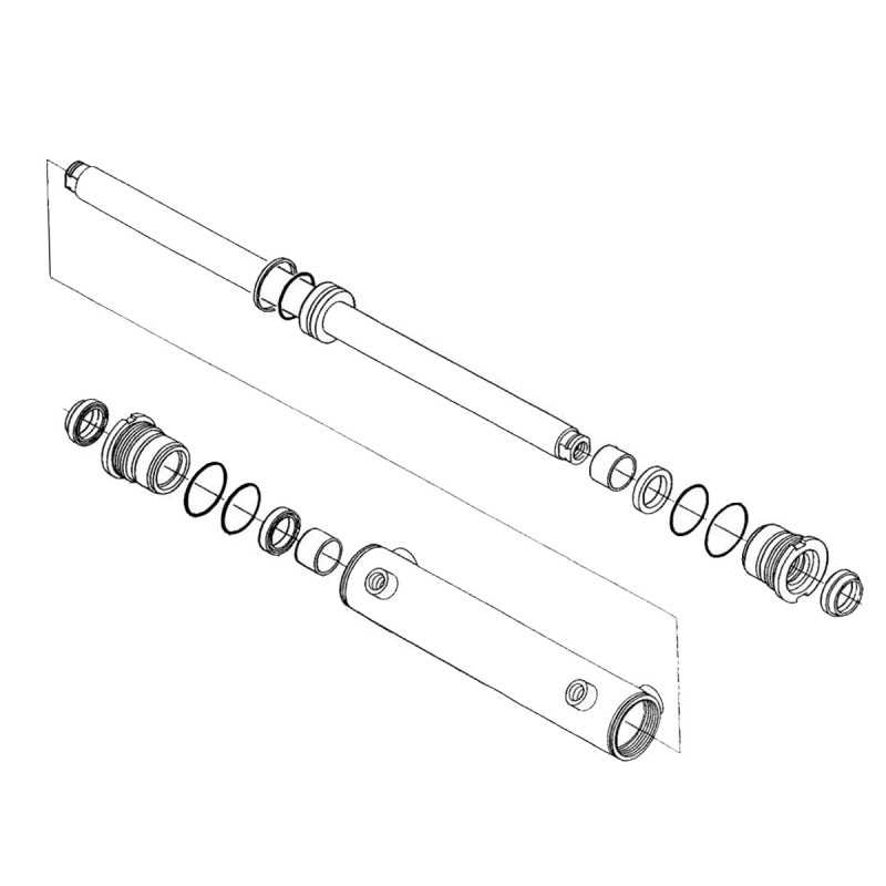
Hydraulic systems may experience reduced pressure, leaks, or complete failure. Regular maintenance, including checking fluid levels and inspecting hoses for wear or damage, can help prevent these problems. If the hydraulic system becomes unresponsive, replacing worn-out seals or checking the hydraulic pump may be necessary.
| Issue | Possible Cause |
Maintenance Tips for Kubota M4900Regular upkeep is essential to ensure the smooth operation and longevity of your agricultural equipment. By following a consistent maintenance schedule, you can prevent unexpected breakdowns and keep your machine running efficiently in the field. Oil and Fluid Checks: Always monitor engine oil levels and hydraulic fluids. Maintaining proper fluid levels ensures that critical components function properly and are less prone to damage. Filters: Replace air, fuel, and oil filters regularly to protect the engine from contaminants and debris. Clean filters allow for optimal performance and fuel efficiency. Inspect Belts and Hoses: Periodic inspection of belts and hoses helps to avoid wear-related issues. Cracks, leaks, or looseness should be addressed promptly to avoid costly repairs. Tire Pressure: Keep an eye on tire pressure to ensure balanced traction and minimize wear on tires. Proper inflation can improve both handling and fuel economy. Regular Lubrication: Lubricate moving parts such as joints, hinges, and bearings to reduce friction and prevent wear. This will prolong the life of essential components and ensure smoother operation. Identifying Parts by Diagram
Understanding how to recognize components using a schematic is crucial for efficient maintenance and repairs. Visual representations provide a clear view of how different elements are interconnected, making it easier to locate and understand individual parts.
By utilizing these visual tools, even intricate systems become more approachable, ensuring that the right elements are identified swiftly and correctly. Where to Find Replacement Parts
When it comes to maintaining your equipment, sourcing suitable components can sometimes be a challenge. Whether you need minor hardware or major mechanical elements, knowing where to look is crucial to ensuring smooth operation and durability. Authorized Dealers are often the most reliable sources for compatible replacements. They typically offer a range of items that meet the required specifications for your machine, ensuring quality and compatibility. Online platforms provide another convenient option for finding the necessary elements. Many websites offer a broad selection, often at competitive prices, and may provide the option to compare different manufacturers and models to find the best fit for your needs. Additionally, specialized retailers can be an excellent source of more specific parts. These stores often focus on particular categories, giving you access to expert knowledge and tailored solutions for your equipment. Comparing Different Models and DiagramsWhen analyzing various equipment configurations, it’s essential to understand how their components interact and function as a whole. Each model, while designed for similar purposes, may have different structural elements, leading to variations in the layout and arrangement of its internal systems. Identifying these differences can aid in effective maintenance, repair, and upgrades. Key Variations Between ModelsModels designed for similar tasks may differ in terms of engine design, transmission, or hydraulic systems. These distinctions are often reflected in their visual representations, where specific layouts highlight how unique parts are positioned or connected differently across models. Understanding Diagram DifferencesDiagrams offer crucial insights into the placement of major components and subsystems. By comparing visual aids across models, you can quickly identify upgrades, alternative setups, or improvements in design that impact the performance and usability of the equipment. Benefits of Using Genuine PartsChoosing authentic components for your machinery ensures reliability, performance, and longevity. These elements are specifically designed to fit and function seamlessly, providing better results over time. By opting for original replacements, you protect your equipment from potential damage and costly repairs.
Frequently Asked Questions About DiagramsMany individuals encounter questions when exploring visual representations of mechanical systems. Understanding how to read and interpret these layouts can often raise various concerns, especially for those unfamiliar with technical drawings. In this section, we address some of the most common inquiries related to these visual tools. How Do You Read Technical Diagrams?Technical diagrams are designed to simplify complex systems, breaking them down into easy-to-understand parts. To effectively interpret them, it’s important to focus on key components and their relationships. Symbols, lines, and labels typically provide the necessary guidance to help you navigate through the layout. Why Are These Visual Tools Important?
These illustrations offer a structured way to visualize how different components work together. By examining these detailed images, users can gain insights into assembly procedures, system functionality, and potential troubleshooting solutions. |
|---|
