Kubota T1870 Component Layout Guide
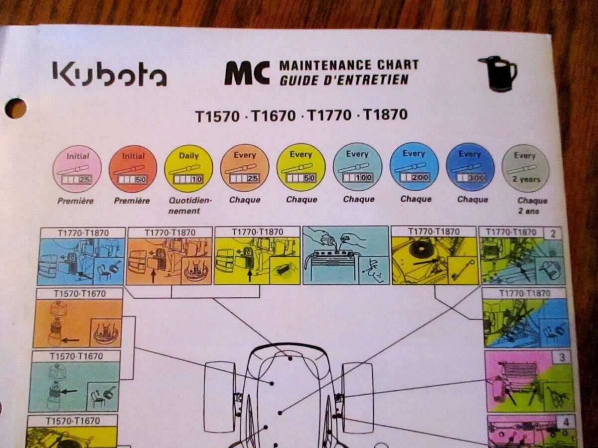
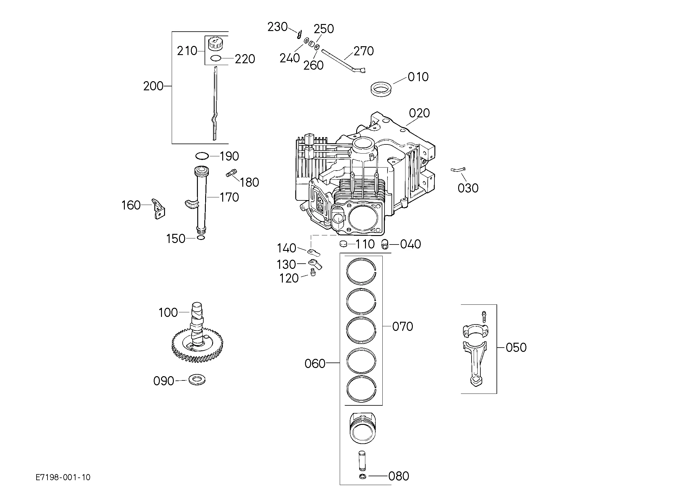
When dealing with mechanical equipment, a clear understanding of how each element fits together is essential. Knowing the layout of various components helps to streamline maintenance and ensures that any replacements or upgrades are done correctly. This knowledge not only saves time but also improves the overall performance of the machinery.
Examining the arrangement of individual elements allows for efficient troubleshooting and diagnostics. By identifying the precise position and function of each unit, users can quickly address any issues that may arise during operation. A well-organized reference guide serves as a valuable tool for both novices and experienced technicians.
Detailed information on structural assembly is vital for anyone looking to enhance their technical skills. It provides a foundation for deeper exploration into the mechanics of the system, offering insights into how different parts work in harmony to deliver optimal functionality. This comprehensive approach empowers users to maximize the longevity and reliability of their equipment.
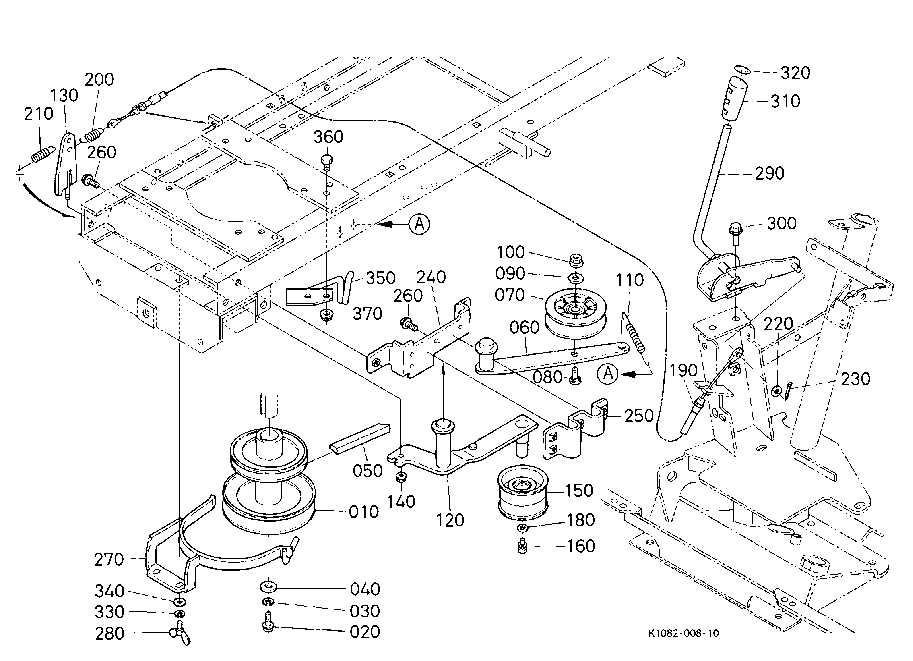
The transmission assembly is a crucial component in any mechanical system, responsible for directing power from the engine to the wheels. A well-functioning assembly ensures smooth and efficient operation, enabling the machine to adapt to various terrains and workloads with ease.
Key Components of the Transmission
- Gearbox: This element is vital for managing speed and torque. It allows for the adjustment of the vehicle’s pace while maintaining optimal engine performance.
- Clutch Mechanism: Acts as the connection point between the engine and the transmission. It plays a key role in engaging and disengaging the drive power smoothly.
- Drive Shaft: Transfers the torque generated by the engine to the wheels, enabling motion. It needs to be sturdy and precisely aligned for effective operation.
Maintenance Tips for Longevity
- Regular Lubrication: Ensuring all moving parts are adequately lubricated can prevent friction and reduce wear and tear on the system.
- Periodic Inspection: Routine checks can help identify any signs of damage or unusual noise, allowing for timely repairs before issues escalate.
- Component Alignment: Proper alignment of the assembly parts is essential to prevent vibrations and maintain a smooth power transfer process.
Maintaining the transmission assembly in prime condition not only extends the lifespan of the machinery but also optimizes its performance across different tasks and conditions.
Exploring the Mower Deck Structure
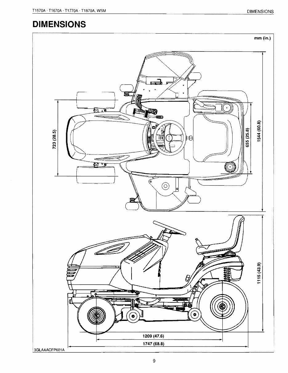
The foundation of any cutting machine’s efficiency lies in its base assembly. Understanding the design of this section is essential for maintaining optimal performance and ensuring a clean, precise trim. Let’s break down the key components that make up this area.
- Main Frame: This element provides support and stability, holding all other components together securely.
- Blades Assembly: The sharp, rotating edges that execute the actual cutting task, their alignment and condition greatly impact the final result.
- Belt System: Responsible for transferring power from the engine to the blades, this setup ensures smooth and consistent operation.
- Height Adjusters: These allow for precise control over the cutting height, giving flexibility to handle different grass lengths.
- Protective Guards: Shields and covers that ensure safe usage, preventing debris from being ejected during the process.
By examining these core parts, it’s easier to understand how the lower assembly functions as a cohesive unit, delivering a reliable and even trim across any terrain.
Analyzing the Electrical Wiring Layout
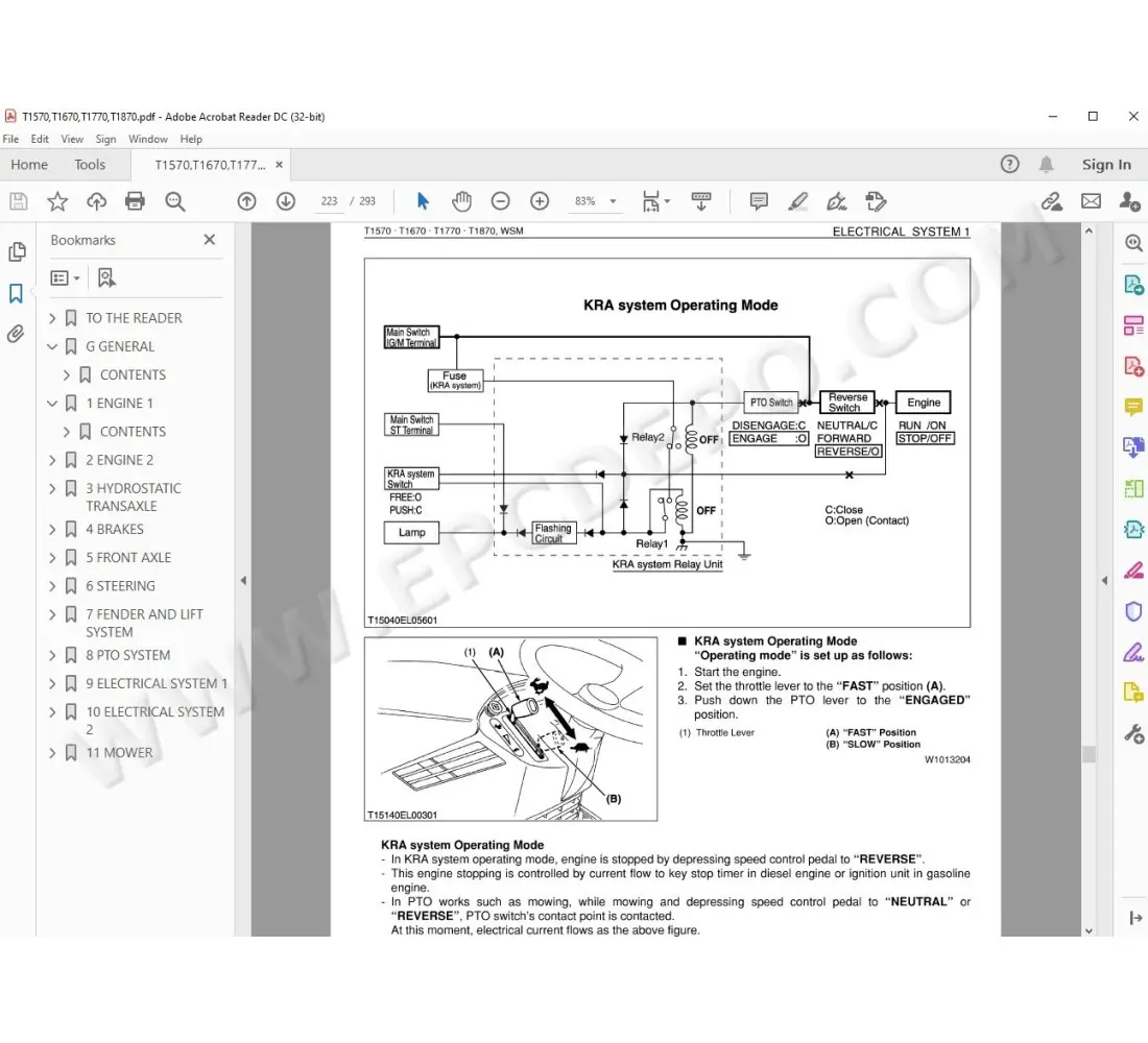
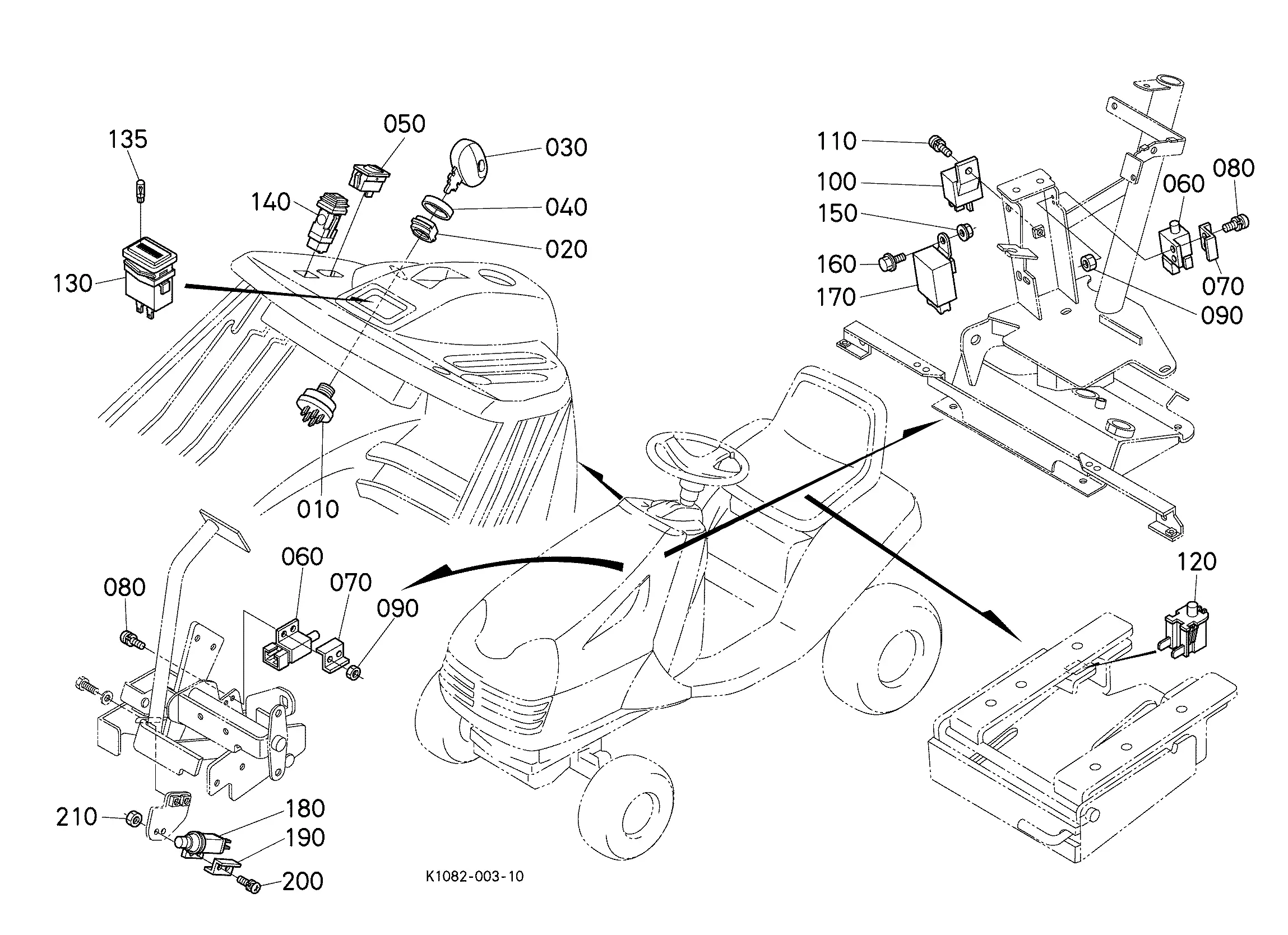
The electrical connections within a mechanical system serve as the backbone for its functionality, ensuring that each component operates seamlessly. Understanding the configuration of these connections is crucial for maintenance and troubleshooting, as it helps to identify potential issues quickly.
| Component | Connection Type | Functionality |
|---|---|---|
| Ignition Module | Direct Wire | Initiates the power sequence for engine startup |
| Lighting System | Circuit Loop | Provides illumination during operation |
| Control Switches | Relay-Based | Manages various functions of the machinery |
Breaking down these connections into manageable sections allows for a detailed analysis, making it easier to perform repairs or enhancements. Proper evaluation of the wiring structure helps ensure safety and optimal performance of the system.
Fuel System Components and Connections
The fuel delivery setup plays a crucial role in ensuring the smooth operation of any engine, managing how the energy source moves from the tank to the motor. Each component and its linkage within this system must function in harmony to deliver consistent performance. In this section, we’ll explore the individual elements of the setup and how they interact.
Main Elements of the Fuel Delivery Setup
The key elements in this arrangement typically include the pump, injectors, lines, and filter. The pump is responsible for propelling the liquid through the system, while the injectors precisely distribute it into the engine. Tubing and hoses ensure that the fluid flows seamlessly between components, while the filter keeps impurities from entering the sensitive areas.
Connection Points and Pathways
Understanding the connection points within the fuel setup is essential for maintenance and troubleshooting. These points often include joints, clamps, and seals that secure the lines and hoses. Regular inspection of these connections can help prevent leaks and ensure that the flow remains uninterrupted.
| Component | Function | Common Issues | |||||||||
|---|---|---|---|---|---|---|---|---|---|---|---|
| Fuel Pump | Moves the liquid to the engine | Loss of pressure, noise | |||||||||
| Injectors | Spray fuel into the
Detailed View of Steering Mechanism
The steering system is a crucial component that facilitates precise maneuvering and control of the vehicle. Its design ensures smooth operation, allowing the operator to navigate various terrains effectively. A comprehensive understanding of its structure can help in identifying potential issues and enhancing performance. Key Components of the Steering AssemblyThe steering assembly consists of several integral parts, each playing a significant role in functionality. Steering wheel serves as the primary control interface, transmitting the operator’s inputs through a series of linkages. The steering column connects the wheel to the mechanism, while the rack and pinion system converts rotational motion into linear movement, guiding the wheels. Importance of Maintenance
Regular maintenance of the steering assembly is vital to ensure optimal performance and safety. Lubrication of moving parts reduces friction and wear, while inspections for any signs of damage or misalignment can prevent more serious issues. Keeping these components in good condition will enhance responsiveness and longevity of the system. Brake and Clutch System Analysis
This section delves into the intricacies of the braking and clutch mechanisms, focusing on their functional roles in ensuring smooth operation and safety. A thorough examination reveals how these components work together to provide the necessary control and responsiveness in various operating conditions. Functionality OverviewThe braking system is essential for deceleration and stopping, relying on friction to reduce speed. This process is complemented by the clutch mechanism, which facilitates smooth gear transitions, allowing for effective power transfer between the engine and the drivetrain. Understanding the interplay between these systems is crucial for optimal performance and reliability. Common Issues and Maintenance
Regular maintenance is vital for both systems to prevent common issues such as wear and tear, fluid leaks, and improper adjustments. Identifying symptoms of malfunction early can enhance longevity and efficiency. Ensuring proper lubrication and timely replacement of worn components are key practices for maintaining peak performance. Hydraulic System Breakdown
The hydraulic mechanism of a vehicle plays a crucial role in ensuring optimal functionality and performance. Understanding its components and their interrelations is essential for effective maintenance and troubleshooting. This section will delve into the various elements that constitute the hydraulic setup, emphasizing their significance in the overall operation. Key Components
At the heart of the hydraulic system are several vital elements, including pumps, cylinders, and hoses. Each component contributes to the efficient transmission of fluid, which facilitates movement and power transfer throughout the machine. Regular inspection of these parts is necessary to prevent malfunctions and ensure longevity. Common Issues and SolutionsUsers may encounter various challenges, such as leaks, pressure loss, or sluggish operation. Identifying the source of these issues is critical. For instance, worn seals or damaged hoses can lead to fluid leakage, while inadequate fluid levels may cause pressure drops. Addressing these concerns promptly can help maintain the system’s performance. Cooling System Parts Identification
The efficiency of any machine’s cooling mechanism is crucial for its optimal performance. Understanding the components involved in this system is essential for maintaining proper functionality and preventing overheating. This section delves into the various elements of the cooling assembly, providing insights for accurate identification and troubleshooting. Key Components
Identification Tips
Understanding Chassis Frame Layout
The chassis frame serves as the foundational structure for any vehicle, providing support and stability. This layout is crucial as it influences the overall performance, handling, and durability of the machine. A well-designed frame is essential for accommodating various components while ensuring optimal weight distribution and strength. When examining the configuration of the chassis, several key aspects must be considered. These include the frame type, materials used, and structural integrity. Different designs can offer advantages in terms of resilience and ease of maintenance.
Understanding the layout of the chassis frame is vital for anyone involved in the operation or maintenance of vehicles. It not only determines the vehicle’s performance but also plays a significant role in ensuring safety and reliability during operation. Exhaust System Components GuideThe exhaust system plays a crucial role in the overall performance of a machinery unit, ensuring efficient expulsion of combustion gases while minimizing noise and emissions. Understanding the various components within this system can aid in maintenance and troubleshooting, leading to enhanced functionality and longevity of the equipment. Here is a breakdown of key elements typically found in exhaust systems:
Regular inspection of these components is essential to ensure optimal performance. Identifying any signs of wear or damage can help prevent larger issues down the line. To maintain the exhaust system effectively, consider the following maintenance tips:
By paying attention to these components and following maintenance recommendations, operators can ensure their machinery runs smoothly and efficiently. |
