Comprehensive Guide to 4090hk17 Parts Diagram

In the world of advanced machinery, comprehending the layout and arrangement of various elements is crucial for effective operation and maintenance. This knowledge not only aids in troubleshooting but also enhances the overall efficiency of the system. A clear representation of how each component interacts with others can provide invaluable insights for technicians and enthusiasts alike.
Exploring the configuration of intricate systems allows for a deeper appreciation of their functionality. Each unit plays a specific role, contributing to the harmonious operation of the whole. Recognizing the significance of each section and how they fit together empowers users to make informed decisions regarding upgrades, repairs, and enhancements.
By examining these configurations, one can identify potential issues and devise effective solutions. This exploration fosters a proactive approach to maintenance, ensuring that the machinery operates smoothly and reliably. A detailed overview serves as a roadmap, guiding users through the complexities of their systems with clarity and precision.
Key Components of the 4090hk17
This section delves into the essential elements that contribute to the functionality and efficiency of the system. Understanding these components is crucial for anyone looking to enhance their knowledge or performance of the equipment. Each element plays a significant role in ensuring the overall operation runs smoothly and reliably.
Core Processor: The central processing unit (CPU) is the heart of the setup, responsible for executing instructions and managing tasks. Its speed and architecture directly impact the system’s performance.
Memory Units: These storage devices provide the necessary space for data and applications, allowing quick access and retrieval. The capacity and speed of these units can significantly influence the efficiency of operations.
Power Supply: This component converts electrical power from an outlet into usable power for the internal components. A stable and efficient power supply ensures that all parts function optimally without interruptions.
Cooling Systems: Effective thermal management is vital for maintaining the performance and longevity of the internal elements. These systems dissipate heat generated during operation, preventing overheating and potential damage.
Input/Output Interfaces: These connections facilitate communication between the device and external peripherals. Their design and compatibility are crucial for seamless integration with other equipment.
Understanding these core components is fundamental for troubleshooting, maintenance, and performance optimization of the entire system.
Functionality of Major Parts
This section explores the essential roles played by key components within the system. Each element contributes significantly to the overall performance and efficiency, ensuring smooth operation and functionality. Understanding these functionalities allows for better insights into the entire mechanism.
Core Components
The central elements are designed to work in harmony, facilitating various processes. They are responsible for generating power, managing resources, and ensuring stability during operation. Their interdependence is critical for optimal performance.
Auxiliary Elements
Supporting features enhance the system’s efficiency and reliability. They assist in regulating temperatures, providing connectivity, and enabling user interaction. These components often include sensors, regulators, and interfaces, each serving a unique purpose that complements the core functions.
| Component | Functionality |
|---|---|
| Generator | Produces the necessary energy for operation. |
| Regulator | Maintains optimal performance levels by managing resource distribution. |
| Sensor | Monitors conditions and provides feedback for adjustments. |
| Interface | Facilitates user interaction and system control. |
Common Issues and Solutions
In any complex system, encountering challenges is a routine aspect of operation. Understanding these common hurdles and their corresponding resolutions is essential for maintaining optimal functionality. This section outlines frequent problems users may face, along with practical solutions to address them effectively.
Typical Problems
Various difficulties can arise, affecting performance and usability. Issues may include connectivity problems, improper configurations, and component failures. Identifying these issues quickly can save time and prevent further complications.
Recommended Solutions
| Issue | Solution |
|---|---|
| Connectivity Issues | Check all connections and ensure that cables are securely attached. Restart the device to reset the connection. |
| Configuration Errors | Review settings and adjust them according to the user manual. Factory reset may be necessary in some cases. |
| Component Malfunction | Inspect for visible damage. Replace any faulty parts or seek professional assistance for repairs. |
Maintenance Tips for Longevity
Ensuring the long-lasting performance of any machinery requires diligent upkeep and attention to detail. By following a series of maintenance practices, one can significantly extend the lifespan of essential components while enhancing overall functionality. Regular checks and timely interventions play a crucial role in avoiding costly repairs and downtime.
Regular Inspections

Routine assessments are vital in identifying potential issues before they escalate. Check for wear and tear, loose connections, or signs of corrosion. Implementing a schedule for these inspections can help in early detection and prevent unforeseen breakdowns. Paying attention to detail during these evaluations can lead to better decision-making regarding necessary repairs or replacements.
Proper Cleaning and Lubrication
Keeping the machinery clean is essential for optimal operation. Dust, dirt, and debris can impede performance and lead to malfunctions. Regularly clean surfaces and components to maintain efficiency. Additionally, proper lubrication is crucial in minimizing friction and wear. Using the right type of lubricant at appropriate intervals will ensure smooth operation and reduce the risk of overheating.
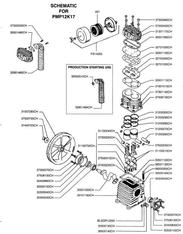
How to Read the Parts Diagram

Understanding a schematic representation of components is essential for effective troubleshooting and assembly. This section will guide you through the key elements of such visual guides, helping you navigate and interpret the information they provide.
Key Elements to Look For
- Labels: Each element typically has a corresponding label that indicates its name or function. Familiarize yourself with these to quickly identify parts.
- Numbers: Numerical annotations often denote quantities or specific order sequences, aiding in the assembly process.
- Connections: Look for lines or arrows indicating how components are linked. This is crucial for understanding flow and interaction.
- Shapes: Different shapes represent various types of components, making it easier to differentiate between them at a glance.
Tips for Effective Interpretation

- Familiarize yourself with the legend or key, which often provides essential information on symbols used.
- Take your time to cross-reference labels with descriptions to ensure accurate identification.
- Practice makes perfect; the more you analyze these visual guides, the more intuitive they will become.
- Consult additional resources or manuals if you encounter unfamiliar symbols or components.
Replacement Parts Overview
This section provides essential information about various components that may require substitution over time. Understanding the individual elements of a system is crucial for maintenance and optimal performance. Having a reliable resource for identifying necessary replacements can enhance efficiency and prolong the lifespan of the unit.
Commonly Replaced Components
- Cooling Unit: Ensures optimal temperature regulation.
- Power Module: Vital for energy supply and regulation.
- Control Board: Central to system operations and functionalities.
- Display Screen: Provides user interface for monitoring and control.
Tips for Selecting Components
- Ensure Compatibility: Verify that the replacement aligns with existing specifications.
- Quality Assurance: Opt for certified components from reputable manufacturers.
- Check Reviews: Assess feedback from other users to gauge performance and reliability.
- Consult Documentation: Refer to the manufacturer’s guidelines for recommended substitutions.
Installation Process of Components
The installation of various elements is a critical procedure that ensures the proper functionality of the system. Each component plays a significant role in the overall performance and reliability of the device. This section outlines the essential steps involved in successfully integrating these elements, focusing on best practices and common considerations during the process.
To facilitate the installation, it is important to have a clear understanding of the components involved, as well as the tools required. Below is a brief overview of the typical steps to follow:
| Step | Description |
|---|---|
| 1 | Gather all necessary tools and components to ensure a smooth installation process. |
| 2 | Carefully review the installation instructions for each element to avoid any errors. |
| 3 | Begin with the primary unit, ensuring a secure and stable foundation before adding additional components. |
| 4 | Connect each element according to the specified guidelines, paying close attention to compatibility. |
| 5 | After installation, conduct a thorough inspection to confirm that all components are correctly positioned and secured. |
| 6 | Finally, power on the system and monitor its performance to ensure everything operates as intended. |
Safety Precautions During Handling
Ensuring safety while managing components is crucial to prevent accidents and maintain operational efficiency. Proper precautions can mitigate risks associated with handling delicate materials, ensuring a safe working environment.
General Guidelines
- Always wear appropriate personal protective equipment (PPE), such as gloves and safety goggles.
- Ensure that the workspace is clean and free from hazards that could lead to slips or falls.
- Keep tools and equipment organized to avoid accidents caused by clutter.
- Use proper lifting techniques to prevent injuries; lift with your legs, not your back.
Specific Considerations
- Verify that all components are stored in a secure location to avoid accidental damage.
- Handle items with care, avoiding excessive force that could lead to breakage.
- Follow manufacturer instructions regarding the handling and storage of sensitive items.
- In case of spills or leaks, follow the established protocols to address them promptly.
Differences with Similar Models
When comparing various devices within the same category, it is essential to understand the unique features and specifications that distinguish one model from another. This understanding not only aids consumers in making informed purchasing decisions but also highlights advancements in technology and design that may cater to specific needs or preferences.
Key Specifications Comparison
Different models may vary in terms of performance, design, and additional functionalities. The following table outlines some of the significant differences that may impact user experience:
| Feature | Model A | Model B | Model C |
|---|---|---|---|
| Processing Speed | 2.5 GHz | 3.0 GHz | 2.8 GHz |
| Memory Capacity | 16 GB | 32 GB | 16 GB |
| Storage Type | SSD | HDD | SSD |
| Display Size | 15.6 inches | 17.3 inches | 15.6 inches |
Target Audience and Use Cases
Each model is designed with specific users in mind. While some may cater to gamers seeking high performance, others might target professionals needing reliable and efficient tools for everyday tasks. Understanding these distinctions can help potential buyers choose a model that aligns with their requirements and usage patterns.
Tools Needed for Repair
Effective maintenance and troubleshooting require a selection of essential implements. Having the right equipment not only enhances the efficiency of the repair process but also ensures that tasks are executed safely and accurately. Below is an overview of the necessary tools that should be part of every technician’s toolkit.
Essential Hand Tools
Hand tools are fundamental for any repair job. These tools allow for precise adjustments and assembly without causing damage to the components.
| Tool | Description |
|---|---|
| Screwdriver Set | A variety of screwdrivers, including flathead and Phillips, for fastening and unfastening screws. |
| Pliers | Used for gripping, bending, and cutting wire or small parts. |
| Socket Wrench | A versatile tool for tightening or loosening nuts and bolts. |
Specialized Equipment
In addition to hand tools, certain specialized equipment is required for more complex repairs. These tools help address specific issues effectively.
| Tool | Description |
|---|---|
| Multimeter | A device for measuring voltage, current, and resistance, essential for electrical diagnostics. |
| Soldering Iron | Used for soldering connections and repairing circuit boards. |
| Heat Gun | Useful for heat-shrinking tubing or removing adhesive components. |
Frequently Asked Questions
This section addresses common inquiries related to components and their arrangements, providing clarity on various aspects that users often seek to understand.
General Inquiries
- What is the purpose of the different elements within the system?
- How can I identify a malfunctioning unit among the various components?
- Are there any recommended maintenance practices to ensure longevity?
Technical Support
- Where can I find replacement units if needed?
- Is there a specific tool required for installation or removal?
- What are the most common troubleshooting steps for performance issues?