Understanding the BCS Parts Diagram for Optimal Maintenance

In the realm of machinery and engineering, the intricate interplay of various elements plays a crucial role in ensuring optimal functionality and performance. Each component, while seemingly independent, contributes to the overall efficiency of the system, often working in harmony with others to achieve desired outcomes. Grasping the relationship between these elements is essential for anyone involved in maintenance, repair, or design.
Comprehending the layout and arrangement of these crucial elements can significantly enhance troubleshooting and operational strategies. By visualizing how each piece fits within the larger assembly, one gains insights into potential issues and can better predict the impacts of modifications or repairs. This knowledge is invaluable for engineers and technicians alike, empowering them to make informed decisions.
Moreover, the ability to interpret these configurations fosters a deeper understanding of the underlying principles of operation. It not only aids in identifying wear and tear but also facilitates efficient upgrades and replacements. Embracing this knowledge opens doors to improved practices and innovative solutions within the field, ultimately leading to enhanced reliability and performance.
Understanding BCS Parts Diagrams
Grasping the intricacies of technical schematics is essential for effective maintenance and troubleshooting. These visual representations serve as vital tools, facilitating a comprehensive understanding of complex systems. By breaking down components and their relationships, users can navigate the assembly with greater ease.
Key Components of the Schematics
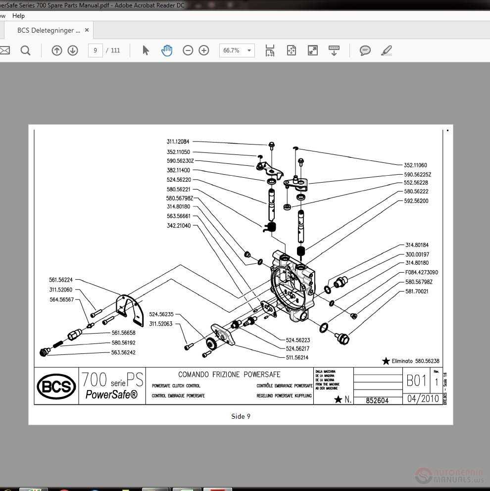
- Symbols: Each symbol denotes a specific element, making identification straightforward.
- Connections: Lines illustrate how various elements interact, providing insight into functionality.
- Labels: Clear annotations help in understanding the purpose and specifications of each part.
Benefits of Utilizing Visual Representations
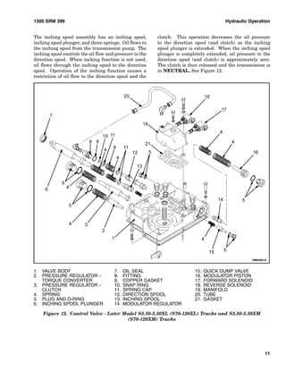
- Enhanced Clarity: Simplifies complex information into digestible formats.
- Improved Communication: Facilitates better dialogue among technicians and engineers.
- Efficient Problem-Solving: Aids in pinpointing issues swiftly by visualizing the system layout.
Importance of BCS Diagrams in Maintenance
Effective maintenance is crucial for the longevity and efficiency of any complex system. Visual representations of components and their interrelations play a significant role in ensuring that maintenance personnel can quickly understand and address issues that arise. These illustrations serve as valuable references that facilitate clearer communication, reduce downtime, and enhance overall operational efficiency.
Understanding the layout and function of system elements allows technicians to identify potential problems more swiftly. By having a detailed overview of how parts interact, maintenance teams can troubleshoot effectively, leading to timely interventions. This not only minimizes disruptions but also contributes to safer working environments.
| Benefits of Visual Representations | Description |
|---|---|
| Enhanced Clarity | Visual aids provide clear insights into the structure and function of components. |
| Improved Communication | Facilitates better discussions among team members and between departments. |
| Faster Problem Resolution | Helps in quickly diagnosing issues by providing a holistic view of the system. |
| Training Resource | Serves as an educational tool for new technicians to understand system intricacies. |
Incorporating these visual tools into maintenance practices not only streamlines processes but also fosters a proactive approach to system upkeep. By prioritizing such resources, organizations can significantly enhance their operational reliability and performance.
Key Components of BCS Systems
Understanding the essential elements of a control system is crucial for its effective implementation and operation. Each component plays a vital role in ensuring seamless functionality, contributing to the overall efficiency and reliability of the system. The integration of these parts allows for optimal performance and enhances the ability to monitor and manage various processes.
One of the fundamental elements is the sensor, which captures data from the environment and transmits it for processing. This information is crucial for making informed decisions and adjustments within the system. Additionally, actuators serve as the interface between the control signals and the physical environment, enabling the necessary responses to maintain desired conditions.
The controller is another pivotal component, interpreting the data received from the sensors and issuing commands to the actuators. Its algorithms are designed to optimize performance based on predefined criteria, ensuring that the system operates within specified parameters. Furthermore, communication networks facilitate the exchange of information among all components, allowing for real-time monitoring and adjustments.
Lastly, the user interface provides operators with the tools necessary to interact with the system, offering visualizations and controls that enhance usability. Together, these elements create a cohesive structure that maximizes efficiency and ensures reliability in various applications.
How to Read BCS Diagrams

Understanding complex visual representations can greatly enhance your ability to grasp intricate systems. These illustrations serve as vital tools for identifying components and their interconnections. By breaking down the elements within these visuals, you can gain insights into their functionality and relationships.
Step 1: Begin by familiarizing yourself with the legend or key, as it provides essential information about symbols and notations used in the illustration. Each icon represents a specific element, and knowing this will enable you to interpret the content accurately.
Step 2: Next, identify the main sections of the visual. Typically, components are organized in a logical flow, helping you trace their interactions. Pay attention to arrows or lines, as they indicate relationships and processes, guiding you through the overall function.
Step 3: Lastly, take your time to delve deeper into individual elements. Examining each part closely allows for a better understanding of its role and importance within the broader system. This thorough approach leads to a more complete comprehension of the entire framework.
Common Issues Identified in Diagrams
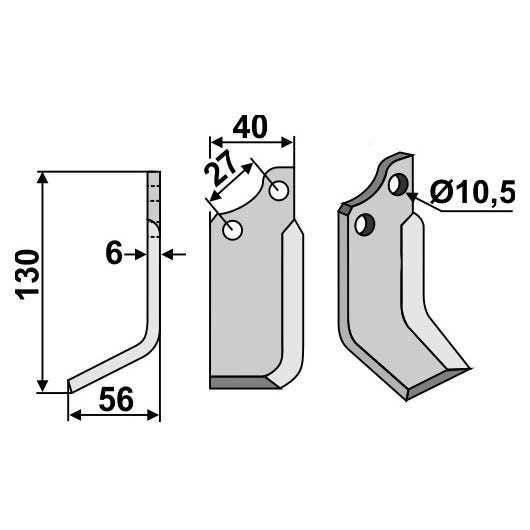
Visual representations often present challenges that can lead to misunderstandings or errors in interpretation. Identifying these issues is crucial for effective communication and accurate analysis. Mislabeling, unclear connections, and omitted components frequently create confusion, impacting overall functionality.
One prevalent problem is the inconsistency in labeling, which can mislead users about the roles of various elements. Additionally, unclear or incomplete linkages between components may result in misinterpretations of how systems interact, hindering troubleshooting efforts. It’s also common for essential parts to be excluded, leading to a skewed understanding of the overall structure.
Regular reviews and updates of visual aids can mitigate these issues, ensuring clarity and reliability in technical communication. By addressing common pitfalls, users can enhance their comprehension and operational efficiency.
Benefits of Accurate Diagram Usage
Utilizing precise visual representations in technical contexts offers numerous advantages. These graphical tools serve as essential aids in understanding complex systems and components, facilitating clearer communication among team members and enhancing overall productivity.
Enhanced Communication

Clear illustrations bridge the gap between technical jargon and practical understanding. They enable individuals, regardless of their expertise, to grasp intricate concepts quickly. This fosters collaboration, as everyone can engage with the content effectively, leading to informed decision-making.
Improved Efficiency
When accurate visuals are employed, the risk of misinterpretation diminishes significantly. This precision reduces the time spent on troubleshooting and clarifies processes, allowing teams to focus on their tasks with confidence. As a result, workflows become more streamlined and productive.
In summary, effective use of visual aids enhances both communication and efficiency, ultimately contributing to successful project outcomes.
Steps to Create BCS Parts Diagram
Crafting a visual representation of components requires a systematic approach to ensure clarity and accuracy. This process involves several essential stages, from initial planning to the final touches that enhance understanding. Below are the steps that will guide you through creating an effective illustration of your components.
1. Define Objectives
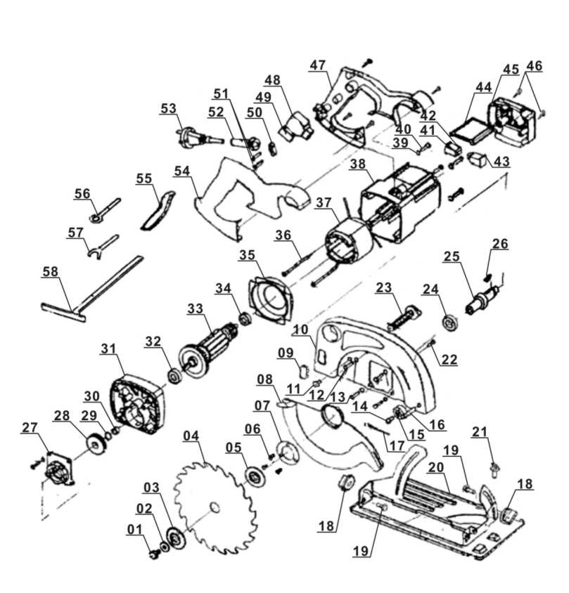
Begin by identifying the purpose of your visual. Consider the audience and what information is crucial for them. Establishing clear objectives will help you decide which elements to include and how to arrange them for optimal comprehension.
2. Gather Necessary Information
Collect all relevant data regarding the components you wish to illustrate. This may include specifications, dimensions, and any interconnections among elements. Having comprehensive information will enable you to create a more detailed and informative representation.
Remember: Accuracy is vital, as any discrepancies can lead to confusion or misinterpretation.
3. Sketch a Layout

Create a rough sketch of your illustration. This step allows you to visualize the arrangement of elements and how they relate to each other. Focus on the flow and ensure that the layout supports the objectives defined earlier.
4. Choose the Right Tools
Select software or tools that will aid in transforming your sketch into a polished visual. Many applications offer templates and features specifically designed for component illustrations, enhancing both ease of use and aesthetics.
Final Touches: After creating the visual, review it for clarity and coherence. Make adjustments as necessary to ensure that it effectively communicates the intended message.
Software Tools for Diagram Creation
In the realm of visual representation, utilizing specialized applications can significantly enhance clarity and understanding. These digital platforms provide users with the ability to construct intricate visuals that convey complex information effectively.
Key applications in this field offer a variety of features, including customizable templates, drag-and-drop functionality, and collaborative tools. This versatility allows for the seamless integration of various elements, making the creative process both intuitive and efficient.
Furthermore, many of these tools support cloud-based solutions, enabling users to access their projects from anywhere and collaborate in real-time with team members. This accessibility fosters innovation and improves communication among stakeholders.
Ultimately, choosing the right software can make a profound difference in how ideas are visualized and shared, streamlining workflows and enhancing productivity.
Interpreting Symbols in BCS Diagrams

Understanding the visual language used in technical schematics is crucial for effective communication in engineering and design. Each symbol represents specific components and functions, allowing for a concise and universally comprehensible representation of complex systems. Mastering these symbols can significantly enhance one’s ability to analyze and troubleshoot various mechanisms.
Symbols serve as a shorthand, encapsulating detailed information about the elements they depict. For instance, shapes like rectangles, circles, and triangles often signify different types of devices or processes. Familiarity with these forms enables users to quickly grasp the relationships between various parts of a system.
Furthermore, lines and arrows within these illustrations convey essential details about connections and flow. Solid lines typically indicate physical connections, while dashed lines may suggest conceptual or electrical links. Arrows often demonstrate the direction of operation or signal flow, providing clarity to the intended function of each element.
In summary, becoming proficient in interpreting these graphical representations enhances one’s ability to engage with technical documentation effectively. By recognizing and understanding the distinct symbols and their meanings, individuals can navigate complex systems with greater ease and precision.
Real-World Applications of BCS Diagrams
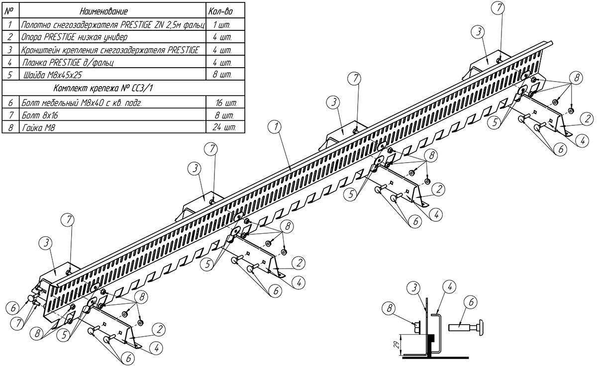
Understanding complex systems is crucial in various fields, and visual representations play a vital role in this process. These schematics offer clarity, enabling professionals to analyze and optimize intricate workflows efficiently. By mapping out components and their interactions, teams can streamline operations and enhance communication across departments.
| Industry | Application |
|---|---|
| Manufacturing | Optimizing production lines for efficiency and reducing downtime. |
| Software Development | Visualizing system architecture and enhancing collaborative coding efforts. |
| Healthcare | Improving patient flow and resource allocation in medical facilities. |
| Logistics | Mapping out supply chain processes to minimize delays and costs. |
Safety Considerations in BCS Systems
Ensuring the security and reliability of control systems is paramount for optimal operation. Various factors contribute to the safe functioning of these systems, requiring careful assessment and proactive measures.
Key Risks and Challenges
- Equipment malfunctions leading to system failures
- Inadequate training of personnel handling critical components
- External threats such as cyberattacks
Preventive Measures
- Regular maintenance and inspections of all system elements
- Implementing robust training programs for staff
- Utilizing advanced security protocols to safeguard against breaches
Future Trends in BCS Documentation
The evolution of technical documentation is set to transform the way information is structured and accessed. As industries move towards greater efficiency and automation, the need for dynamic, easily navigable content will increase. This shift will enhance user experience, facilitating better understanding and utilization of complex systems.
| Trend | Description |
|---|---|
| Interactive Formats | Emphasis on multimedia elements to create engaging and informative materials. |
| AI Integration | Utilization of artificial intelligence for automated updates and personalized content delivery. |
| Cloud-Based Solutions | Migration towards online platforms for easier collaboration and real-time access. |
| Enhanced Search Capabilities | Improved indexing and search functions for quicker information retrieval. |
Resources for Learning More About BCS
For those seeking to deepen their understanding of this essential machinery, a variety of resources are available. These materials provide insights into the mechanisms, functionality, and applications of the components, helping enthusiasts and professionals alike enhance their knowledge base.
Books and Manuals

Numerous publications offer detailed explanations and illustrations of the subject matter. Technical manuals often serve as a comprehensive guide, while specialized books delve into specific aspects, making them invaluable for both novices and experts.
Online Courses and Webinars
Digital learning platforms present a wealth of courses that cater to different levels of expertise. Webinars conducted by industry professionals can provide real-time insights, allowing participants to engage and ask questions, further enhancing their understanding.