Understanding the Carrier Parts Diagram for Better Maintenance
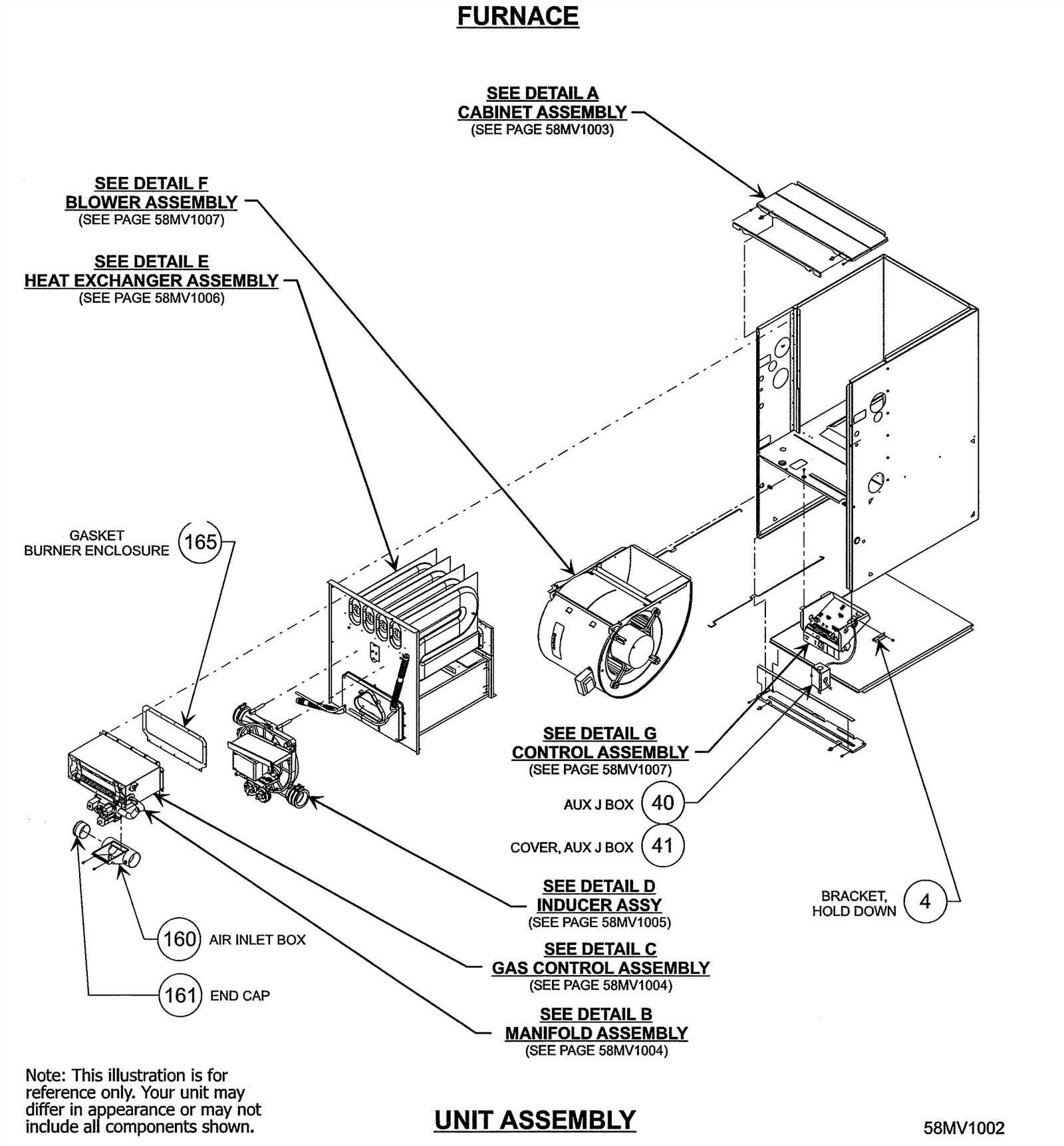
In the world of machinery, the intricate relationship between various components plays a pivotal role in ensuring optimal functionality. Each segment of a system contributes to the overall performance, requiring a comprehensive grasp of how they interact and depend on one another. This interconnectedness is crucial for diagnosing issues, performing maintenance, and enhancing efficiency.
Visual representations of these mechanical structures are invaluable tools for both engineers and technicians. They provide a clear and organized overview, allowing for easier identification of individual elements and their respective functions. Such illustrations serve as a guide, illuminating the complex interplay between various units and fostering a deeper understanding of the assembly.
Moreover, mastering the layout of these assemblies can significantly streamline the troubleshooting process. When familiar with the arrangement, one can swiftly locate problems and implement solutions, minimizing downtime and ensuring the longevity of the machinery. This knowledge is essential for anyone involved in the operation or maintenance of sophisticated equipment.
Understanding Carrier Parts Diagram
Comprehending the layout of mechanical components is essential for effective maintenance and troubleshooting. This visual representation serves as a crucial tool, providing insights into the interconnections and functionalities of various elements within a system. By examining this schematic, one can easily identify how each segment contributes to the overall operation.
These illustrations typically include labeled sections that guide users through the intricate relationships between different features. The use of symbols and lines helps clarify the flow of processes, making it easier to pinpoint potential issues or areas that require attention.
Familiarity with such layouts enhances one’s ability to perform repairs or modifications, leading to improved efficiency and reduced downtime. Understanding these visuals not only aids in immediate problem-solving but also fosters a deeper appreciation for the engineering behind the design.
Importance of Carrier Parts Diagrams
Understanding the layout and components of complex machinery is essential for effective maintenance and repair. Visual representations of mechanical structures provide crucial insights, aiding technicians and engineers in identifying individual elements and their functions. This clarity not only enhances troubleshooting processes but also promotes efficient assembly and disassembly.
Facilitating Maintenance and Repair
Clear visual guides serve as a reference point for professionals, enabling them to perform tasks with precision. By detailing the arrangement and interconnections of various elements, these illustrations reduce the likelihood of errors during service interventions. Additionally, they streamline training for new personnel, equipping them with the necessary knowledge to handle equipment confidently.
Enhancing Communication
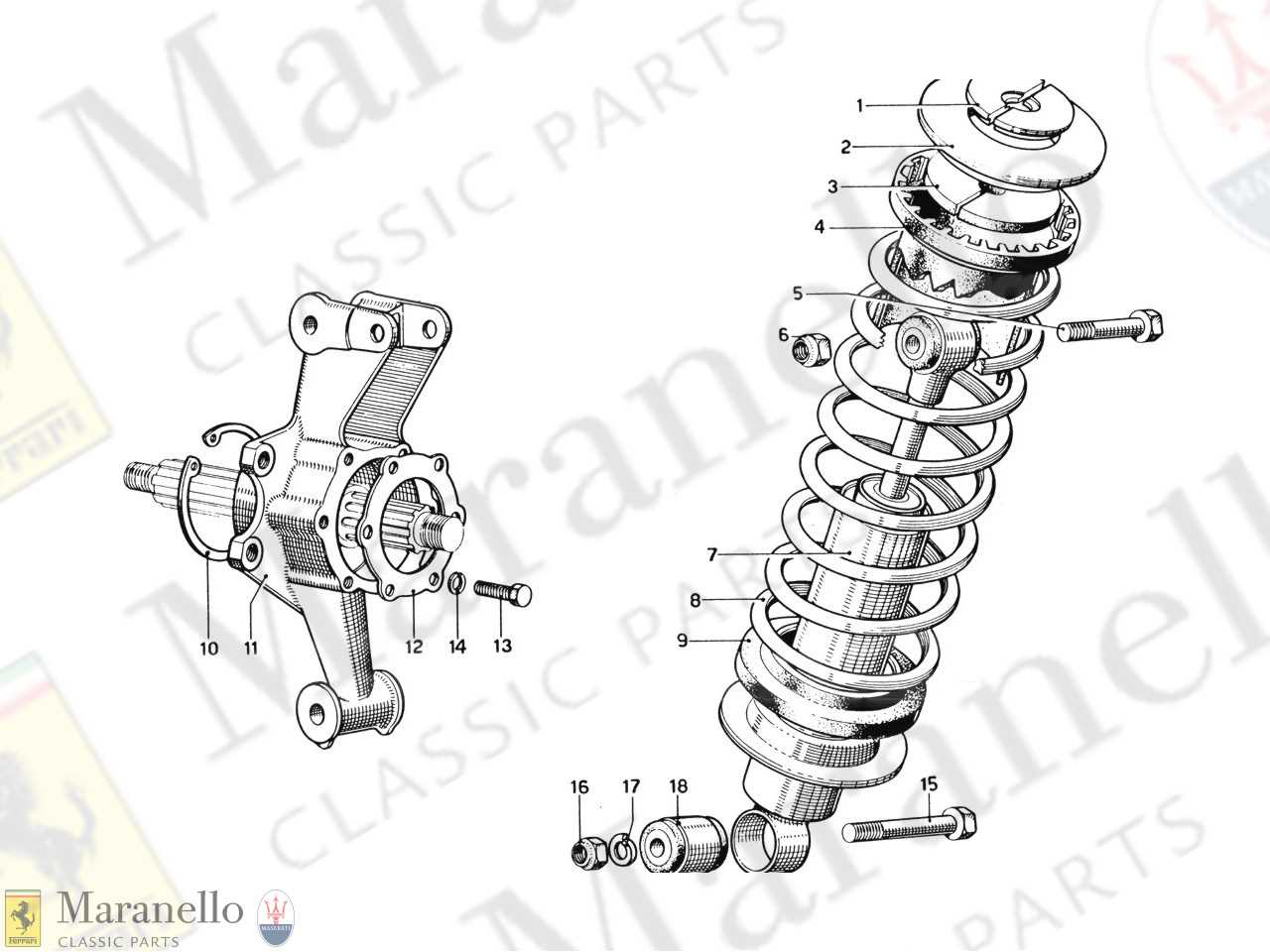
Effective communication among team members is vital in any technical environment. Visual aids bridge gaps in understanding by providing a common framework. When discussing modifications, upgrades, or troubleshooting strategies, referring to these illustrations ensures everyone is on the same page, fostering collaboration and improving overall efficiency.
| Benefits | Description |
|---|---|
| Improved Clarity | Visual aids simplify complex structures, making it easier to comprehend functions and relationships. |
| Reduced Errors | Clear representations minimize mistakes during repairs or maintenance tasks. |
| Training Support | New technicians can quickly learn about systems with visual references. |
| Team Collaboration | Common visual tools enhance communication and collaboration among team members. |
Components of Carrier Systems
The efficiency and functionality of transportation mechanisms are rooted in a diverse array of elements working cohesively. Each segment plays a crucial role, ensuring that the entire system operates smoothly and effectively. Understanding these fundamental components is essential for anyone involved in design, maintenance, or enhancement of these systems.
Key components include:
- Framework: The structural base that supports the entire assembly.
- Drive Mechanism: The system responsible for propulsion, converting energy into motion.
- Load Support: Elements designed to bear and distribute the weight of transported items.
- Control System: Interfaces and sensors that allow for operational management and monitoring.
- Safety Features: Devices and mechanisms that ensure secure operation and protect against failures.
In addition to these core elements, there are various ancillary systems that enhance performance:
- Power Supply: The source of energy necessary for operation.
- Communication Tools: Technologies that facilitate interaction between different components and operators.
- Maintenance Equipment: Tools and systems designed for regular upkeep and repair.
Each of these elements contributes to the overall effectiveness and reliability of transportation systems, highlighting the intricate design and engineering behind their operation.
How to Read Diagrams Effectively
Understanding visual representations of complex systems is essential for efficient problem-solving and communication. Mastering the art of interpreting these illustrations can significantly enhance your ability to analyze and work with intricate information. This section outlines key strategies to improve your comprehension of such graphical content.
1. Familiarize Yourself with Symbols
Before diving into the visual representation, it’s crucial to recognize the various symbols used. Different fields often utilize unique icons to convey specific meanings. Take time to review the legend or key provided, which serves as a guide to interpreting these symbols accurately.
2. Break Down the Components
Dividing the illustration into smaller, manageable sections can make it easier to digest. Focus on one area at a time, analyzing its relationship with adjacent elements. This systematic approach enables you to build a comprehensive understanding piece by piece.
| Component | Description |
|---|---|
| Symbols | Icons representing specific functions or components. |
| Connections | Lines or arrows indicating relationships or flow of information. |
| Labels | Text that provides additional context or identification for elements. |
By applying these techniques, you can enhance your proficiency in interpreting visual illustrations, leading to improved insights and decision-making capabilities.
Common Symbols Used in Diagrams
Understanding the various icons and representations in technical illustrations is essential for effective communication and comprehension. These symbols serve as a universal language, conveying complex information in a simplified manner. By familiarizing oneself with these graphical elements, one can navigate through intricate systems more efficiently.
Among the frequently encountered representations are geometric shapes, each symbolizing different components or functions within the system. For instance, circles often denote connection points, while rectangles may indicate processes or operations. Additionally, arrows play a critical role in illustrating the flow of information or energy, guiding the observer through the interconnected elements.
Moreover, standardized symbols ensure consistency across different fields, allowing professionals from various backgrounds to interpret illustrations accurately. Understanding the meaning behind each symbol enhances one’s ability to analyze and troubleshoot systems effectively, fostering better collaboration among team members.
In summary, mastering the symbols used in technical representations not only aids in individual understanding but also promotes clear communication within teams. By recognizing and interpreting these visual cues, one can navigate complex systems with confidence and clarity.
Types of Carrier Systems Illustrated
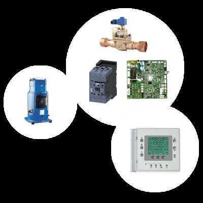
This section explores various frameworks and mechanisms utilized in transportation and logistics, highlighting their unique structures and functionalities. Understanding these systems is crucial for optimizing efficiency and performance in various applications.
Modular Systems
Modular frameworks are designed for flexibility and adaptability. They consist of interlocking components that can be easily rearranged or replaced, allowing for quick modifications to meet changing demands. This type of system is especially beneficial in dynamic environments where operational requirements frequently evolve.
Integrated Solutions
Integrated solutions combine multiple elements into a cohesive unit, streamlining processes and enhancing productivity. These comprehensive setups often feature advanced technologies that facilitate seamless communication between different components, resulting in improved coordination and reduced operational delays.
In summary, understanding the various configurations available enhances the ability to choose the most suitable option for specific needs. By examining these illustrated systems, one can better appreciate the complexities and innovations that drive efficiency in modern logistics.
Maintenance Tips for Carrier Parts
Ensuring the longevity and efficiency of your equipment requires regular care and attention. By following a few straightforward guidelines, you can significantly enhance performance and reduce the likelihood of unexpected issues.
- Regular Inspections: Conduct frequent checks to identify wear and tear before they escalate into major problems.
- Clean Components: Dust and debris can hinder functionality. Keep all surfaces clean to promote optimal operation.
- Lubrication: Apply appropriate lubricants to moving elements to minimize friction and prevent damage.
In addition to these practices, here are some specific recommendations:
- Monitor Operating Conditions: Keep an eye on temperature and pressure readings to ensure everything is functioning within the desired range.
- Replace Worn Elements: Do not hesitate to swap out any component showing signs of fatigue to maintain efficiency.
- Follow Manufacturer Guidelines: Always adhere to the recommendations provided by the manufacturer for optimal care and maintenance.
Implementing these strategies can help ensure reliable operation and extend the lifespan of your equipment. Regular attention and proactive measures are key to preventing costly repairs and downtime.
Identifying Parts through Diagrams
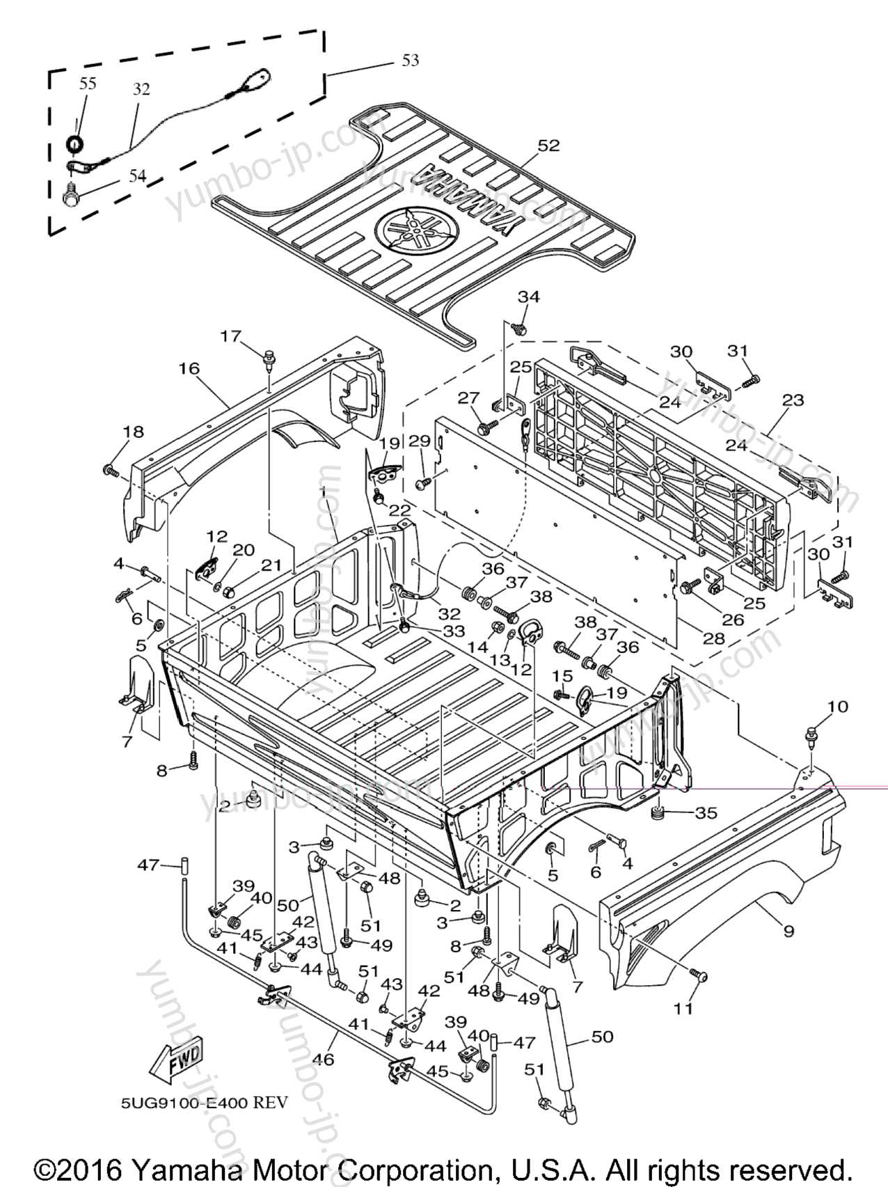
Understanding the layout and functionality of various components is essential for effective maintenance and repair. Visual representations serve as invaluable tools, offering a clear depiction of each element’s position and interconnection. This approach enhances the ability to pinpoint specific items, facilitating a smoother workflow when addressing issues.
Visual aids simplify complex structures, allowing users to grasp the arrangement of elements at a glance. By analyzing these illustrations, technicians can quickly identify which components require attention or replacement. The clarity provided by such graphics eliminates confusion and aids in ensuring accurate diagnostics.
Familiarity with these visual guides also enhances one’s ability to communicate effectively within a team. When discussing repairs or modifications, referring to a common reference point ensures that all members are aligned in their understanding, reducing the risk of errors. Moreover, these illustrations often include labels and notes that further clarify the function of each component, making them indispensable for both novice and experienced professionals.
Applications of Carrier Parts Diagrams
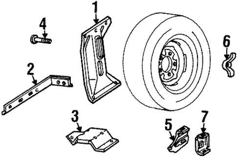
Visual representations of components play a crucial role in various industries, offering clarity and insight into complex systems. These illustrations facilitate understanding, maintenance, and troubleshooting, making them indispensable for engineers, technicians, and operators alike.
One primary use of these illustrations is in technical documentation. They provide a clear reference for assembly and disassembly processes, enabling users to follow step-by-step instructions without confusion. This is especially beneficial in manufacturing environments where precision is paramount.
In maintenance and repair scenarios, such visuals serve as vital tools for diagnosing issues. Technicians can quickly identify malfunctioning elements, streamline repair procedures, and minimize downtime. This efficiency translates into cost savings and enhanced productivity for organizations.
Training is another significant application. New employees can learn about system layouts and component functions through these visuals, accelerating their onboarding process. Interactive training sessions often incorporate these representations to foster a better understanding of complex machinery.
Moreover, these visual aids are valuable in communication among team members. They help convey technical information clearly, reducing the likelihood of misunderstandings. This is particularly important in multidisciplinary teams where professionals from diverse backgrounds collaborate on projects.
In summary, visual representations of components enhance documentation, maintenance, training, and team communication, playing an integral role in the efficiency and effectiveness of various industries.
Software Tools for Diagram Creation
In today’s digital landscape, the ability to visually represent complex information is essential. Various applications exist to facilitate the crafting of illustrative representations, enabling users to convey ideas more effectively. These tools offer diverse functionalities, catering to both professionals and amateurs alike, ensuring a seamless experience in creating visual aids.
One popular category of applications includes vector graphics editors, which provide users with the flexibility to design intricate visuals with precision. These programs often come with an array of shapes, lines, and customizable features that allow for detailed customization. Users can easily manipulate elements to create clear and engaging visuals.
Another vital group comprises specialized software designed specifically for creating visual outlines and schematics. These platforms often include built-in templates and smart features that streamline the process, making it easier to organize thoughts and present information logically. With intuitive interfaces, they empower users to produce professional-looking visuals in a fraction of the time.
Collaboration tools also play a crucial role in the development of visual content. Many of these applications allow multiple users to work on the same project simultaneously, enhancing teamwork and creativity. Real-time feedback and sharing options enable seamless communication, fostering an environment where ideas can flourish.
In conclusion, the variety of software solutions available today provides individuals with the tools they need to create compelling visual representations. Whether for educational, professional, or personal use, these applications enhance the ability to communicate complex ideas clearly and effectively.
Case Studies of Diagram Usage
This section explores practical applications of visual schematics across various industries. Understanding how these representations facilitate problem-solving, enhance communication, and streamline processes can provide valuable insights for professionals seeking efficiency and clarity in their work.
Several notable instances illustrate the effectiveness of these visual tools:
-
Manufacturing Sector:
In a prominent automotive company, engineers utilized schematics to optimize assembly line operations. By mapping out component relationships, they identified bottlenecks and redesigned workflows, resulting in a 15% increase in productivity.
-
Healthcare Industry:
A hospital implemented visual representations of patient care pathways. This approach improved staff communication and reduced patient wait times by clearly outlining responsibilities and processes.
-
Software Development:
In a tech startup, developers created visual layouts for system architecture. This helped clarify dependencies and streamline collaboration, leading to a 20% reduction in project completion time.
-
Education:
An educational institution adopted visual models for curriculum design. By clearly outlining course connections, they enhanced interdisciplinary learning, making it easier for students to understand the relevance of their studies.
These examples underscore the transformative power of visual schematics in diverse fields, highlighting their role in fostering understanding and driving innovation.
Troubleshooting Using Carrier Diagrams
Effective problem-solving in complex systems often requires a detailed visual reference. These visual aids serve as essential tools, enabling technicians to pinpoint issues quickly and accurately. By following these illustrated guides, professionals can streamline their diagnostic processes and reduce downtime.
Understanding the Layout
Familiarity with the configuration of components is crucial. Each illustration provides a comprehensive view, helping users identify the location and function of various elements. Recognizing the arrangement allows for efficient navigation when issues arise.
Identifying Common Issues
Visual resources often highlight typical malfunctions, which can aid in rapid diagnosis. Technicians can compare symptoms with the information presented, making it easier to determine the source of a problem without unnecessary guesswork.
Guided Repairs
Step-by-step instructions often accompany these visuals, detailing the repair process. By following these guidelines, professionals can execute fixes confidently, ensuring that all necessary steps are taken to resolve the issue effectively.
Preventive Maintenance
Utilizing visual references not only aids in troubleshooting but also enhances preventive strategies. Regular review of component layouts and potential failure points can inform maintenance schedules, reducing the likelihood of future disruptions.
In summary, leveraging visual aids in technical troubleshooting fosters a more efficient and systematic approach to resolving issues in complex systems.
Future Trends in Carrier Technology
As industries continue to evolve, the technological landscape surrounding logistics and transportation is poised for significant transformation. Innovations are emerging that promise to enhance efficiency, improve safety, and reduce environmental impact, paving the way for a more integrated and responsive system. These advancements will redefine operational capabilities and user experiences across various sectors.
One major trend is the increasing adoption of automation and artificial intelligence. By implementing smart systems, organizations can streamline operations, optimize routes, and minimize downtime. This shift towards autonomous solutions not only boosts productivity but also allows for more precise tracking and management of resources.
Moreover, sustainability is becoming a central focus. The integration of green technologies, such as electric and hydrogen-powered vehicles, is set to revolutionize traditional methodologies. Companies are actively seeking to reduce their carbon footprint, and as a result, eco-friendly practices will likely become the standard rather than the exception.
Data analytics is also playing a crucial role in shaping the future landscape. Leveraging big data allows for better forecasting, enhancing decision-making processes. Organizations can analyze trends and customer behaviors more effectively, tailoring their services to meet evolving demands.
In summary, the future of logistics technology is bright, characterized by innovation, sustainability, and smarter operations. As these trends continue to develop, they will undoubtedly transform how goods and services are delivered, making the entire system more efficient and resilient.