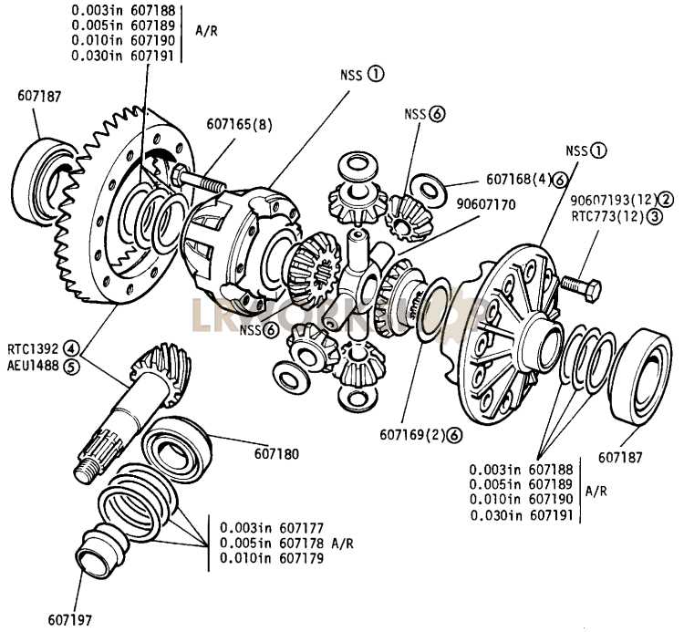
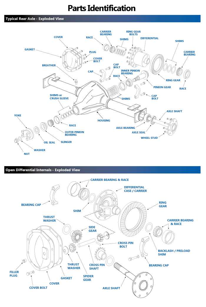
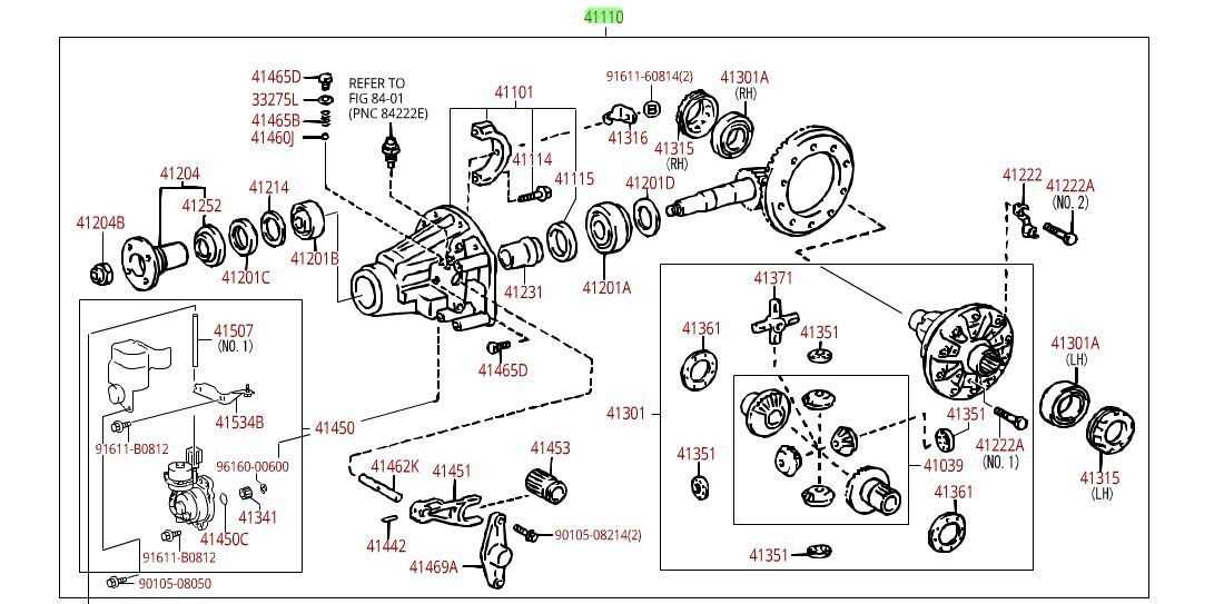
Understanding the Differential Parts Diagram for Enhanced Mechanical Insights

In the realm of automotive engineering, the intricacies of power distribution play a crucial role in vehicle performance. This section explores the essential components that contribute to the seamless transfer of torque among the wheels, ensuring optimal handling and stability.
By examining the various elements involved, readers will gain insight into how these components interact to enhance driving dynamics. A comprehensive understanding of this mechanism not only highlights its importance but also lays the groundwork for appreciating advancements in automotive technology.
Through detailed illustrations and explanations, we will delve into the underlying structure, revealing how each segment functions within the larger system. Ultimately, this exploration aims to provide a clearer picture of how effective distribution can significantly impact the overall driving experience.
Differential Parts Diagram Explained
This section aims to provide a comprehensive overview of the components that play a crucial role in the functioning of a specific mechanical system. Understanding these elements is essential for grasping how they interact and contribute to overall performance.
Each element has a distinct function, and when combined, they ensure smooth operation and reliability. Below is a summary of the key components:
| Component | Function |
|---|---|
| Gear Set | Transfers power and adjusts torque. |
| Carrier | Supports the gear assembly and facilitates movement. |
| Case | Houses all components and protects them from external elements. |
| Seals | Prevent fluid leakage and contamination. |
Each of these elements works in harmony, enabling the system to achieve its ultimate purpose effectively and efficiently.
Understanding the Differential Functionality
This section explores the essential mechanism that enables vehicles to navigate smoothly, particularly when turning. It highlights how specific components interact to distribute power effectively, ensuring optimal traction and stability across various driving conditions.
The core function revolves around allowing wheels on the same axle to rotate at different speeds. This capability is crucial when a vehicle takes a curve, as the outer wheels travel a longer distance than the inner ones. Without this system, handling would be severely compromised, leading to difficulties in steering and increased tire wear.
Moreover, the functionality enhances overall performance by improving maneuverability. It plays a pivotal role in maximizing grip, allowing drivers to maintain control while adapting to diverse terrains and conditions.
Understanding this mechanism’s intricacies helps appreciate its importance in modern automotive design. As technology advances, innovations continue to enhance its efficiency, further contributing to safety and driving pleasure.
Key Components of a Differential
This section explores the essential elements that contribute to the functionality of a key mechanism in automotive systems. Understanding these components is crucial for grasping how power is transmitted and managed within vehicles.
Core Elements
- Gear Set
- Carrier Assembly
- Input Shaft
- Output Shafts
Supporting Components

- Bearings
- Seals
- Housing
- Lubrication System
Each of these elements plays a vital role in ensuring smooth operation and efficiency in vehicle dynamics.
Types of Differentials in Vehicles

Understanding the various mechanisms that facilitate power distribution to the wheels is crucial for vehicle performance and handling. These systems play a pivotal role in ensuring that wheels can rotate at different speeds, particularly when navigating curves, enhancing traction and stability on diverse terrains.
One common type is the open variant, which provides basic functionality by allowing the wheels to turn at varying rates. This system is simple and cost-effective but may struggle with traction in low-grip conditions.
Another type is the limited-slip configuration, designed to improve grip by transferring power to the wheel with better traction. This mechanism is beneficial for performance-oriented applications and off-road scenarios.
The locking system takes this a step further, enabling both wheels on an axle to rotate in unison when needed. This feature is particularly useful in challenging driving conditions, such as mud or snow, where consistent wheel speed is essential.
Finally, electronic variations utilize sensors and control units to adjust power distribution dynamically. These advanced systems can optimize handling and traction by responding to real-time driving conditions, making them increasingly popular in modern vehicles.
Importance of Proper Diagram Usage
Utilizing accurate visual representations in any technical or educational field is crucial for effective communication and understanding. These illustrations serve as essential tools that facilitate the comprehension of complex information, allowing individuals to grasp concepts more swiftly and accurately.
Enhanced Understanding
When visual elements are correctly employed, they contribute significantly to learning and retention. Here are some benefits of effective visualization:
- Clarification of Concepts: Visual aids simplify intricate ideas, breaking them down into manageable components.
- Improved Memory: People tend to remember images better than text, enhancing recall.
- Engagement: Well-designed visuals capture attention, making the learning experience more interactive.
Effective Communication
Clear illustrations also play a vital role in facilitating discussions among professionals and stakeholders. Key advantages include:
- Common Language: Visuals create a universal means of communication, bridging gaps between diverse backgrounds.
- Focus on Key Points: They highlight critical information, guiding conversations towards essential issues.
- Reduction of Misunderstandings: Accurate representations minimize the risk of misinterpretation, fostering clarity.
In conclusion, the proper use of visuals not only enhances understanding and communication but also plays a fundamental role in successful outcomes across various disciplines.
Common Issues in Differential Systems
Understanding the challenges that arise in the functioning of complex mechanical assemblies is crucial for ensuring optimal performance. These complications can stem from various sources, leading to inefficiencies, increased wear, and potential system failures. Identifying and addressing these issues can enhance reliability and longevity.
Some frequent complications encountered in these systems include:
| Issue | Description | Possible Solutions |
|---|---|---|
| Wear and Tear | Components may degrade over time due to friction and load. | Regular maintenance, lubrication, and timely replacements. |
| Misalignment | Parts may not be properly aligned, leading to uneven load distribution. | Realignment procedures and use of precision tools. |
| Overheating | Excessive heat can cause material failure and reduce efficiency. | Improved cooling systems and regular temperature monitoring. |
| Noise and Vibration | Unusual sounds can indicate underlying problems, such as loose components. | Inspection and tightening of fasteners, along with balancing. |
| Fluid Leaks | Leaks can lead to loss of essential lubricants, affecting performance. | Regular checks and prompt repair of seals and gaskets. |
By being aware of these common problems and implementing effective solutions, operators can significantly enhance the efficiency and reliability of their mechanical systems.
Maintenance Tips for Differentials
Ensuring the longevity and optimal performance of your vehicle’s components requires regular attention and care. This section provides essential guidance for keeping these critical mechanisms in peak condition. Adhering to a proper maintenance routine can prevent costly repairs and enhance the overall driving experience.
Regular Inspections
Conduct frequent checks on fluid levels and conditions. Look for signs of leaks or contamination, which may indicate underlying issues. It’s advisable to inspect seals and gaskets for wear, as these components play a vital role in preventing fluid loss.
Fluid Changes
Timely replacement of lubricants is crucial. Follow the manufacturer’s recommendations for intervals and types of fluids. Using the right lubricant helps ensure smooth operation and reduces friction, extending the life of the internal components. Always dispose of old fluids responsibly.
How to Read a Parts Diagram
Understanding a visual representation of components is essential for effective assembly and maintenance. This guide will help you interpret these illustrations, ensuring you grasp the relationships and functions of each element. By familiarizing yourself with key features, you’ll navigate the image with confidence.
Begin by identifying the legend or key, which provides explanations for symbols and colors used in the visual representation. This will serve as your roadmap.
| Symbol | Description |
|---|---|
| Circle | Indicates a joint or connection point |
| Square | Represents a fixed component |
| Arrow | Shows the direction of movement or flow |
Next, pay attention to the arrangement and numbering of elements. This organization reveals how parts fit together and function cohesively. Following the sequence will guide you through assembly or disassembly processes.
Finally, cross-reference with the accompanying documentation. This provides additional details on specifications and operational procedures, enhancing your understanding and execution of tasks.
Diagram Symbols and Their Meanings
Understanding the visual representations used in technical illustrations is crucial for effective communication in engineering and design. Each symbol serves a specific purpose, conveying essential information quickly and clearly. Recognizing these symbols can significantly enhance comprehension and collaboration among professionals.
Commonly Used Symbols
In the realm of technical visuals, several symbols are frequently employed. For example, a circle often indicates a junction or connection point, while a square may represent a component or unit within the system. Additionally, arrows typically denote the direction of flow or movement, guiding the viewer’s understanding of the process depicted.
Symbol Interpretation
Interpreting these representations requires familiarity with industry standards. Some symbols might vary between disciplines, yet most follow a universal logic. For instance, a dashed line often signifies an auxiliary path or a hidden element, whereas a solid line indicates a direct relationship or physical connection. Mastery of these meanings allows professionals to analyze and troubleshoot designs effectively.
Creating Your Own Differential Diagram
Crafting a visual representation of mechanical elements can enhance your understanding of complex systems. This process involves organizing components and their relationships, allowing for a clearer grasp of their functions and interactions. By designing your own visual layout, you can tailor the information to suit specific needs or preferences, making it an invaluable tool for learning and communication.
To begin, follow these essential steps:
| Step | Description |
|---|---|
| 1. Identify Components | List all the key elements that will be included in your visual representation. |
| 2. Determine Relationships | Analyze how these elements interact and affect each other. |
| 3. Choose a Layout | Select a suitable format for displaying the components, such as circular, hierarchical, or linear. |
| 4. Use Software Tools | Utilize graphic design programs or online platforms to create a polished version of your layout. |
| 5. Review and Revise | Critique your representation for clarity and accuracy, making adjustments as necessary. |
Engaging in this creative process not only deepens comprehension but also fosters innovation. By visualizing mechanical interactions, you can identify areas for improvement or new applications, ultimately enhancing your overall expertise in the field.
Applications in Automotive Engineering
In the realm of automotive engineering, the utilization of intricate mechanical configurations plays a crucial role in enhancing vehicle performance and efficiency. These assemblies are essential for the transmission of power from the engine to the wheels, ensuring smooth operation across various driving conditions.
One significant application lies in the optimization of traction and handling. By employing these complex systems, engineers can fine-tune how power is distributed to individual wheels, improving stability during acceleration and cornering. This capability is particularly vital for high-performance vehicles that demand precise control.
Another important aspect involves enhancing fuel efficiency. By strategically designing these systems, automotive engineers can reduce energy loss, leading to better mileage. This not only benefits consumers but also aligns with global efforts to promote sustainability in transportation.
Moreover, the integration of advanced technologies such as electronic control units allows for real-time adjustments. This adaptability means that vehicles can respond dynamically to changing road conditions, providing a safer and more comfortable driving experience. Such innovations reflect the ongoing evolution in automotive design, driven by the need for both performance and environmental responsibility.
Comparing Open and Limited Slip Differentials
Understanding the differences between various power distribution mechanisms is crucial for optimizing vehicle performance. Two common types are those that allow wheels to rotate at different speeds and those that provide better traction under varying conditions. Each has its unique characteristics and advantages, making them suitable for different driving scenarios.
Open Mechanisms
Open systems are straightforward in design and function. They allow the wheels to turn independently, which is beneficial for smooth cornering. However, they can struggle in low-traction situations, as power may transfer to the wheel with less grip, leading to loss of control.
Limited Slip Mechanisms
In contrast, limited slip systems enhance traction by distributing power more effectively between wheels. These mechanisms can engage under certain conditions, providing additional grip when needed. As a result, they are often favored for performance driving and off-road conditions, where maintaining traction is paramount. The choice between these two systems ultimately depends on driving needs and conditions.
Future Trends in Differential Technology
The evolution of mechanisms that manage torque distribution is rapidly advancing, driven by innovations in engineering and increasing demands for efficiency and performance. As we look to the future, several key trends are emerging that promise to transform how these systems operate, enhancing vehicle dynamics and overall driving experience.
Integration of Smart Technologies
The incorporation of intelligent systems is poised to revolutionize torque management solutions. With advancements in artificial intelligence and machine learning, future mechanisms will be able to adapt in real-time to varying road conditions and driver behavior. This adaptability will not only improve handling but also contribute to safety by reducing the likelihood of skidding or loss of traction.
Electric and Hybrid Applications

The shift towards electric and hybrid vehicles is significantly influencing the development of torque distribution systems. Innovative designs that utilize electric motors to provide instantaneous torque are becoming more prevalent. This allows for precise control and enhances the efficiency of power transfer, ultimately leading to improved performance and reduced energy consumption in modern vehicles.