FS 131 Parts Diagram Overview and Components Guide
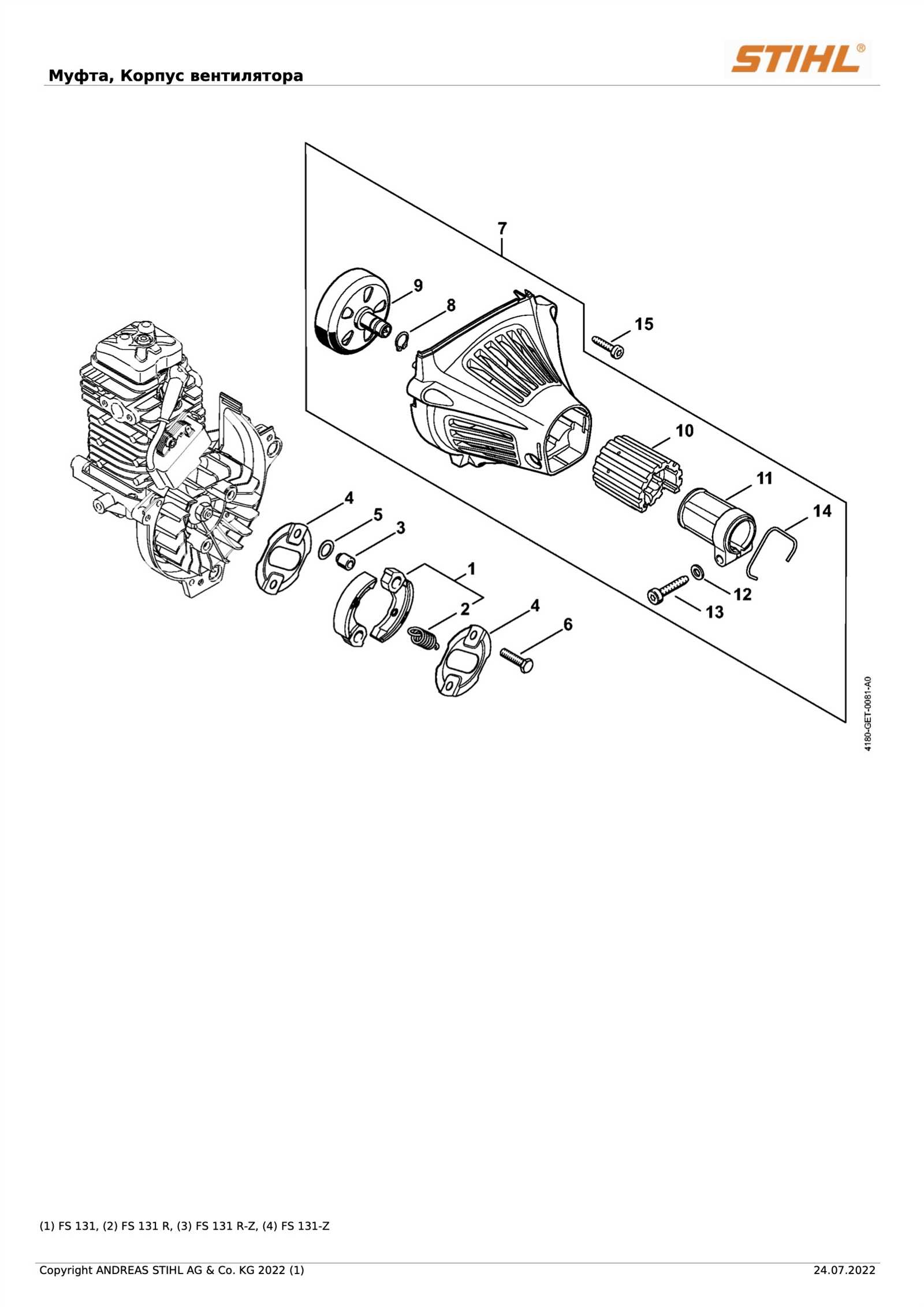
In this guide, we will delve into the configuration of critical elements that make up a reliable and powerful tool. These elements are integral to its functionality, ensuring smooth operation and long-term durability. By familiarizing yourself with the placement and role of these components, you can enhance your understanding and make informed decisions regarding maintenance and repairs.
The arrangement of different units plays a key role in how effectively the system operates. Knowing where each part is located and how it interacts with others can help prevent issues and improve overall performance. Whether you are an experienced technician or a casual user, this information will be valuable in keeping the equipment in optimal condition.
Additionally, understanding the internal workings and proper connections allows for easier troubleshooting. Clear knowledge of how the various segments fit together enables you to identify potential problems early and address them efficiently.
Understanding the FS 131 Components Layout
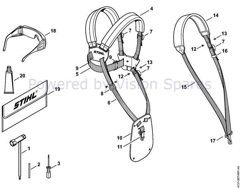
Grasping the structure and arrangement of this equipment is crucial for anyone looking to maintain or repair it effectively. The internal and external elements are organized in a way that maximizes both efficiency and ease of access. Familiarity with the key areas allows for smoother operation and quicker troubleshooting when issues arise.
Each section plays a vital role in the overall function of the machine. From the power source to the intricate mechanical parts, understanding the connections between them ensures proper handling and minimizes the risk of damage during use. Knowing where each component fits in the bigger picture aids in keeping the device running smoothly.
Additionally, regular checks of the system’s layout help identify any wear and tear, making it easier to replace or adjust specific areas as needed. This not only extends the lifespan of the equipment but also ensures optimal performance during prolonged use.
Key Mechanical Parts Overview
This section provides a concise description of essential structural components commonly found in mechanical systems. The aim is to highlight the primary elements involved in the system’s functionality, offering a clear understanding of how these units work together to achieve efficient operation.
Core Components
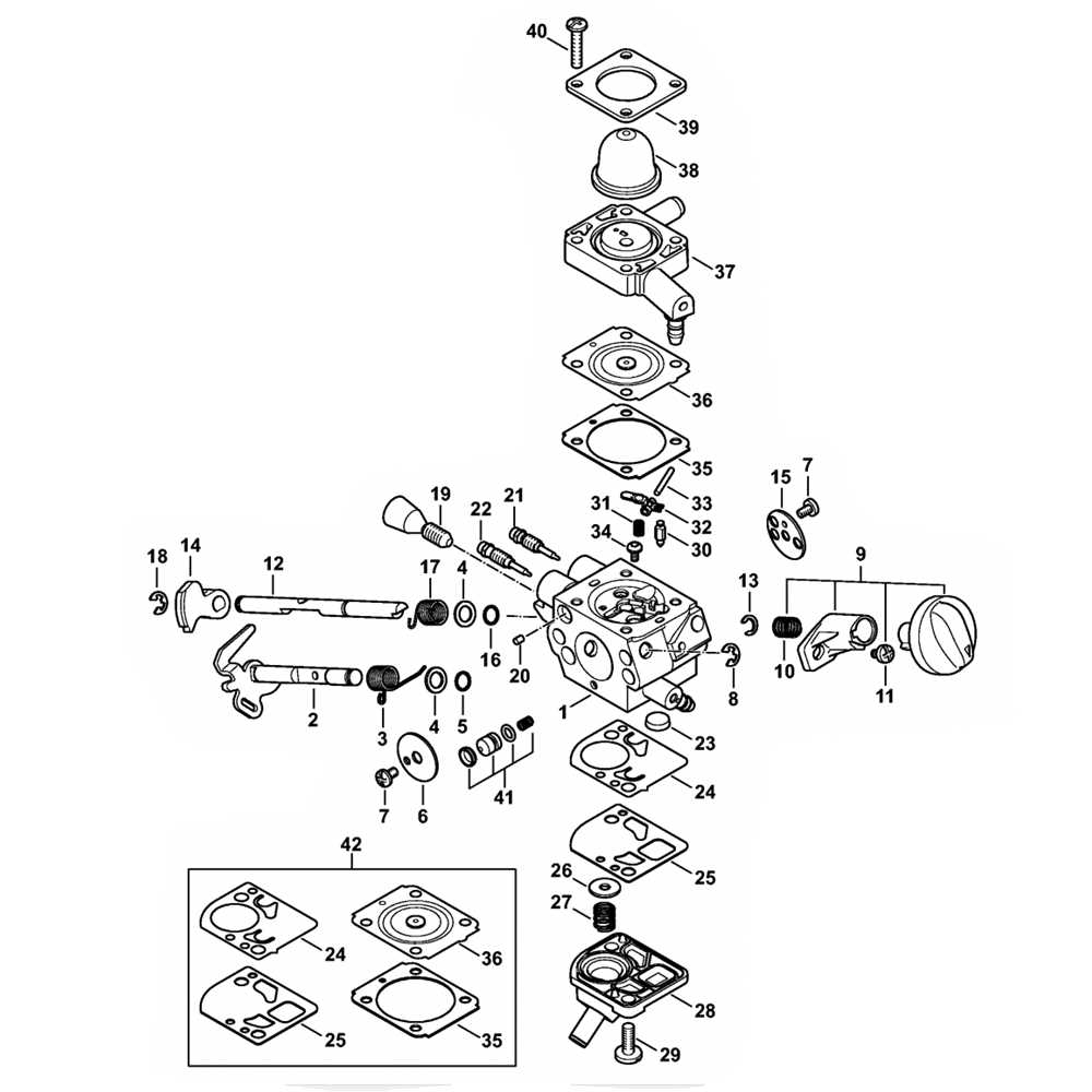
Among the critical elements are the power source, which initiates movement, and the transmission mechanism, responsible for transferring energy. These core elements ensure that the device performs its intended tasks with reliability. Proper synchronization between these units is vital for optimal performance.
Operational Mechanisms
Another significant aspect of the system includes control mechanisms, which regulate motion and direction. These components work together with the primary structural units to deliver precision and stability during use.
| Component | Description |
|---|---|
| Power Source | Generates the initial force required for operation. |
| Transmission Mechanism | Transfers energy from the power source to other units. |
| Component | Function |
|---|---|
| Rubber Bushings | Absorb high-frequency vibrations and prevent direct contact between metal parts. |
| Spring Dampers | Provide flexibility to absorb shock and vibrations, restoring equilibrium. |
| Hydraulic Shock Absorbers | Use fluid to convert kinetic energy into heat, significantly reducing movement. |
Throttle and Carburetor Connection
Establishing a reliable link between the throttle control mechanism and the fuel mixing system is essential for optimal engine performance. This connection ensures that the engine responds efficiently to the operator’s commands, maintaining power and fuel efficiency. A well-maintained interface between these components allows smooth acceleration and precise control over the engine’s speed and output.
Key Components of the Connection
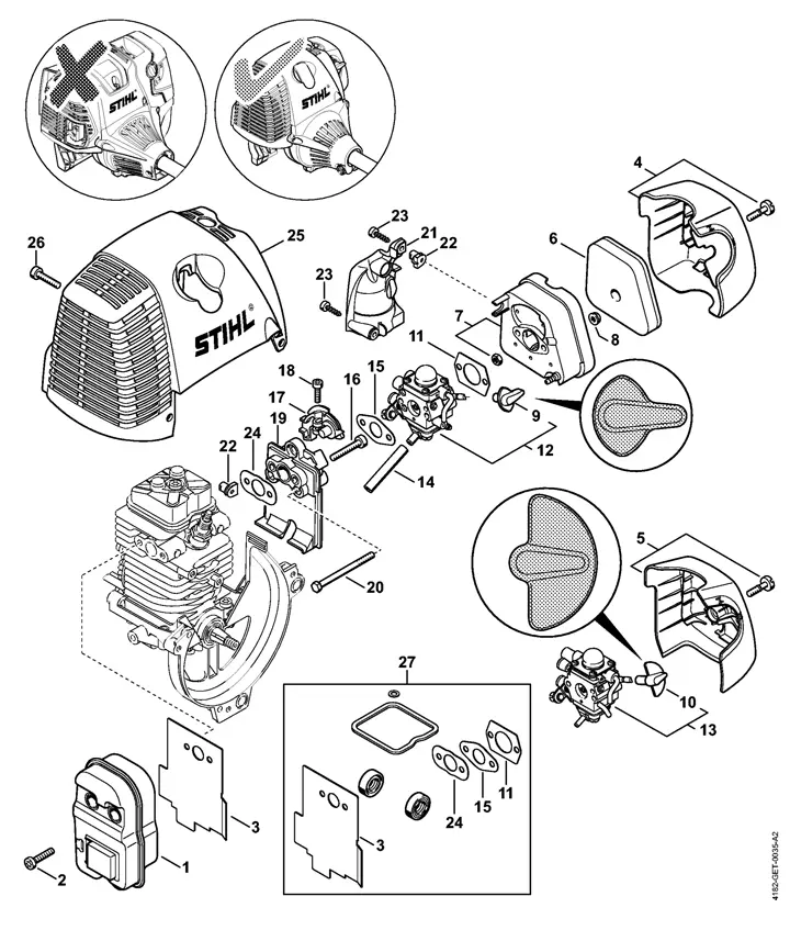
The primary elements involved in this connection include the throttle cable, the lever system, and the fuel regulating device. The throttle cable transmits the input from the user to the governing mechanism, while the lever system adjusts the air-fuel mixture. Together, these parts work in harmony to provide seamless engine control.
Importance of Proper Alignment
Correct positioning and tensioning of the throttle cable are crucial for ensuring that the system responds promptly and accurately. Any misalignment or slack in the cable can lead to sluggish or erratic engine behavior, reducing performance and efficiency. Regular inspection and maintenance of this connection are necessary for long-lasting, trouble-free operation.
Drive Shaft and Gearhead Design
The design of the transmission system is crucial in ensuring the smooth transfer of mechanical power from the engine to the working components. This involves carefully engineered elements that work in unison to optimize performance and efficiency. The main focus is on two key components: the rotating shaft and the gearing mechanism.
Drive shafts play a pivotal role in transmitting rotational energy from the power source to the moving parts. Their construction must be robust enough to handle various forces while maintaining precision in rotation. The material selection and dimensions of the shaft determine its ability to withstand stress and wear over time.
On the other hand, the gearhead mechanism is designed to modify the speed and torque delivered by the drive shaft. This system ensures that the machine operates at the desired efficiency level, adjusting output as necessary. The gears, which are precisely engineered, are arranged to minimize friction and prevent energy loss during operation.
The integration of the drive shaft and gearhead is carefully planned to balance power transfer and mechanical durability. By aligning these components in an optimal configuration, manufacturers can significantly enhance the overall performance and longevity of the system.
Protective Housing and Covering Components
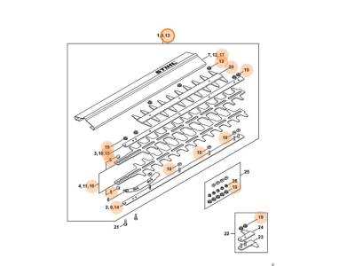
The outer casing and shielding elements are essential for ensuring the safety and functionality of any machinery. These components serve as barriers, safeguarding the internal mechanisms from external damage and environmental factors. Their design is crucial for maintaining the durability and operational efficiency of the equipment over time.
Durable materials are often employed for these protective coverings, providing resistance against wear, moisture, and physical impact. Additionally, the precise fitting of these parts is vital to prevent contaminants from interfering with the sensitive internal systems. The integration of ventilation features and accessibility for maintenance are also key aspects that contribute to the overall performance and longevity of the equipment.
Cutting Head and Blade Setup
Proper alignment and configuration of the cutting head and its components are crucial for optimal performance. Ensuring everything is securely installed and adjusted correctly guarantees smooth operation and efficient cutting. This process involves carefully positioning the key elements to achieve the best results while maintaining safety and reliability.
To assist in this setup, it’s important to follow a precise procedure, ensuring that each component is in the correct orientation. Regular inspection of wear and tear also plays a vital role in maintaining cutting efficiency.
| Component | Adjustment Details |
|---|---|
| Cutting Head | Ensure the cutting head is securely attached and aligned with the main frame. Adjust the height and angle to match the required cutting depth. |
| Blade | Check blade sharpness and alignment. Position it to ensure uniform cutting pressure across the width, and verify the tension is properly adjusted. |
| Blade Guard | Confirm the blade guard is firmly in place, providing safety without obstructing the cutting process. It should move freely without interference. |
| Drive Mechanism | Inspect the drive mechanism for smooth operation. Ensure all connections are tight and lubricated to reduce friction during use. |