Understanding the FS120 Component Diagram
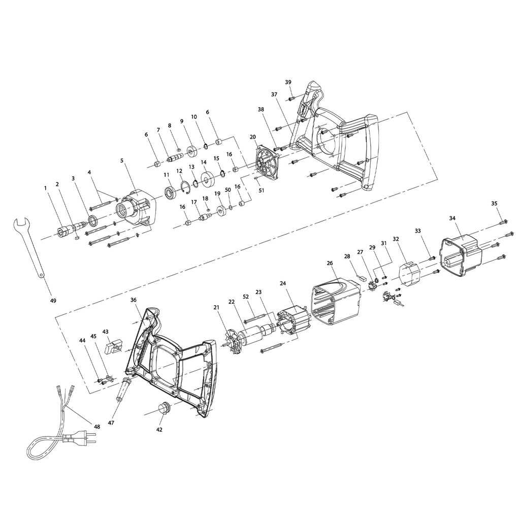
In the realm of mechanical systems, the intricate arrangements of various elements play a crucial role in ensuring optimal functionality and efficiency. Grasping the configuration of these individual components provides invaluable insights for both maintenance and enhancement. This section delves into the significance of comprehending these structures, paving the way for better performance and troubleshooting.
By exploring the interconnected nature of each element, users can develop a more profound understanding of how these systems operate cohesively. Familiarity with the organization of these constituents aids in recognizing potential issues and implementing effective solutions. Furthermore, this knowledge equips users with the tools necessary to engage in thoughtful modifications and upgrades.
In summary, a thorough awareness of the layout and relationships among these various components is essential for anyone involved in the care and improvement of mechanical systems. By fostering this understanding, one can enhance the overall efficiency and longevity of the equipment.
Key Components Overview
When maintaining or repairing complex systems, it’s crucial to understand the fundamental elements that ensure smooth operation. Each component plays a significant role, and identifying these elements can simplify troubleshooting and upkeep.
Primary Functional Elements
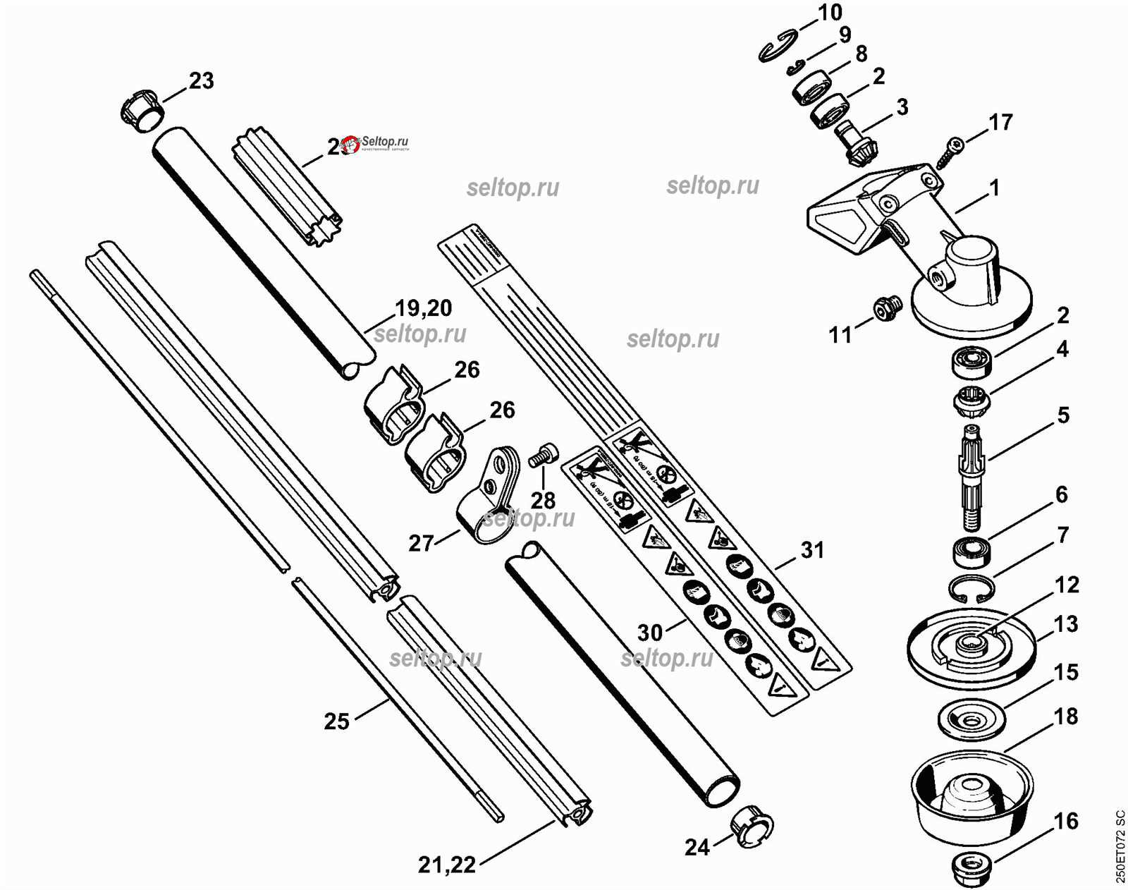
At the heart of the system lies a combination of mechanical and electrical elements. These elements work together to provide stability, precision, and power. Whether it’s the driving force behind movement or the components that ensure proper alignment, their roles are essential for optimal performance.
Supporting Mechanisms
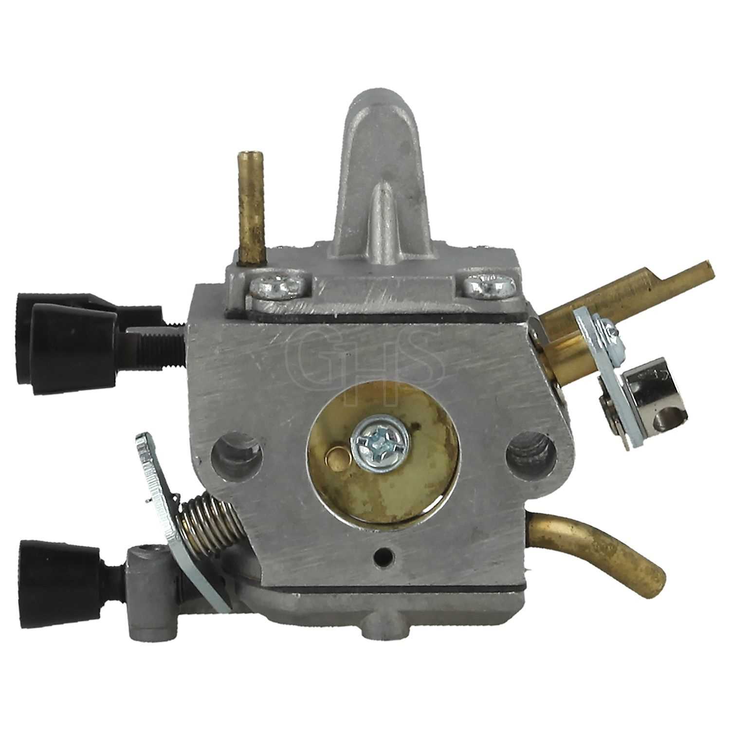
A variety of secondary mechanisms assist the primary elements. These mechanisms include stabilizers, regulators, and connectors, which contribute to both efficiency and durability. Ensuring these are functioning correctly is key to preventing wear and maintaining system longevity.
Importance of Accurate Diagrams
The precision of visual representations plays a crucial role in understanding complex mechanical systems. Without clear and correct schematics, identifying the right components or performing maintenance can become a challenge, leading to potential mistakes. Well-structured visuals help ensure that every element is correctly placed and easily interpreted, preventing costly errors.
Enhancing Understanding and Efficiency
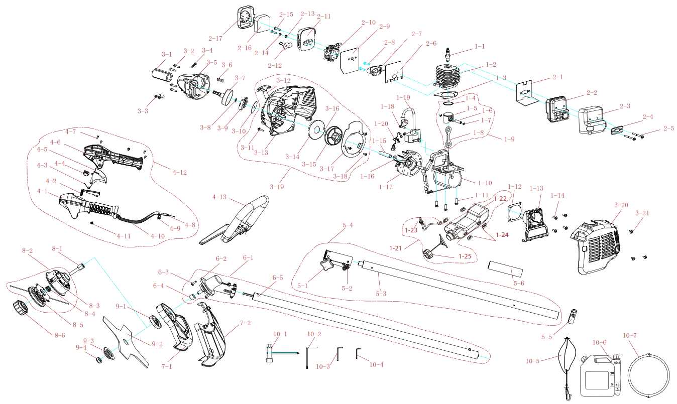
Accurate illustrations allow users to navigate intricate designs with ease. Whether it’s for assembly, troubleshooting, or repairs, these images serve as a reliable guide, minimizing confusion. By offering clear views of how elements connect, users can work more efficiently and avoid unnecessary delays.
Reducing Errors and Miscommunication
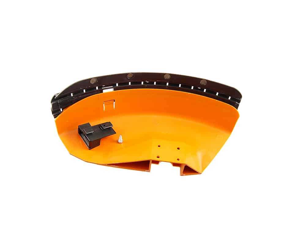
Clear visual aids help eliminate guesswork when identifying individual components or their placement. This reduces the chances of incorrect installations, ensuring that the entire system functions as intended. When used in professional settings, these visual guides also enhance communication between team members, ensuring everyone is on the same page.
Common Parts and Their Functions
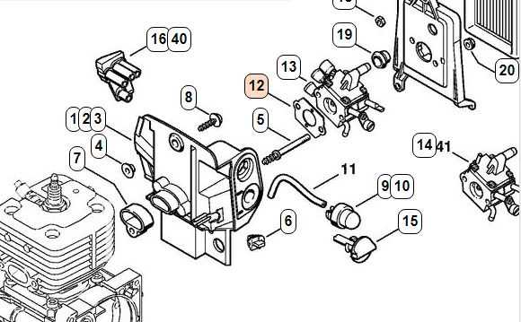
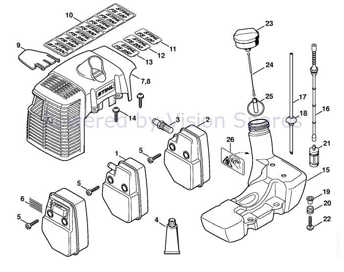
Understanding the components of any mechanical device is essential for both maintenance and troubleshooting. Each element plays a specific role, contributing to the overall efficiency and functionality of the system.
Engine Assembly: The central unit responsible for converting fuel into mechanical energy. This process powers the entire operation, ensuring smooth performance across various tasks.
Fuel Tank: A storage container designed to hold and supply fuel to the engine. Its capacity and construction are crucial for uninterrupted operation during extended periods.
Air Filter: Positioned to prevent dirt and debris from entering the internal systems, this component ensures clean airflow, prolonging the engine’s lifespan and maintaining optimal performance.
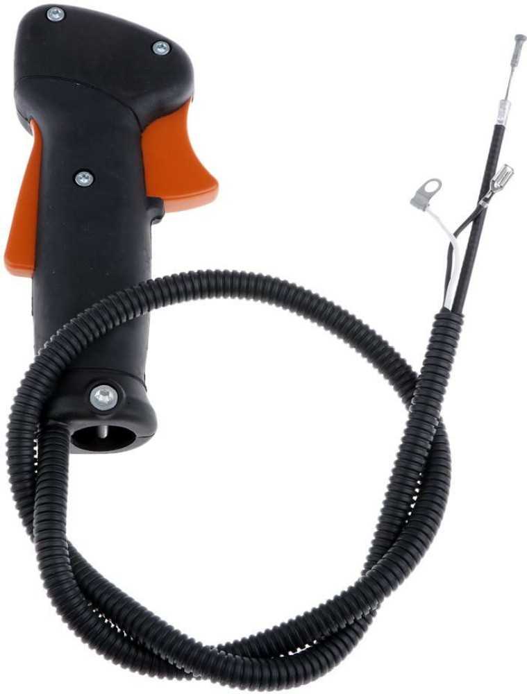
Throttle Control: This mechanism regulates the power output, allowing the user to adjust the speed and intensity of the machine based on the task at hand.
Exhaust System: A vital part that directs gases away from the engine, reducing noise and managing emissions for safe operation.
Visual Representation of Assembly
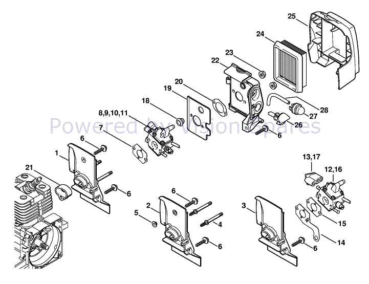
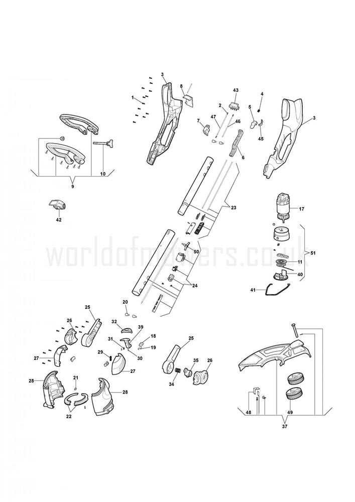
Understanding how different elements come together in a structure is crucial for ensuring proper functionality. The visual breakdown of each step in the process allows for easier identification of connections and ensures everything aligns correctly during reassembly. This approach simplifies both the learning process and practical application, helping avoid potential errors.
Key Components Overview
In any system, recognizing the primary elements is the first step toward smooth assembly. Each unit has its own role in the bigger picture, making it essential to familiarize yourself with their placement and function.
- Connectors and fasteners for securing all elements
- Core mechanisms responsible for operation
- Supporting structures that ensure stability
Step-by-Step Guide
Following a clear sequence is important to ensure efficient and correct assembly. Each phase must be approached methodically to prevent misalignment or damage.
- Identify the location of each component.
- Ensure all connectors are securely fastened before proceeding to the next section.
- Test the functionality after completing the assembly to verify accuracy.
Maintenance Tips for Longevity
Regular upkeep of mechanical systems ensures their extended life and optimal performance. Proper care minimizes wear, prevents malfunctions, and reduces the need for frequent repairs. Following key strategies can help maintain the system’s integrity and functionality over time.
Regular Cleaning
Dust and debris can accumulate, hindering efficient operation. A consistent cleaning schedule will help avoid blockages and ensure that components move freely. Use appropriate tools and avoid harsh chemicals that could cause damage.
Lubrication and Tightening
Maintaining moving parts with proper lubrication prevents friction and overheating. Check all fasteners regularly to ensure they are secure, as loose connections can lead to inefficient performance or even mechanical failure.
| Task | Frequency | Action | |||||||
|---|---|---|---|---|---|---|---|---|---|
| Cleaning | Monthly | Remove dust and debris | |||||||
| Lubrication | Quarterly | Apply grease to moving parts | |||||||
| Tightening | Annually |
| Misidentification Issue | Potential Consequence |
|---|---|
| Incorrect component assumed | May lead to incompatible replacements, causing malfunctions or operational delays. |
| Visual similarities between elements | Can result in the wrong part being installed, leading to system inefficiency or even damage. |
| Outdated reference materials | May cause confusion when older manuals or guides are used, resulting in the selection of inappropriate components. |
Resources for Parts Acquisition
When working on equipment maintenance or repairs, finding reliable sources for essential components is crucial. Acquiring high-quality elements not only ensures the longevity of your project but also optimizes overall performance.
Here are some key resources to explore when searching for necessary items:
- Manufacturer’s Website: Often, the original producer provides direct access to components, ensuring compatibility and authenticity.
- Authorized Distributors: Certified sellers guarantee genuine supplies and offer support for specific technical needs.
- Online Marketplaces: Platforms like e-commerce websites may offer competitive pricing, but caution is needed to verify sellers.
- Local Suppliers: Visiting physical stores can help confirm the quality of items and provide immediate assistance in finding suitable replacements.
- Specialized Forums: Engaging with online communities dedicated to your specific equipment can provide recommendations and trusted sources.
Using these resources, you can effectively source the necessary elements while ensuring compatibility and reliability.
Best Practices for Repair Procedures
Effective restoration methods are essential for maintaining the functionality and longevity of equipment. Adopting systematic approaches not only enhances the quality of repairs but also ensures safety and efficiency throughout the process.
Preparation and Assessment
- Gather necessary tools and materials before starting.
- Thoroughly inspect the equipment to identify all issues.
- Consult manuals or guides to understand the components involved.
Step-by-Step Repair Process
- Disassemble the unit carefully, keeping track of all components.
- Clean each part to remove dust, debris, or corrosion.
- Replace or repair damaged sections according to specifications.
- Reassemble the unit, ensuring all parts are securely fitted.
- Test the equipment to verify proper functionality after repairs.
