Understanding the Components of Hoover FH11300
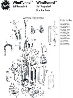
Cleaning devices today rely on a range of essential elements that contribute to their efficient operation. Each element plays a vital role in ensuring the machine functions smoothly, allowing users to achieve effective results with minimal effort. By exploring these integral features, we can better understand how such appliances are built for optimal performance.
One of the critical aspects of maintaining these devices is knowing how their inner elements are organized. Recognizing the function and placement of each component can help users with routine maintenance, ensuring the longevity of the machine. This section will highlight the most significant internal elements and their roles in a modern cleaner.
Familiarizing yourself with the detailed layout of these components allows for quick identification of potential issues. Whether you’re looking to replace a specific element or perform regular upkeep, having a clear understanding of the device’s structure will streamline the process, saving time and avoiding unnecessary complications.
Key Components Overview
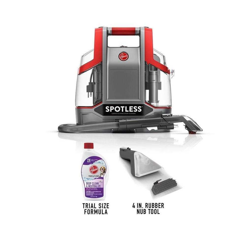
This section highlights the fundamental elements that are essential for the proper function and longevity of the cleaning device. Each element plays a significant role in ensuring optimal performance, and understanding their purpose is vital for maintenance and troubleshooting.
- Motor Assembly: The driving force behind the device, ensuring efficient suction and operation.
- Water Reservoir: A crucial container responsible for storing the liquid used in cleaning processes.
- Brush Roll: A rotating part designed to agitate and lift debris, making it easier to remove dirt from surfaces.
- Nozzle: Directs the flow of water and cleaning solution onto the surface, facilitating effective cleaning.
- Hose and Attachments: Provides flexibility in reaching tight spaces and ensures versatility in cleaning different areas.
Each of these components requires regular inspection to ensure the cleaning device continues to function at its best. Maintaining these elements will extend the unit’s life and enhance its cleaning capabilities.
Understanding the Brush Mechanism
The cleaning component responsible for effective debris removal relies on a rotating system designed to loosen dirt from surfaces. This feature ensures that the cleaning process is thorough by agitating particles embedded in carpets or upholstery, allowing for easier suction.
Central to this functionality is a cylindrical tool equipped with bristles. As it rotates, the bristles dislodge dirt and grime, lifting them from deep within the fabric. This action is crucial for maintaining cleanliness, particularly on high-traffic areas where dirt tends to accumulate over time.
The smooth operation of this component depends on a motorized drive system, which ensures consistent rotation and pressure. Regular maintenance, such as cleaning or replacing worn elements, will help preserve its efficiency and prolong the lifespan of the entire setup.
Exploring the Water Tank Assembly
The water tank assembly plays a crucial role in maintaining the proper functioning of any cleaning device, as it serves as the primary container for holding and distributing water during the cleaning process. Understanding how this section is constructed and operates can greatly aid in troubleshooting or replacing individual components.
Key Components of the Assembly
Several essential parts work together to ensure the efficient performance of the water tank system. From the seal that prevents leaks to the handle providing secure attachment, each piece is designed to contribute to a smooth cleaning experience.
| Component | Function | ||||||||||||||||||
|---|---|---|---|---|---|---|---|---|---|---|---|---|---|---|---|---|---|---|---|
| Tank Lid | Seals the container and prevents water from spilling during use. | ||||||||||||||||||
| Handle | Ensures easy transport and secure attachment to the main unit. | ||||||||||||||||||
| Seal | Prevents leakage and maintains proper water pressure inside the tank. | ||||||||||||||||||
| Release Valve | Controls the flow of water from the tank into the machine for
How the Motor System Operates
The motor system is the driving force behind the efficient functioning of many cleaning devices. This system converts electrical energy into mechanical motion, ensuring consistent and powerful operation. Understanding the motor’s structure and its processes helps to maintain optimal performance and identify potential issues.
The system’s components work together to transform energy into the force necessary for operation. Each part plays a crucial role in ensuring the device performs as intended. Identifying Electrical PartsWhen working with household cleaning devices, understanding the various components involved in the electrical system is essential. Each piece within the circuitry has a distinct function, ensuring the device operates smoothly and safely. Knowing how to distinguish these elements can prevent malfunctions and enhance the overall maintenance process. In most devices, you will find a combination of wires, connectors, and small modules that manage the flow of electricity. Identifying and familiarizing yourself with these features can help troubleshoot issues, whether you’re performing repairs or routine checks. The Function of the Cleaning NozzleThe cleaning nozzle serves as a crucial component in any floor care system, designed to optimize the removal of dirt and debris from various surfaces. Its primary purpose is to create a strong suction that effectively lifts particles, ensuring a thorough clean. Understanding the functionality of this element can enhance the overall cleaning experience and maintain the efficiency of the device. Design and ConstructionThe nozzle’s design significantly impacts its performance. Typically constructed from durable materials, it is engineered to withstand the rigors of regular use while providing flexibility in accessing different areas. The shape and size are tailored to facilitate maneuverability, allowing users to clean hard-to-reach spots without difficulty. Operational MechanismWhen in operation, the cleaning nozzle generates airflow that aids in the collection of dirt. This process involves several key aspects:
Connection Points and Hoses LayoutUnderstanding the arrangement of connection points and the configuration of hoses is essential for maintaining and troubleshooting cleaning devices. This section outlines how these components are interconnected and their roles in ensuring optimal performance. The layout typically includes multiple access points where hoses can be attached or detached, allowing for efficient operation. Each connection serves a specific purpose, such as facilitating suction or directing water flow. Properly managing these connections can significantly enhance the effectiveness of the appliance. Moreover, the orientation and length of the hoses play a critical role in the device’s functionality. Shorter hoses can improve suction power by minimizing air resistance, while longer hoses provide greater reach for cleaning larger areas. Familiarity with this layout allows users to navigate and utilize their equipment more effectively. Handle and Control Layout Explained
The configuration of the handle and control features plays a vital role in the overall functionality and ease of use of cleaning devices. Understanding the arrangement of these elements can significantly enhance the user experience, allowing for more efficient operation and maintenance. This section will delve into the various components and their intended purposes, ensuring users can maximize the benefits of their equipment. Key Components of the HandleThe handle is not merely a grip; it is an integral part of the machine’s operation. Below are the primary elements commonly found:
Control Panel FeaturesThe control panel features an array of buttons and indicators that facilitate the cleaning process. Here are some typical functions:
Maintaining the Power Cord SafelyEnsuring the longevity and functionality of electrical devices involves careful attention to their power cords. A well-maintained cord is essential for safe operation and can prevent potential hazards. Regular checks and proper handling techniques can significantly extend the lifespan of this vital component. Regular Inspection
Frequent examination of the power cord for any signs of wear or damage is crucial. Look for fraying, exposed wires, or discoloration. If any abnormalities are detected, it is important to address them immediately to prevent electrical hazards. Safe Storage PracticesWhen storing the device, ensure that the power cord is carefully coiled and not kinked or twisted. Avoid wrapping it too tightly, as this can cause stress on the wires. Additionally, keep the cord away from heat sources and sharp edges to prevent accidental damage. Properly Replacing Worn Out SealsMaintaining the efficiency of your cleaning device often hinges on the condition of its seals. Over time, these components may degrade due to regular use, resulting in diminished performance and potential leaks. Understanding the process of replacing these worn elements is essential for preserving the appliance’s functionality. Identifying Signs of Wear
Before proceeding with a replacement, it’s crucial to recognize the indicators that seals need attention. Common signs include visible cracks, brittleness, or a noticeable decrease in suction power. Regular inspections can help identify these issues early, preventing further damage and ensuring optimal operation. Steps for ReplacementTo effectively replace the worn seals, begin by gathering the necessary tools, such as a screwdriver and a soft cloth. Carefully disassemble the unit, taking note of the original placement of the seals. Remove the old seals gently and clean the surfaces to ensure a secure fit for the new components. Finally, install the new seals in their designated locations, reassemble the device, and conduct a test run to confirm that the issue has been resolved. |
