Overview of Hunter TCX535 Parts Diagram
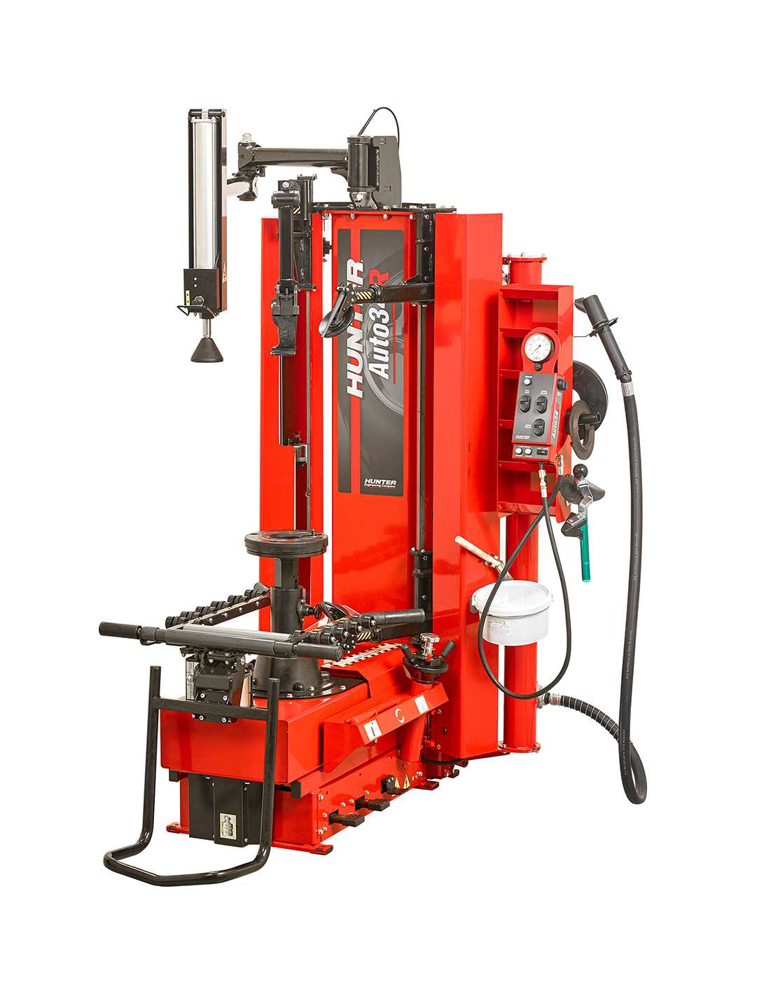
The functionality and efficiency of any advanced mechanical structure depend on the precise arrangement and interaction of its internal elements. When it comes to ensuring smooth operation, having a clear overview of these interconnected parts is crucial. This section provides a detailed examination of the essential elements that contribute to the overall performance of the system.
By exploring the main building blocks, users can gain insights into how each section works together to maintain optimal functionality. From small mechanisms to larger assemblies, understanding these components can simplify both maintenance and potential upgrades.
This guide is designed to help identify and familiarize oneself with various internal elements, ensuring the user is well-equipped for any necessary adjustments or replacements in the future.
Understanding the Hunter TCX535 Structure
The inner configuration of this specific model follows a well-thought-out design that enhances both functionality and durability. Every component is positioned to work seamlessly, ensuring smooth operation during every use. The overall build is not only robust but also strategically engineered to simplify maintenance and extend the lifespan of the machine. This section will explore how the various elements are arranged and how they contribute to the performance of the device.
At the core of the structure lies a system of interconnected elements that collaborate to deliver precise functionality. These elements are positioned in such a way as to maximize efficiency while minimizing the chances of malfunction. Whether it’s the foundation providing stability or the internal mechanisms handling more delicate tasks, each part serves a critical role in the overall operation of the equipment.
Key Components Overview
This section provides a detailed examination of the essential elements that make up the equipment. Each component plays a crucial role in ensuring the device operates smoothly and efficiently. Understanding the function and arrangement of these parts is vital for maintenance and troubleshooting.
- Main Frame: The structural foundation that supports all other elements, ensuring stability during operation.
- Control Unit: The central hub where settings are adjusted and monitored for optimal performance.
- Rotating Mechanism: Responsible for handling and movement, allowing precise and controlled motion.
- Hydraulic System: Delivers power to various parts of the equipment, enabling smooth and efficient operation.
- Sensor Array: A network of sensors that monitor critical parameters, ensuring safety and accuracy during use.
Each of these components must work in harmony to achieve the desired outcome, with routine inspections and maintenance ensuring longevity and performance.
Internal Mechanisms and Their Functions
The inner structure of the equipment is comprised of several essential systems that work together to ensure smooth and reliable operation. Each component plays a specific role, contributing to the overall efficiency and performance of the device. Understanding these mechanisms allows for better maintenance and troubleshooting, ensuring a longer lifespan and optimal functionality.
Key Functional Systems
- Drive Unit: This section is responsible for converting energy into the necessary force required for operation. It ensures movement and coordination between various mechanical elements.
- Control Circuitry: The core of the operational logic, this system manages the commands and feedback loops, allowing for precise adjustments and accurate responses during use.
- Power Transmission: Connecting the source of energy to the working parts, this mechanism distributes power efficiently across all operational areas.
Additional Functional Elements
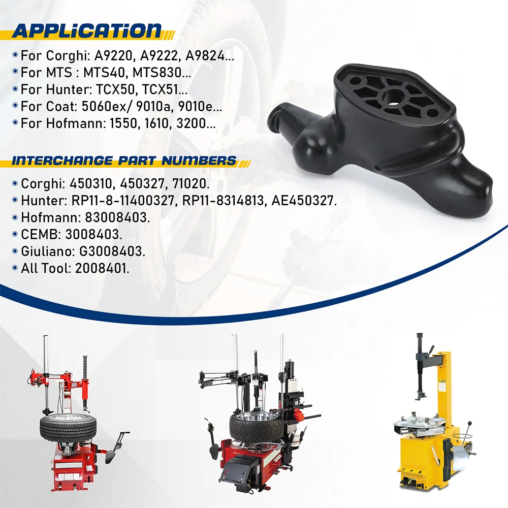
- Synchronization Gears: These gears maintain alignment between different moving parts, ensuring that the timing and coordination remain precise.
- Safety Mechanisms: Integrated protective systems prevent overloading and minimize potential damage during operation, enhancing reliability.
Exploring the Hydraulic System
The hydraulic system is a crucial component responsible for enabling precise control and smooth operations. By utilizing fluid power, it allows for the efficient transfer of energy and movement in various mechanical processes. Understanding its structure and functioning is essential to ensure optimal performance and troubleshooting.
- Main Components: The hydraulic system is composed of several key elements that work in unison to generate and manage fluid pressure, ensuring consistent power delivery.
- Fluid Power Transmission: Pressurized fluid is used to transfer force between different parts of the system, allowing for controlled movement and operation of mechanical functions.
- Flow Control: Various valves regulate the flow and direction of the hydraulic fluid, ensuring the system responds accurately to input commands.
- Pumps: These generate the necessary fluid pressure, driving the system by circulating hydraulic fluid through the network.
- Cylinders and Motors: These convert hydraulic pressure into mechanical energy, providing the force required for lifting, rotating, or other tasks.
- Filtration: Cleanliness is critical in a hydraulic setup, so filters are installed to prevent contaminants from disrupting the flow or damaging components.
Maintaining the hydraulic system in top condition involves regular checks of fluid levels, seals, and pressure readings. Keeping these in balance ensures longevity and reliability in its performance.
Electrical Wiring and Connections
Proper setup of the wiring system is crucial for the safe and efficient operation of your equipment. Ensuring correct connections and maintaining all electrical components can prevent common malfunctions and extend the system’s lifespan. Below, we’ll cover the necessary steps and precautions for handling the wiring connections in a safe and organized manner.
Safety Precautions
- Always disconnect the power source before working on any wiring connections.
- Use insulated tools to avoid accidental short circuits.
- Verify all connections are secure to prevent loose wires from causing interruptions or overheating.
Wiring Layout
The wiring system should follow a structured layout to avoid confusion and ensure smooth operation. Organize the wiring by grouping related circuits together and clearly marking each one. Below is a basic outline of how to manage the connections:
- Identify the power input terminals and connect the main power supply.
- Arrange the signal cables according to their designated functions.
- Check the grounding wires to ensure a stable and secure connection.
By following these guidelines, the electrical setup will remain stable and functional, ensuring optimal performance over time.
Main Operating Controls and Settings
The functionality of a device relies heavily on its primary operating mechanisms and adjustable configurations. Understanding these elements is essential for achieving optimal performance and ensuring efficient use. This section explores the various controls and settings that influence operation, providing insight into their significance and application.
At the forefront of these controls are the temperature adjustments, which allow users to regulate the heat output according to specific requirements. Typically, this feature includes a range of settings, from low to high, enabling precise management of the environment.
Another critical component is the timing control, which governs the duration of operation. This feature is particularly beneficial for scheduling use, promoting energy efficiency and convenience. By customizing the timing, users can ensure that the device operates only when needed, reducing unnecessary energy consumption.
Additionally, the mode selection function offers versatility, allowing users to switch between different operational modes tailored to various tasks. Whether it’s for standard performance or specialized functions, this feature enhances adaptability, ensuring the device meets diverse needs.
Lastly, it is vital to familiarize oneself with the safety features integrated into the controls. These mechanisms are designed to prevent malfunctions and protect users, making it crucial to understand how to engage and disengage them as necessary.
Identifying External Frame Parts
Understanding the components of an external structure is essential for effective maintenance and repair. This section aims to guide users through the identification of various elements that make up the frame, emphasizing their roles and significance. Familiarity with these components can enhance troubleshooting efforts and ensure optimal functionality.
Key Components to Recognize
- Support Beams: These are the primary structural elements that provide stability and strength to the entire framework.
- Connectors: Fasteners or joints that link various sections of the frame together, ensuring a secure assembly.
- Corners: Reinforced areas where two or more beams meet, crucial for maintaining overall integrity.
- Brackets: Additional supports that help distribute loads and enhance the stability of the frame.
- Cover Plates: Protective elements that shield the underlying components from environmental factors.
Importance of Proper Identification
Accurate recognition of each element is vital for successful repair procedures. Understanding the role of each part helps in diagnosing issues effectively and facilitates informed decisions regarding replacement or upgrades. Regular inspections can prevent minor concerns from escalating into significant problems, ensuring longevity and reliability.
Brake and Clutch System Components
The efficiency and safety of any vehicle greatly depend on its braking and clutch mechanisms. These systems play a crucial role in ensuring smooth operation, allowing for effective speed regulation and control. Understanding the various elements involved in these systems is essential for maintenance and performance optimization.
Key Components of the Brake System
- Brake Pads: These are essential for creating friction against the rotors, facilitating effective stopping power.
- Brake Rotors: These components are integral in dissipating heat generated during braking, ensuring consistent performance.
- Calipers: Responsible for housing the brake pads and applying pressure to the rotors, calipers are vital for the braking process.
- Brake Lines: These hydraulic lines transmit fluid from the master cylinder to the calipers, enabling the braking action.
- Master Cylinder: This component generates hydraulic pressure to activate the brakes when the pedal is pressed.
Essential Elements of the Clutch System
- Clutch Disc: The friction material that engages and disengages the engine from the transmission, allowing for smooth gear changes.
- Pressure Plate: This component applies pressure to the clutch disc, ensuring proper engagement with the flywheel.
- Release Bearing: Also known as the throw-out bearing, it facilitates the disengagement of the clutch when the pedal is pressed.
- Flywheel: This part serves as a connecting point between the engine and the transmission, playing a crucial role in power transfer.
- Clutch Pedal: The interface for the driver, allowing for the manual engagement and disengagement of the clutch.
Wheel Mounting Mechanism Breakdown
The wheel mounting mechanism plays a crucial role in ensuring the stability and performance of any equipment. Understanding the components and their interactions is essential for proper maintenance and troubleshooting. This section will delve into the various elements involved in the assembly, providing insights into their functions and significance.
Key Components
Several key components make up the wheel mounting assembly. Each part serves a specific purpose, contributing to the overall functionality of the mechanism. Below is a table summarizing these essential elements:
| Component | Description |
|---|---|
| Hub | The central part that connects the wheel to the axle. |
| Spindle | A rod that supports the wheel and allows for rotation. |
| Bearing | Facilitates smooth rotation and reduces friction between moving parts. |
| Fasteners | Secure the components together, ensuring stability and safety during operation. |
Functionality Overview
The interaction between these components is vital for optimal performance. The hub attaches to the spindle, allowing the wheel to spin freely. Bearings minimize friction, which enhances efficiency and prolongs the lifespan of the assembly. Proper fastening ensures that all parts remain securely connected, preventing potential malfunctions.
Maintenance Areas and Access Points
Proper upkeep of machinery involves understanding the critical zones and entry points for service tasks. Familiarity with these locations ensures efficient inspection, repairs, and part replacements, ultimately prolonging the equipment’s lifespan and enhancing performance. Accessing the right areas facilitates smoother operations, reducing downtime during maintenance activities.
Key Zones for Upkeep
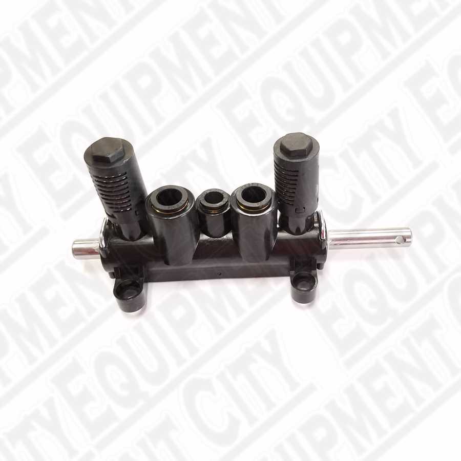
Identifying the essential regions for routine servicing is crucial. These zones typically include areas for fluid checks, filter replacements, and component inspections. By concentrating on these sections, operators can efficiently address potential issues before they escalate into significant problems.
Access Points for Service
Various entry points are designed to allow easy access to internal components. These points are strategically placed to simplify maintenance tasks, ensuring that users can reach critical parts without extensive disassembly. Regularly checking these access points can enhance overall reliability and efficiency.
Wearable Parts and Replacement Guide
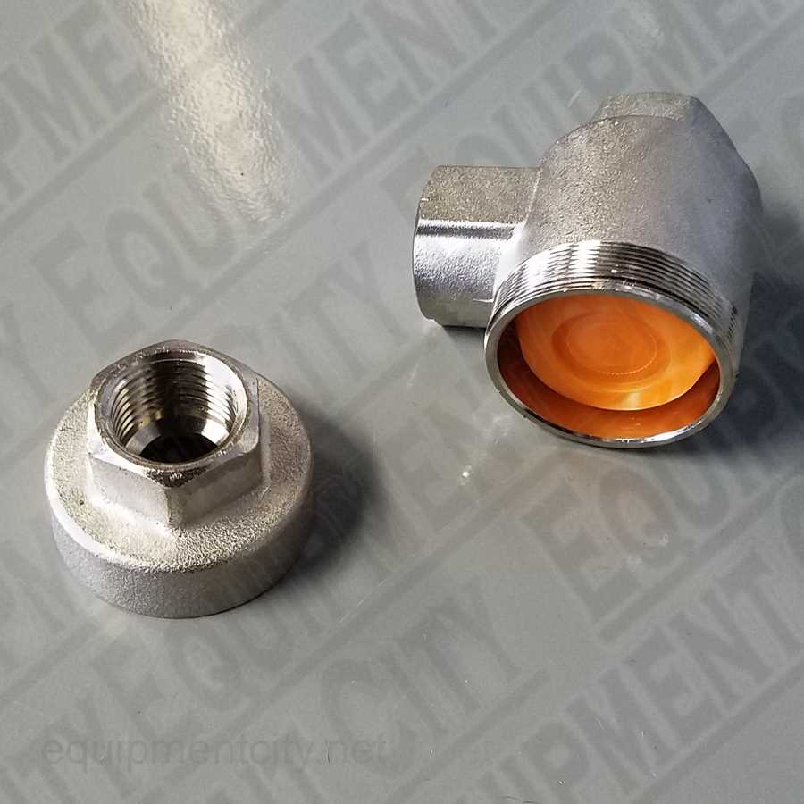
Maintaining the efficiency of your equipment involves understanding its various components that undergo regular wear and tear. This section provides an overview of essential elements that require periodic attention and replacement, ensuring optimal performance and longevity.
Key components that may need replacement include:
- Seals and Gaskets
- Filters
- Belts and Hoses
- Brake Pads
- Bearings
It’s crucial to identify signs of wear on these components to prevent more significant issues in the future. Regular inspections can help in timely replacements, reducing downtime and enhancing overall functionality.
When considering replacements, follow these guidelines:
- Consult the user manual for specifications on the required components.
- Choose high-quality replacements to maintain performance standards.
- Document any changes for future reference and maintenance records.
By keeping track of wearable elements and addressing replacements proactively, you can ensure that your equipment remains in peak condition and continues to meet your operational needs effectively.
Troubleshooting Common Component Issues
Identifying and resolving problems with equipment components is essential for maintaining optimal performance. This section outlines common issues encountered in various mechanisms and offers practical solutions to restore functionality.
When dealing with malfunctioning parts, it is crucial to follow a systematic approach to diagnosis. Below is a table highlighting typical issues, their potential causes, and recommended troubleshooting steps.
| Issue | Possible Causes | Troubleshooting Steps |
|---|---|---|
| Failure to Start | Power supply issues, faulty wiring, component malfunction | Check power connections, inspect wiring for damage, test components for functionality |
| Inconsistent Performance | Blockages, worn parts, improper settings | Clear any obstructions, replace worn components, verify settings are correct |
| Excessive Noise | Loose parts, lack of lubrication, misalignment | Tighten loose components, apply appropriate lubricant, check alignment |
| Overheating | Insufficient airflow, damaged components, overload | Ensure adequate ventilation, inspect for damaged parts, reduce load if necessary |
By following these guidelines and addressing the specified concerns, users can effectively troubleshoot and resolve common problems, ensuring reliable operation of their equipment.
Lubrication Points and Fluid Systems
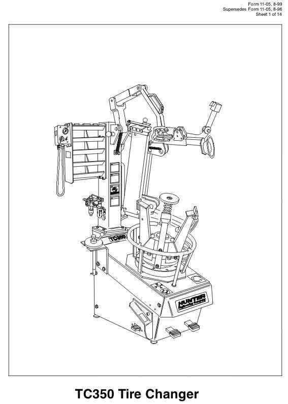
Effective maintenance of machinery heavily relies on understanding the critical areas for lubrication and the various fluid systems in place. Ensuring that all necessary components are adequately lubricated promotes longevity and efficiency, while also reducing the likelihood of mechanical failures. Identifying and managing these points is essential for optimal performance.
Key Lubrication Areas
- Bearings: Regularly lubricate to minimize friction and wear.
- Gears: Use appropriate grease to ensure smooth operation.
- Pivots and Joints: Apply lubricant to enhance mobility and prevent rust.
- Chains: Maintain lubrication to avoid corrosion and ensure efficiency.
Fluid Systems Overview
Understanding the various fluid systems that support machinery is crucial. These systems not only aid in lubrication but also play a significant role in cooling and transferring energy. Regular checks and maintenance are necessary to keep these systems functioning effectively.
- Hydraulic System: Ensures smooth operation of various components through fluid pressure.
- Cooling System: Maintains optimal operating temperatures by circulating coolant fluid.
- Fuel System: Delivers fuel to the engine while ensuring clean operation.
Maintaining these lubrication points and fluid systems is vital for the overall health of machinery. Regular inspections and timely interventions will lead to enhanced performance and extended service life.