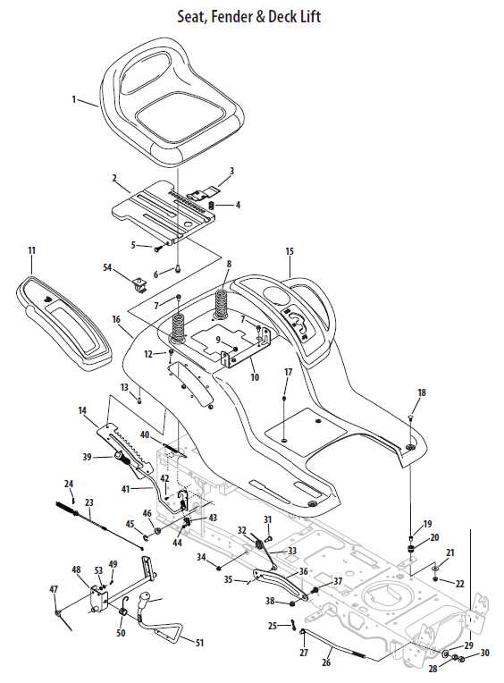
Overview of Ltx1040 Parts Diagram and Components
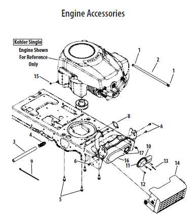
ltx1040 parts diagram

Understanding the internal structure and layout of various elements in a machine is crucial for ensuring smooth operation and timely maintenance. A detailed visual representation of these elements can significantly simplify the process of identifying the correct item for replacement or repair.

Efficient planning when it comes to upkeep can save both time and resources. By focusing on each component and its placement, users can better navigate the overall system, enabling faster solutions to technical issues.

Whether you are a professional mechanic or handling routine checks, having access to a structured and detailed overview of the system’s layout will improve your ability to address issues with precision.

Understanding the Mower Structure

The internal composition of the lawn tractor is designed to ensure efficient operation across various terrains. This section provides an overview of its key components and how they interact to deliver smooth performance during use. By examining the arrangement of its mechanical and functional systems, users can gain insight into the machine’s overall design.

Main Components of the Cutting System

The cutting mechanism plays a crucial role in maintaining lawns. It includes several key elements that work together to ensure precise trimming. Each part is strategically placed to contribute to the effectiveness of the machine, from the blades to the support elements. This system enables efficient grass cutting while maintaining durability.

Transmission and Movement

The propulsion system is another vital aspect, helping the machine move seamlessly over various surfaces. The connection between the engine and the drive system allows for a steady pace while minimizing strain on the motor. This ensures both stability and ease of control, making the equipment reliable for longer periods of operation.

Key Components Breakdown of the Ltx1040

In this section, we will explore the essential elements that make up this particular model, focusing on its crucial assemblies and their roles in overall functionality. These parts work together to ensure smooth operation and efficient performance.

  • Engine Assembly: The core power source, responsible for driving the entire mechanism, ensuring a consistent and powerful output.
  • Transmission System: This component manages the transfer of power from the engine to the wheels, allowing for seamless movement and control.
  • Steering Mechanism: Provides precise control, allowing the user to easily navigate and maneuver the machine in various directions.
  • Cutting Deck: The cutting system that trims and maintains the grass, delivering a clean and professional finish to the lawn.
  • Drive Wheels: These enable movement, ensuring proper traction on different terrains, contributing to smooth operation.
  • Control Panel: Houses all the essential controls, giving the user easy

    Blade Assembly and Maintenance Overview

    Proper upkeep and installation of the cutting mechanism are crucial for the optimal performance of your equipment. Ensuring that all components are correctly aligned and regularly serviced will extend the lifespan of the device and improve its overall efficiency.

    The assembly process involves attaching the sharpened edge and securing it with the necessary fasteners. Regular checks and routine servicing will help maintain peak functionality and reduce the risk of malfunctions.

    • Ensure that all bolts and fasteners are tightened appropriately.
    • Check the sharpness of the blades frequently and sharpen when necessary.
    • Lubricate moving parts to minimize friction and wear.
    • Replace worn or damaged elements to avoid further issues.

    Following these maintenance steps will ensure that your equipment operates smoothly and efficiently.

    Engine System Parts and Functions

    The engine system consists of various components that work together to ensure the machine runs efficiently. Understanding the role of each element helps in maintaining the system and ensuring long-lasting performance.

    Key Components of the Engine

    • Cylinder: The core of the engine, where fuel is burned to create power.
    • Spark Plug: Initiates combustion by igniting the air-fuel mixture inside the cylinder.
    • Fuel Pump: Supplies the necessary fuel to the engine under pressure for combustion.
    • Exhaust Valve: Releases exhaust gases generated during combustion out of the system.

    Function of Each Element

    Each element in the engine system has a specific role. The cylinder converts fuel into mechanical energy, while the spark plug triggers the ignition process. The fuel pump ensures that fuel reaches the engine, and the exhaust valve controls the flow of exhaust gases out of the engine, maintaining efficiency and performance.

    Deck Belt and Pulley Configuration

    The proper setup of the deck belt and pulley system is essential for smooth and efficient operation of the cutting deck. Ensuring the alignment and correct positioning of the components will prevent wear and improve performance over time. This section will explain how the belt wraps around the pulleys and how the system drives the blades.

    Key Components of the System

    The configuration consists of several pulleys and tensioners that guide the belt along its path. Each pulley plays a role in maintaining tension and ensuring the smooth rotation of the cutting blades. Regular inspection of these elements is recommended to ensure that the system functions properly.

    Maintaining the Configuration

    Keeping the belt in optimal condition is vital for the longevity of the entire system. Proper tension adjustment and replacing worn components as needed will help maintain the functionality of the belt and pulley arrangement. Check for signs of wear regularly to avoid unexpected issues.

    Transmission Mechanism in the Ltx1040

    The transmission system of this specific model plays a crucial role in ensuring efficient power transfer and optimal performance. It consists of various components working in harmony to facilitate the movement and control of the vehicle. Understanding the intricacies of this mechanism is essential for maintaining functionality and addressing potential issues that may arise.

    At the heart of the transmission system is the gearbox, which is responsible for adjusting torque and speed. This component allows the engine to operate within its optimal range while providing the necessary force to propel the vehicle. Additionally, the synchronization of gears ensures smooth transitions during operation, enhancing the overall driving experience.

    Another vital element is the clutch assembly, which enables the driver to engage or disengage the engine from the transmission. This function is essential for starting, stopping, and changing gears seamlessly. A well-maintained clutch system contributes to the longevity of the entire mechanism, reducing wear and tear on components.

    Moreover, the drive shafts serve as conduits for delivering power to the wheels. Their design is critical in maintaining balance and stability, especially during acceleration and deceleration. Ensuring that these shafts are free from damage and adequately lubricated is key to preserving performance and preventing mechanical failures.

    In conclusion, a thorough understanding of the transmission system, including its various components and their functions, is paramount for effective maintenance and operation. Regular inspections and timely repairs can significantly enhance the durability and efficiency of the entire mechanism.

    Steering System and Linkage Components

    The steering mechanism and associated linkage elements are crucial for ensuring smooth maneuverability and control of the vehicle. This assembly plays a significant role in translating the driver’s inputs into precise movements, allowing for responsive handling and stability during operation.

    Key Elements of the Steering Mechanism

    ltx1040 parts diagram

    At the core of the steering system lies the steering wheel, which is connected to the steering column. This setup converts rotational movement into lateral motion through a series of components. The rack and pinion system is often employed, providing efficient response and a direct connection between the wheel and the wheels of the vehicle.

    Linkage Components and Their Functions

    Linkage components serve as the vital connectors within the steering assembly. These elements include tie rods, control arms, and various joints that work together to transmit force and maintain alignment. Proper maintenance and inspection of these components are essential to ensure optimal performance and safety.

    Electrical Connections and Wiring Layout

    The proper arrangement of electrical links and the configuration of wiring play a crucial role in ensuring the efficient operation of machinery. Understanding how these components interact is essential for troubleshooting and maintenance tasks. A well-structured wiring setup not only enhances functionality but also promotes safety within the system.

    Connections are often established using various types of terminals, connectors, and plugs, which facilitate reliable communication between different electrical elements. Each component should be carefully chosen to match the specific requirements of the application, ensuring compatibility and minimizing the risk of failure.

    Wiring layout involves the strategic positioning of cables and wires to avoid interference and optimize performance. Proper insulation and routing techniques are vital to prevent short circuits and electrical hazards. A clear and organized wiring scheme also simplifies future modifications and repairs, making it easier to identify and rectify potential issues.

    Fuel System Diagram and Specifications

    This section provides an overview of the fuel delivery system, focusing on its layout and technical details. Understanding the components involved is crucial for effective maintenance and troubleshooting of the equipment.

    The fuel system is responsible for storing, filtering, and delivering fuel to the engine. Its efficiency directly impacts performance and reliability. Below is a table that outlines the main components along with their specifications:

Component Function
Component Description Specifications
Fuel Tank Reservoir for storing fuel. Capacity: 10 gallons
Fuel Pump Pumps fuel from the tank to the engine. Flow Rate: 30 GPH
Fuel Filter Removes impurities from the fuel. Micron Rating: 10 microns
Fuel Injector Atomizes fuel for efficient combustion. Type: Electronic
Fuel Lines Transport fuel between components. Material: Reinforced rubber

Understanding the layout and specifications of each element helps ensure the fuel system operates efficiently, providing optimal performance.

Tire and Wheel Assembly Details

The assembly of tires and wheels is a crucial component in ensuring optimal performance and safety in various machinery. Understanding the structure and characteristics of this assembly helps in maintaining and troubleshooting issues effectively.

Key components involved in the tire and wheel assembly include:

  • Tires: The outer part that provides traction and supports the load.
  • Rims: The metal framework that holds the tire in place.
  • Valves: Essential for maintaining air pressure within the tire.
  • Hub: The central part that connects the wheel to the axle.
  • Bearings: Allow smooth rotation of the wheel.

Proper assembly ensures that all components fit securely and function together harmoniously. Regular inspections of the tire and wheel assembly can prevent performance issues and extend the lifespan of the machinery.

When addressing maintenance, consider the following aspects:

  1. Check for wear and tear on tires.
  2. Inspect rims for damage or corrosion.
  3. Ensure valves are functioning correctly to avoid air leaks.
  4. Verify the tightness of bolts connecting the wheel to the hub.
  5. Lubricate bearings to ensure smooth movement.

Understanding these details enhances the overall efficiency and reliability of the equipment, ensuring safe and effective operation.

Brake and Safety Mechanism Explained

The braking and safety systems play a vital role in ensuring the smooth and secure operation of machinery. These components work together to provide effective stopping power while minimizing the risk of accidents. Understanding how these mechanisms function can help users maintain and operate their equipment more safely.

There are several key elements involved in the braking and safety system:

  • Braking System: This component is responsible for slowing down or stopping the machinery. It typically consists of a series of parts that work in tandem to create friction and bring the machine to a halt.
  • Safety Features: Various safety measures are integrated to prevent unintended movement or accidents. These may include automatic shut-off switches and emergency brakes that activate in critical situations.
  • Control Mechanisms: Operators can manage the braking system through various controls, ensuring precise handling and responsiveness during operation.

To ensure optimal performance, regular maintenance of the braking and safety systems is essential. Users should routinely check for wear and tear on components and address any issues promptly. This proactive approach not only enhances safety but also extends the lifespan of the machinery.

In summary, understanding the intricacies of the braking and safety systems is crucial for effective operation. By familiarizing oneself with these components, users can enhance their safety and the overall functionality of their equipment.

Chassis and Frame Structure Design

The design of the chassis and frame structure is fundamental to ensuring stability and durability in any vehicle. A well-engineered framework not only supports the overall weight but also influences handling and performance. Understanding the intricacies of these components is crucial for optimizing the vehicle’s functionality and safety.

Various elements contribute to the effectiveness of the chassis and frame structure, including materials used, design geometry, and load distribution. The integration of advanced engineering principles allows for the development of lightweight yet robust structures that can withstand various operational stresses.

Component Function Material Used
Main Frame Supports the vehicle’s body and components Steel or Aluminum
Cross Members Enhances rigidity and structural integrity High-Strength Steel
Suspension Mounts Connects suspension systems to the frame Cast Iron or Steel
Chassis Brackets Facilitates attachment of various components Steel