Understanding Massey Ferguson 255 Parts Diagrams for Efficient Maintenance
The maintenance and repair of agricultural machinery require a clear understanding of the intricate systems that power it. Having access to detailed information about the inner workings of such equipment is essential for both efficiency and longevity. This section provides valuable insights into the various mechanisms and structures involved in these machines, helping you grasp the fundamental principles behind their operation.
Exploring the detailed layouts of different mechanical systems allows for a better understanding of how individual elements interact. This knowledge is crucial for addressing common technical challenges and ensuring the smooth operation of the equipment over time. By examining the organization of these systems, you can better identify and troubleshoot potential issues.
Understanding the connections between different components also aids in proper upkeep and ensures that everything runs as intended. This guide will walk you through the essential configurations and arrangements, offering a practical resource for anyone seeking to maintain their agricultural equipment in top condition.
The following section provides a comprehensive look at the essential elements of this agricultural machine. Understanding these individual units is crucial for ensuring smooth operation and maintenance. By breaking down the various sections, we aim to offer a clear view of how each element functions within the larger system, allowing for easier troubleshooting and upkeep.
- Engine Assembly
- Transmission System
- Hydraulic Mechanism
- Electrical Wiring and Components
- Steering and Control Elements
Each of these sections plays a vital role in the overall performance of the equipment. Below, we will explore each of these areas in detail to offer further insights into their operation and importance.
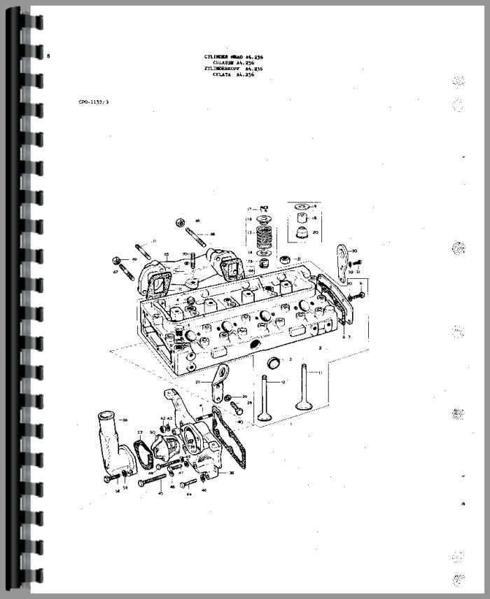
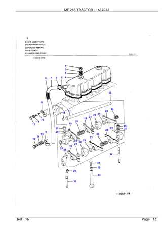
Engine System Parts and Layout
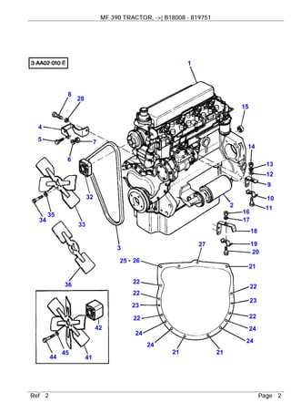
The engine system is a complex arrangement of interconnected components that work together to ensure optimal performance. Understanding the structure and positioning of these elements is essential for efficient maintenance and troubleshooting. This section explores the various components that make up the core of the engine system, focusing on their arrangement and functions.
At the heart of the system is the combustion area, where fuel and air interact to generate power. Surrounding this are numerous auxiliary elements responsible for regulating temperature, pressure, and fuel flow. Each piece plays a critical role in keeping the system running smoothly and efficiently, from the cooling mechanisms to the fuel delivery setup.
The overall layout is designed to optimize accessibility for routine inspections and adjustments, allowing for a streamlined maintenance process. By familiarizing yourself with the key sections and their functions, you can better navigate the system and address any operational challenges that may arise.
Transmission Components Breakdown
The transmission system is responsible for ensuring that power generated by the engine is effectively transferred to the wheels. By converting engine output into usable energy, the system allows for smooth operation and control across various speeds and conditions. Understanding how each part of the transmission works together can help identify potential issues and maintain peak performance.
Key elements within the transmission include gears, shafts, and clutches, each serving a distinct function. These components work in unison to regulate power distribution and adapt to different mechanical demands, enabling efficient control and operation of the vehicle. Each piece plays a critical role in managing torque and ensuring seamless gear shifting for optimal efficiency.
Hydraulic System Assembly Guide
The hydraulic system is an essential component that ensures the smooth operation of various machinery by transferring power through fluid pressure. Proper assembly of this system guarantees reliable performance and extends the life of the equipment. This guide provides a clear overview of the necessary steps to assemble the hydraulic mechanism safely and efficiently.
Main Components and Connections
Begin by identifying the core elements of the system, including the pump, valves, and cylinders. Each component must be securely connected using the appropriate fittings to ensure leak-free operation. When attaching hoses, make sure to check for compatibility with pressure ratings and confirm that all seals are in place. Regular inspections of these connections will help prevent any potential malfunctions during use.
Testing and Final Adjustments
After completing the assembly, it’s crucial to test the system under controlled conditions. Gradually pressurize the fluid and observe the movement of each part to ensure smooth operation. If any irregularities arise,
Electrical Wiring Diagram Overview
Understanding the flow of electricity in a machine is crucial for ensuring its smooth and safe operation. Electrical layouts provide a clear visual representation of the connections between various components, helping users troubleshoot and maintain the system. This overview will highlight key elements and their relationships, making it easier to identify potential issues or optimize the setup for better performance.
| Component | Function | ||||||||||||||||||||||||||||||||||||||||||||
|---|---|---|---|---|---|---|---|---|---|---|---|---|---|---|---|---|---|---|---|---|---|---|---|---|---|---|---|---|---|---|---|---|---|---|---|---|---|---|---|---|---|---|---|---|---|
| Battery | Supplies power to the entire electrical system, ensuring that all parts receive the necessary energy to function. | ||||||||||||||||||||||||||||||||||||||||||||
| Alternator | Converts mechanical energy into electrical power to recharge the battery and supply energy to electrical systems. | ||||||||||||||||||||||||||||||||||||||||||||
F
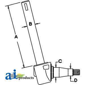
Front Axle and Steering PartsThe front axle and steering assembly play a crucial role in ensuring the stability and maneuverability of agricultural machinery. This section explores the essential components that facilitate smooth handling and support the weight of the vehicle. Key elements of this system include the axle housing, which provides structural integrity, and the spindles, which allow for rotation and directional control. Additionally, tie rods connect the steering gear to the wheels, translating driver inputs into movement. The inclusion of bushings and bearings minimizes friction, enhancing performance and longevity. Understanding the function of these components is vital for maintenance and troubleshooting. Regular inspection and timely replacement of worn elements can significantly improve operational efficiency and safety during use. Brake System Diagram and Details
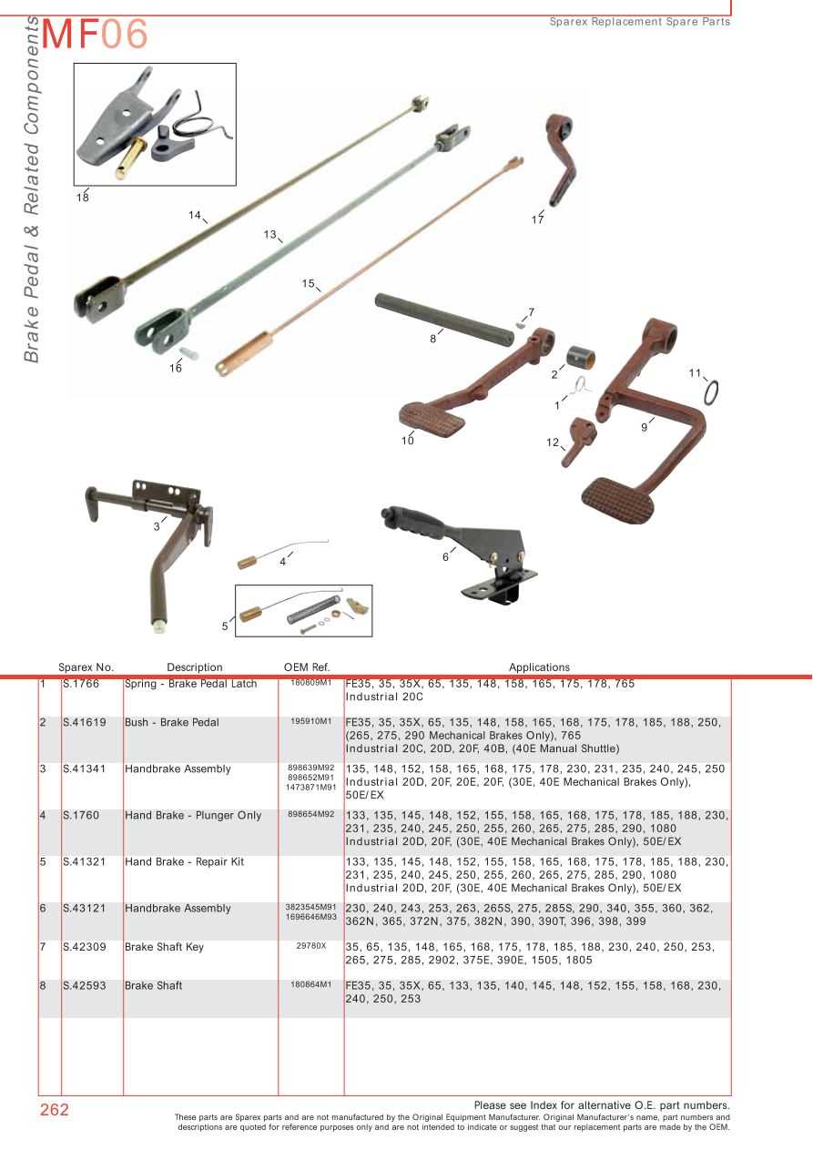
This section provides an overview of the braking mechanism, highlighting its components and their interconnections. Understanding this system is crucial for ensuring safe and efficient operation, as it plays a vital role in controlling speed and stopping power. Detailed insights into each part will aid in troubleshooting and maintenance, allowing operators to keep the machinery in optimal working condition. Key Components of the Braking Mechanism
The braking system consists of several essential elements that work together to provide reliable stopping power. The main components include the brake pedal, master cylinder, brake lines, and wheel cylinders. Each part has a specific function that contributes to the overall efficiency of the braking process.
Maintenance Tips
Regular maintenance of the braking system is essential for safety and performance. Check the hydraulic fluid levels frequently, inspect for leaks in the lines, and ensure the brake pads are in good condition. Proper upkeep will enhance the longevity and effectiveness of the braking components. Fuel System Parts Mapping
The fuel system is essential for the efficient operation of any agricultural machine. Understanding the various components involved in this system is crucial for maintenance and troubleshooting. Each element plays a specific role in ensuring that fuel is delivered properly to the engine, contributing to optimal performance. This section outlines the key components of the fuel system, detailing their functions and interconnections. Familiarity with these elements aids in recognizing potential issues and implementing effective solutions.
Cabin Interior and Controls Layout
The interior of the operator’s compartment is designed to provide a comfortable and efficient working environment. The arrangement of controls and instruments is crucial for enhancing productivity and ensuring ease of operation. A well-organized layout allows the operator to access essential functions quickly while maintaining focus on the task at hand. Control Arrangement
Controls are strategically placed to minimize movement and maximize usability. Key elements include:
Instrument Panel FeaturesThe instrument panel is equipped with various gauges and indicators, providing the operator with real-time information about the machine’s status. This includes:
Cooling System Components and Arrangement
The cooling system of an agricultural vehicle is vital for maintaining optimal engine temperature and preventing overheating. This arrangement comprises various components that work in harmony to dissipate heat generated during operation. Understanding the layout and functionality of these elements is essential for effective maintenance and troubleshooting. Key Components of the Cooling System
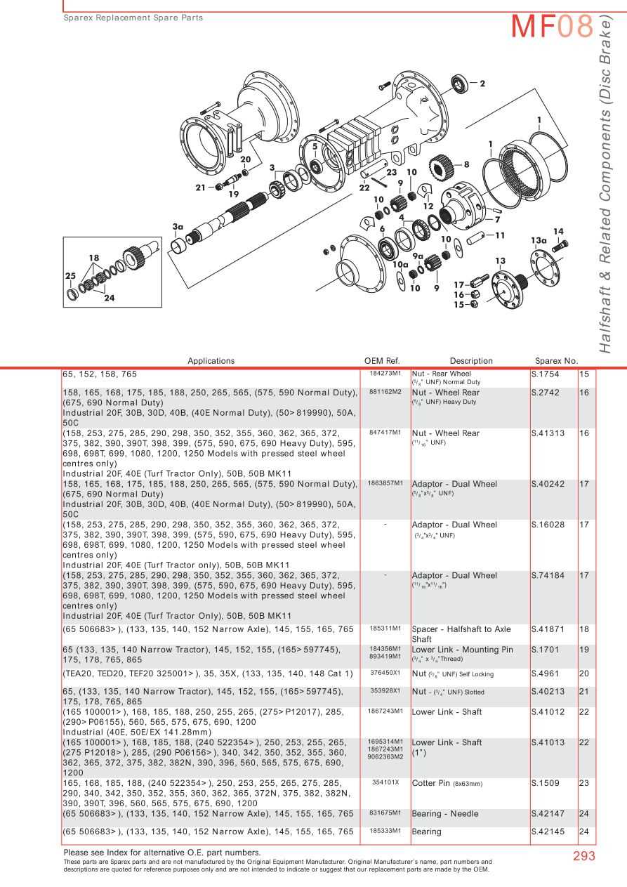
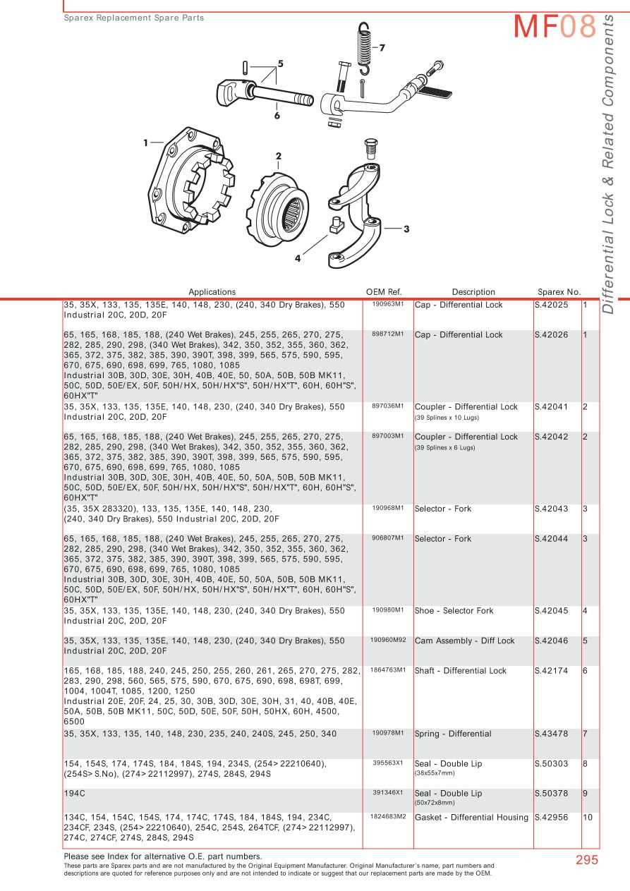
At the heart of the cooling assembly lies the radiator, which plays a crucial role in heat exchange. It circulates coolant, absorbing heat from the engine and releasing it into the atmosphere. Coupled with the radiator is the water pump, which ensures a consistent flow of coolant throughout the system, facilitating efficient thermal regulation. Additional components include the thermostat, which monitors coolant temperature and regulates its flow, and hoses that connect these critical parts, allowing for seamless coolant circulation. Arrangement and FunctionalityThe strategic arrangement of these components is designed for maximum efficiency. The radiator is positioned at the front of the vehicle, where it can effectively draw in air while the engine is in motion. The water pump is typically located near the engine block, minimizing the distance the coolant must travel. This layout not only enhances cooling efficiency but also simplifies maintenance access, allowing for easier inspections and repairs. Proper alignment and secure connections of hoses and fittings are crucial to prevent leaks and ensure a reliable cooling operation. Rear Axle and Differential AssemblyThe rear axle and differential assembly plays a crucial role in the overall performance of agricultural machinery. This component ensures efficient power transmission from the engine to the wheels, allowing for optimal traction and stability during operation. Understanding the assembly involves recognizing its key functions and parts:
Regular maintenance of the rear axle and differential assembly is essential for preventing wear and ensuring longevity. Proper lubrication and inspection of seals can help mitigate potential issues that may arise over time. Understanding these elements can significantly enhance the performance and reliability of the equipment. |
