Understanding the 6.4 Powerstroke Turbo Parts Diagram for Efficient Repairs

In any high-performance engine, understanding the relationships between its various mechanisms is crucial. One of the key elements involves intricate systems designed to enhance power and efficiency, where airflow dynamics play a major role. Familiarity with how these components are structured and interconnected ensures smoother operation and better maintenance.
Exploring the arrangement of mechanical elements related to air compression and circulation reveals a detailed network that supports overall engine function. Each piece is meticulously crafted and positioned to optimize output and durability, requiring an understanding of both design and application.
Whether you’re maintaining or upgrading an engine, knowledge of this system’s layout is essential. Knowing how each part contributes to enhanced performance allows for
Overview of the 6.4 Powerstroke Turbocharger System
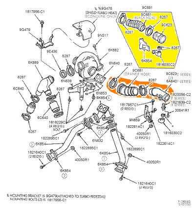
The high-performance engine relies on a carefully designed air compression mechanism to maximize efficiency and power. This system enhances the combustion process by delivering increased oxygen flow to the engine, allowing for greater energy output while maintaining fuel efficiency.
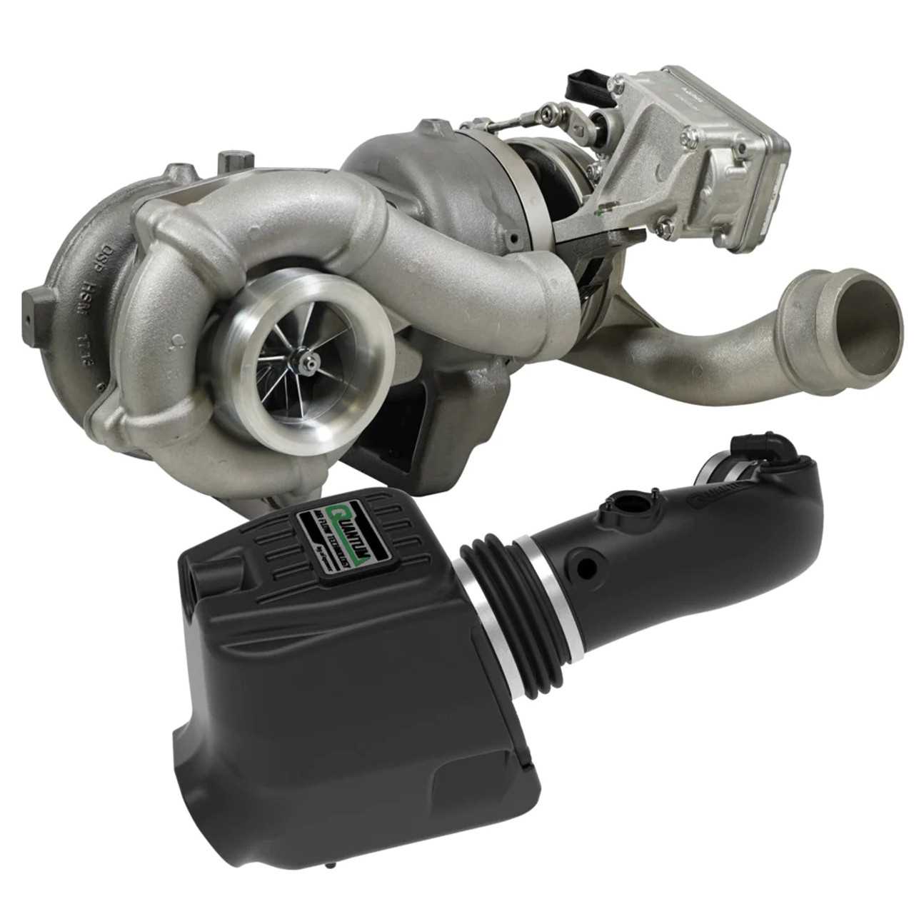
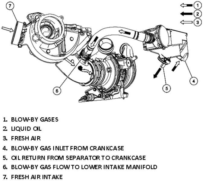
At its core, the system includes two key components that work together to achieve optimal pressure and airflow balance. By combining a small, fast-acting section with a larger, more powerful component, the design effectively reduces lag and increases responsiveness under various driving conditions.
Additional elements such as valves, pipes, and cooling systems ensure proper functionality by regulating air temperature and controlling pressure levels. These interconnected parts ensure smooth operation and help maintain longevity and performance of the entire setup, even under heavy workloads.
Key Components in the Turbo Assembly
The efficient operation of a vehicle’s engine relies on a system of interconnected mechanical elements that work together to enhance performance. This section outlines the critical components involved in this system, ensuring proper airflow management and boosting the overall power of the engine.
| Component | Function | |||||||||||||||||||||||
|---|---|---|---|---|---|---|---|---|---|---|---|---|---|---|---|---|---|---|---|---|---|---|---|---|
| Compressor Wheel | This element is responsible for drawing in air and compressing it before it’s introduced into the engine’s combustion chambers, optimizing fuel efficiency. | |||||||||||||||||||||||
| Turbine Housing |
| Component | Function | Material |
|---|---|---|
| Supply Line | Delivers oil to the component for lubrication | Steel braided hose |
| Return Line | Carries used oil back to the reservoir | Flexible rubber hose |
| Oil Cooler Line | Transfers oil to and from the cooler | Stainless steel tube |
Coolant Flow and Heat Dissipation
The efficient movement of cooling fluid and the effective dissipation of excess heat are crucial for maintaining optimal engine performance. These processes are interlinked, ensuring that temperature levels are controlled to avoid damage to sensitive components. Proper heat management prevents thermal overload and helps maintain the longevity of various engine elements.
In any internal combustion engine, the cooling system is designed to circulate fluid to absorb heat generated by the engine’s operation. This fluid then flows through various channels to release the accumulated heat, ensuring the engine remains within a safe operating temperature range.
- Coolant is drawn from the reservoir and pumped into the engine system, where it circulates through the critical components.
- The fluid absorbs heat as it moves, which is then transferred away from the engine’s core parts.
- Heat exchangers, such as radiators, assist in cooling the fluid before it reenters the system.
- The heat dissipation process helps prevent overheating and maintains component integrity, ensuring smooth operation.
Several factors influence coolant flow and heat dissipation efficiency:
- Coolant Temperature: The ability of the fluid to absorb and carry away heat is directly related to its temperature and chemical composition.
- Flow Rate: An optimal flow rate ensures that the coolant is evenly distributed across all components, enhancing cooling efficiency.
- Heat Transfer Surfaces: The design of the engine and its cooling components, including radiators and heat exchangers, affects how effectively heat is transferred away from the engine.
Regular maintenance of the cooling system, including checking coolant levels and ensuring no blockages or leaks, is essential for the system to function effectively and prevent engine damage from heat buildup.
Wastegate Operation and Importance
The wastegate is a crucial component that helps regulate the performance of a forced induction system by controlling exhaust gas flow. It plays a vital role in ensuring that the engine operates within safe pressure limits, preventing overboosting. By managing the flow of gases, it prevents damage to the engine and enhances efficiency.
When the engine reaches a specific pressure, the wastegate opens, allowing excess gases to bypass the system. This ensures that the pressure inside the engine remains stable, preventing any potential damage from excess boost levels.
- Function: The wastegate regulates exhaust flow to control boost pressure and engine performance.
- Prevention of Overboost: It opens when the set pressure is exceeded, preventing the engine from receiving too much boost.
- Performance Impact: A well-functioning wastegate ensures optimal power output and engine safety.
- Efficiency: By controlling the flow of exhaust gases, the wastegate helps maintain consistent power delivery.
The operation of the wastegate is essential to the overall longevity and reliability of the engine. Without proper wastegate functionality, the risk of mechanical failure and poor performance increases significantly.
Intercooler Connections and Efficiency
Effective management of air temperature plays a crucial role in the performance of an engine system. The components responsible for cooling the intake air are designed to ensure that the engine operates at optimal efficiency. Proper connections within this system are key to achieving the desired results, as they maintain the flow and temperature control necessary for peak engine performance.
The efficiency of the cooling system depends largely on the design of the pathways through which air flows. These pathways must minimize heat retention and reduce the overall load on the engine. If the connections between various components are not properly sealed or aligned, the entire system’s efficiency can be compromised, leading to lower performance and potential engine stress.
| Component | Function | Impact on Efficiency |
|---|---|---|
| Air Channels | Directs cooled air to the intake | Ensures consistent airflow, preventing overheating |
| Seals and Clamps | Prevents air leaks | Maintains pressure and airflow integrity |
| Cooling Units | Cools the intake air before it enters the engine | Directly influences the temperature of incoming air |
Maximizing system efficiency requires ensuring that all components are not only well-connected but also function in harmony. Proper maintenance of these connections helps to prevent potential air leaks, which could lead to a drop in cooling efficiency and overall engine performance.
Manifold Setup for Optimized Turbo Performance
Ensuring the ideal configuration of the intake and exhaust components is crucial for maximizing engine efficiency and overall performance. The arrangement of these elements plays a significant role in improving airflow, reducing restrictions, and enhancing power output. By focusing on the precise placement and integration of these systems, an engine can achieve smoother power delivery and quicker response times.
Proper alignment of the intake and exhaust manifolds is essential for minimizing turbo lag and maximizing airflow dynamics. When the components are strategically arranged, the engine operates more efficiently, leading to enhanced combustion and a smoother driving experience.
Optimal materials also contribute to improved performance. High-quality, heat-resistant materials can prevent excessive thermal losses and maintain system integrity, even under high pressure and temperature conditions. This ensures consistent performance and durability over time.
Common Turbo Wear Points and Maintenance
Regular upkeep and awareness of key components in forced induction systems are crucial for maintaining optimal performance. Certain areas of these systems are more prone to wear and damage due to high heat, pressure, and friction. Recognizing these vulnerable spots and taking proactive measures can prevent costly repairs and downtime.
One of the primary wear points involves the bearings and shafts that allow rotation at high speeds. Over time, heat and stress can cause these parts to degrade, leading to a reduction in efficiency or even failure. Routine inspection of lubrication and oil lines helps ensure these components remain properly maintained.
Another critical area is the seals, which can wear down due to the pressure exerted during operation. This can lead to leaks, compromising the system’s effectiveness. Monitoring the condition of these seals and replacing them at the first sign of wear is essential for continued reliability.
Lastly, the fins or blades responsible for airflow can suffer from damage caused by debris or over-speeding. Regular cleaning and careful handling are essential to maintain their integrity, ensuring that they can function efficiently for longer periods.

