Understanding the Stenner Pump Parts Diagram for Efficient Maintenance
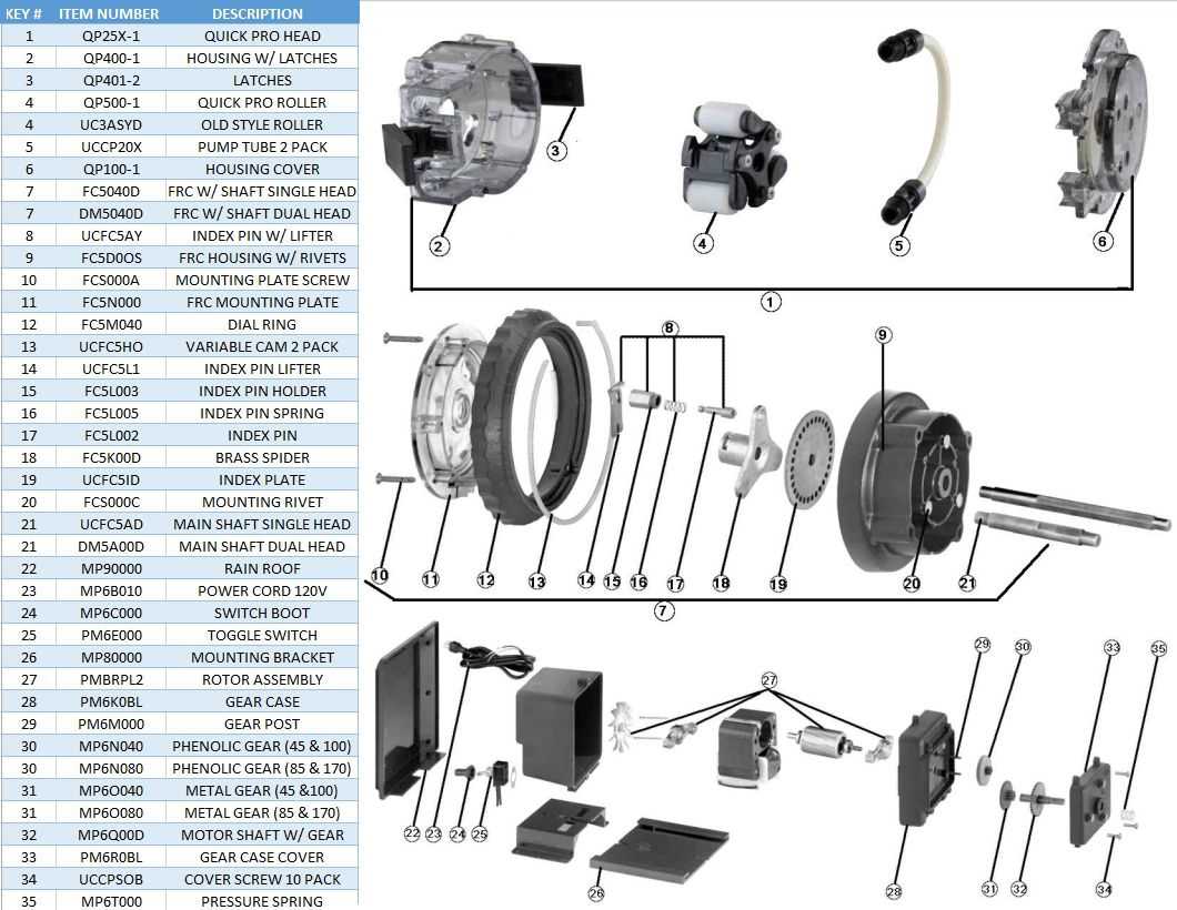
In the realm of fluid delivery systems, grasping the intricacies of individual components is essential for effective operation and maintenance. A comprehensive overview of how these elements interact can greatly enhance the user’s experience and ensure optimal functionality. Each section of the assembly plays a vital role in the overall performance, making familiarity with their arrangement crucial for both troubleshooting and upgrades.
Visual representations of these assemblies provide invaluable insights, allowing users to identify each segment’s purpose and relationship with others. This kind of schematic not only simplifies the learning process but also serves as a handy reference during repairs or modifications. By examining these layouts, one can better appreciate the precision engineering that goes into creating efficient systems.
Moreover, understanding the configuration of each unit empowers operators to make informed decisions regarding replacements or enhancements. Whether one is a seasoned technician or a novice, having access to a clear illustration fosters confidence and competence in handling these complex mechanisms. Ultimately, a solid grasp of the configuration is fundamental for anyone looking to master the art of fluid management.
Understanding Stenner Pumps
This section delves into the mechanics and components of a specific type of dosing equipment used in various applications. These devices are essential for precise fluid delivery, ensuring accuracy in chemical injection for tasks such as water treatment and agricultural processes. By exploring the underlying principles and elements, one can gain a clearer understanding of their functionality and importance in maintaining system efficiency.
The construction of these devices typically involves several key components, each serving a unique purpose in the overall operation. A basic overview of these elements can help users troubleshoot and optimize their systems effectively. Below is a simplified representation of the major components and their functions:
| Component | Description |
|---|---|
| Motor | Drives the mechanism, converting electrical energy into mechanical motion. |
| Head Assembly | Houses the dispensing mechanism, regulating fluid flow and pressure. |
| Tubing | Transports the liquid from the source to the application point. |
| Control System | Manages the operational settings, allowing for adjustments in delivery rates. |
| Calibration Mechanism | Ensures accuracy in fluid delivery by allowing for precise adjustments. |
Understanding these components not only aids in effective usage but also empowers users to perform maintenance and repairs, enhancing longevity and reliability in diverse operational environments.
Key Components of Stenner Pumps
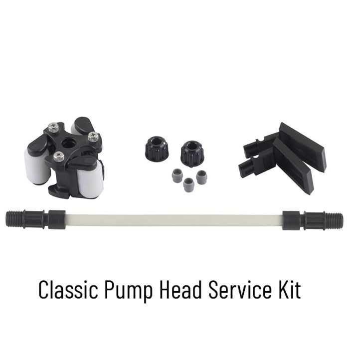
Understanding the fundamental elements of a fluid delivery system is essential for effective operation and maintenance. Each component plays a crucial role in ensuring reliability, accuracy, and efficiency in the overall process.
- Drive Mechanism: This is the heart of the system, responsible for converting electrical energy into mechanical motion. It ensures consistent flow rates and precise dosing.
- Injection Valve: This component controls the entry of fluid into the system. It is vital for maintaining the correct pressure and flow, thereby optimizing performance.
- Check Valve: A critical safety feature, it prevents backflow, ensuring that the liquid only moves in one direction and maintaining system integrity.
- Metering Tube: The section where the fluid is conveyed. Its design influences the system’s overall efficiency and accuracy in dispensing the desired volume.
- Foot Valve: Located at the inlet, this part prevents siphoning and allows for proper priming of the fluid pathway.
- Housing: The outer shell that protects internal components and maintains structural integrity under various operational conditions.
Each of these elements contributes to the overall functionality, ensuring optimal operation and longevity of the system.
Importance of Pump Maintenance
Regular upkeep of fluid delivery systems is essential for ensuring their longevity and optimal performance. Neglecting maintenance can lead to inefficiencies, increased energy consumption, and unexpected breakdowns, which ultimately affect productivity and operational costs.
Enhanced Reliability
Consistent care minimizes the risk of failures, thereby enhancing the reliability of the equipment. Scheduled inspections allow for the identification of wear and tear before they escalate into significant issues. By addressing minor concerns promptly, one can avoid costly repairs and downtime.
Cost Efficiency
Investing time and resources into routine maintenance can lead to substantial cost savings in the long run. Preventive measures often prove to be less expensive than reactive repairs. Moreover, well-maintained systems typically operate more efficiently, translating to lower energy expenses and improved overall performance.
Common Issues with Stenner Parts
Understanding the typical challenges that can arise with these devices is essential for effective maintenance and troubleshooting. Various components can experience wear and tear or malfunction, leading to reduced efficiency or complete failure. Identifying and addressing these common problems can help ensure optimal performance and longevity.
One frequent concern involves leaks, which can occur at seals or connections. Such leaks not only compromise the system’s effectiveness but can also create hazardous conditions if not promptly addressed. Regular inspection of seals and tightening of fittings can mitigate this issue.
Another prevalent issue is the wear of the mechanical elements, which can lead to inconsistent operation. This may manifest as irregular flow rates or noise during operation. Periodic checks and timely replacement of worn-out components can help maintain smooth functionality.
Electrical faults are also common, often stemming from wiring issues or malfunctioning control units. Ensuring that all electrical connections are secure and that components are free from corrosion can prevent these complications.
Lastly, buildup of residue can impede performance, leading to clogs or reduced efficiency. Implementing a regular cleaning schedule can help keep the system functioning optimally and prevent unnecessary repairs.
Diagram Analysis of Stenner Pumps
This section delves into the visual representation of a specific type of fluid delivery device. By examining its components and their interrelations, we can gain insights into the functionality and efficiency of the system. Understanding the layout and design is crucial for both troubleshooting and optimizing performance.
The following table outlines the key elements and their respective functions within the assembly:
| Component | Description |
|---|---|
| Drive Mechanism | Responsible for initiating movement and controlling flow rate. |
| Check Valve | Prevents backflow, ensuring fluid only moves in one direction. |
| Dispensing Head | Where the fluid is released, designed for precision delivery. |
| Tube Assembly | Conduits for transporting fluid from the source to the destination. |
| Mounting Bracket | Secures the device in place, providing stability during operation. |
Analyzing the structure not only aids in better understanding but also highlights potential areas for improvement. By breaking down each element, operators can enhance efficiency and address any operational challenges that may arise.
How to Read Pump Diagrams
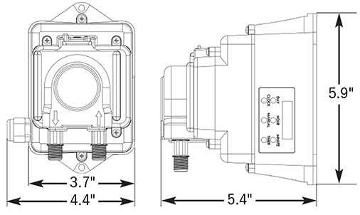
Understanding technical illustrations is crucial for effective maintenance and troubleshooting. These visual representations provide essential information about the components and their interconnections. Familiarity with the symbols and layout can greatly enhance comprehension and facilitate efficient operation.
Key Components and Symbols
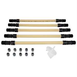
Most visual aids feature standardized symbols that represent various elements. Familiarizing yourself with these symbols is the first step to deciphering the illustration. Each component, such as valves and connectors, typically has a unique icon. Pay attention to the accompanying legends or keys, which explain the meaning of each symbol.
Reading the Layout
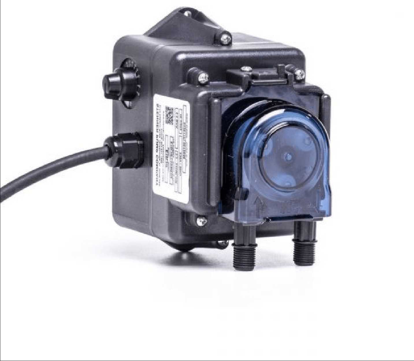
The arrangement of components in the illustration is equally important. Often, the flow of liquid or air is indicated by arrows, guiding you through the system’s functionality. Observe how elements are interconnected and take note of any specific sequences or arrangements that could affect performance. This will help you visualize the system’s operation in a real-world context.
Replacing Stenner Pump Components
Maintaining the functionality of your dispensing device is essential for optimal performance. Over time, certain elements may wear out or become less efficient, necessitating their replacement. Understanding the process of exchanging these components can help ensure that your system operates smoothly and effectively.
Identifying the Components
Begin by familiarizing yourself with the various elements that make up your system. Common components include the motor, tubing, and check valves. Each part plays a crucial role in the overall operation, and recognizing which ones require attention is key to a successful maintenance routine.
Gathering Necessary Tools
Before starting the replacement process, ensure you have the appropriate tools at hand. Basic tools like screwdrivers, wrenches, and pliers will likely be required. Having these ready will streamline the replacement procedure and minimize downtime.
Step-by-Step Replacement
Once you have identified the worn components and gathered your tools, you can proceed with the replacement. Carefully disconnect the device from its power source. Follow the manufacturer’s guidelines for removing the faulty parts, and ensure that all connections are secure when installing new components. Take care to align everything properly to avoid future issues.
Testing and Calibration
After replacing the components, it is vital to test the device to ensure everything is functioning as intended. Monitor the system closely during initial operation and make any necessary adjustments. Proper calibration can enhance performance and prolong the lifespan of your equipment.
Regular maintenance and timely replacements will not only enhance efficiency but also help prevent unexpected breakdowns in the future. By staying proactive, you can ensure that your dispensing system remains reliable and effective.
Benefits of Genuine Parts
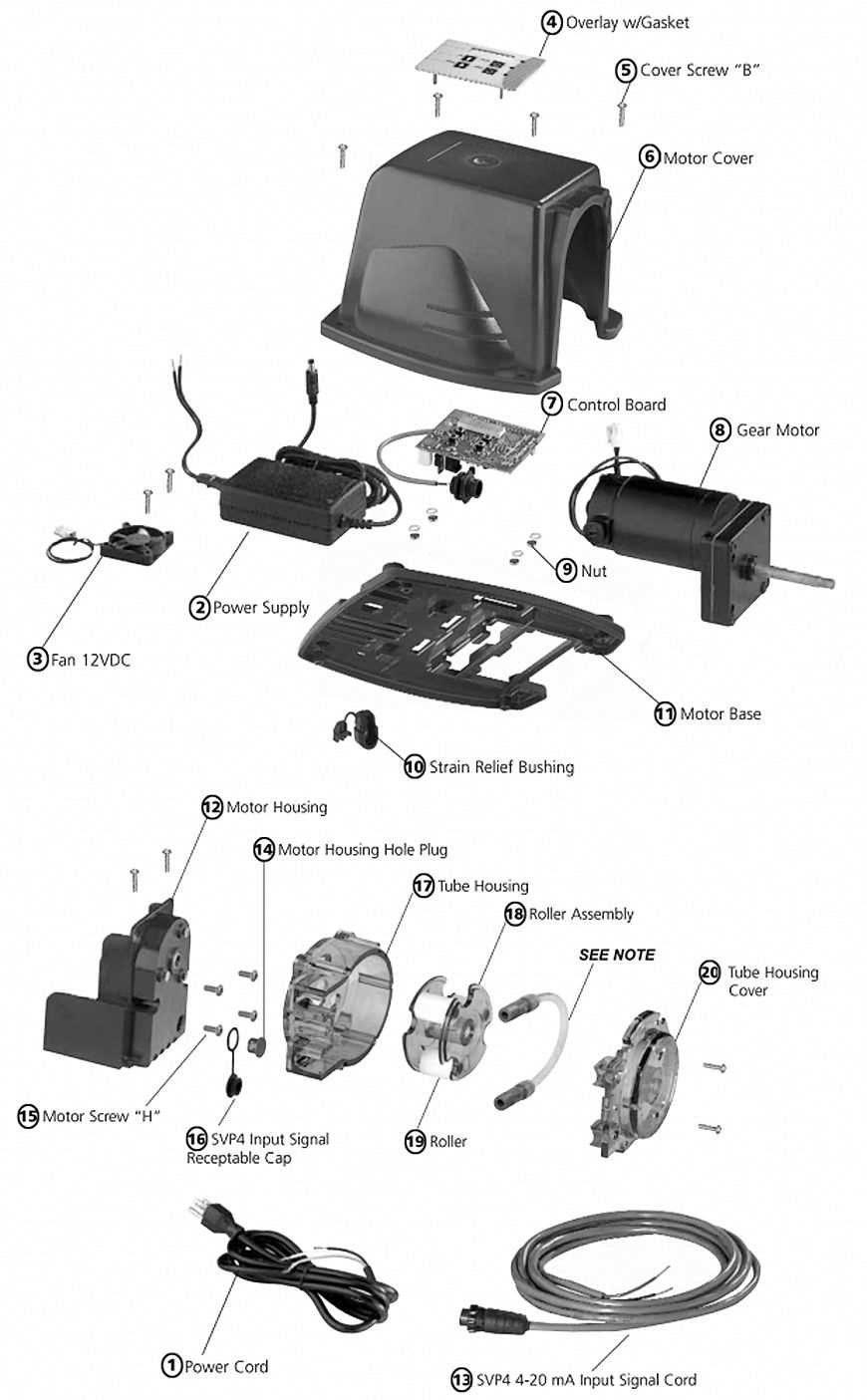
Using authentic components in any mechanical system ensures optimal performance and longevity. These original items are designed to meet strict specifications, providing reliability and efficiency that replicas often fail to deliver.
Quality Assurance
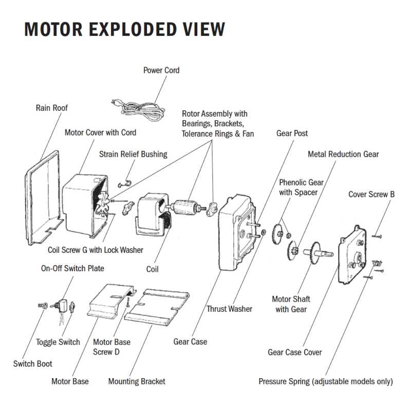
One of the primary advantages of selecting genuine items is the assurance of quality. Authentic components are manufactured under rigorous standards, which translates to:
- Enhanced durability
- Consistent performance
- Compatibility with existing systems
Cost-Effectiveness
While the initial investment for original components may be higher, they often lead to long-term savings. Consider the following:
- Reduced maintenance costs due to fewer breakdowns
- Extended lifespan, resulting in less frequent replacements
- Better resale value for systems equipped with genuine components
Safety Tips for Pump Operation
Ensuring safe and efficient functioning of fluid transfer systems requires adherence to essential guidelines. Proper precautions not only protect operators but also enhance the longevity and reliability of the equipment.
- Always read the manufacturer’s manual before use to understand specific requirements and safety protocols.
- Inspect the equipment regularly for any signs of wear, damage, or leaks to prevent accidents.
- Ensure all connections are secure to avoid spills or unexpected discharges.
- Use personal protective equipment (PPE) such as gloves, goggles, and masks to safeguard against harmful substances.
- Maintain a clean and organized work area to minimize hazards and improve operational efficiency.
In addition to these precautions, consider the following practices:
- Train all personnel on proper operation techniques and emergency procedures.
- Establish a routine maintenance schedule to keep the system in optimal condition.
- Be aware of the environmental conditions and potential impacts on the equipment’s performance.
- Keep emergency contact information readily available in case of incidents.
By following these safety tips, operators can ensure a smooth and secure experience while managing fluid transfer tasks.
Resources for Pump Repair Information
Accessing reliable resources is crucial for effective maintenance and troubleshooting of fluid transfer devices. These resources can help technicians understand components, find solutions to common issues, and acquire necessary skills for repairs. With the right information, users can ensure optimal performance and longevity of their equipment.
Online Forums and Communities
Engaging with online platforms allows users to connect with fellow enthusiasts and experts. These communities provide a space to share experiences, ask questions, and seek advice on various repair challenges.
Manufacturer Manuals and Guides
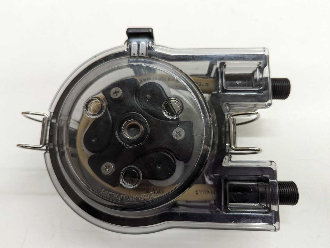
Official documentation from manufacturers is invaluable. Manuals typically contain detailed instructions, diagrams, and specifications that assist in both troubleshooting and repair tasks.
| Resource Type | Description | Link/Contact |
|---|---|---|
| Online Forums | Community-driven discussions on repair techniques and tips. | www.exampleforum.com |
| Technical Manuals | Official guides with detailed procedures and part specifications. | www.examplemanuals.com |
| Video Tutorials | Step-by-step visual instructions for common repair tasks. | www.examplevideos.com |