Comprehensive Guide to Thor Range Parts Diagram
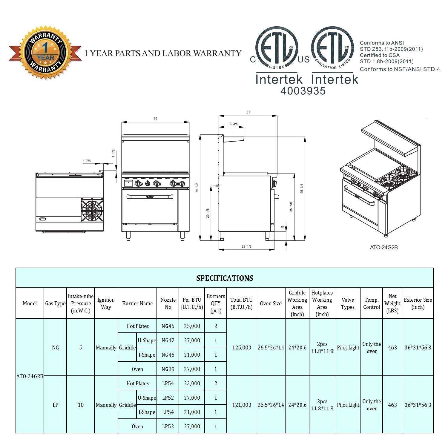
Understanding the intricate assembly of equipment is essential for optimal performance and maintenance. A well-structured overview of individual elements can significantly enhance both functionality and efficiency. By examining the relationships between various segments, users can grasp how to troubleshoot issues effectively.
In this exploration, we will uncover the arrangement of crucial units, shedding light on their roles and interconnections. This knowledge serves as a foundation for anyone looking to improve their hands-on skills or simply gain a deeper appreciation for engineering design.
By delving into the specifics of these configurations, readers will ultimately be equipped with the insights needed to tackle challenges and enhance their overall expertise. The following sections will provide a comprehensive look at the components and their assembly, facilitating a clearer understanding of how they work together harmoniously.
Understanding the Thor Range Parts Diagram
The layout of components in a system is crucial for effective operation and maintenance. Grasping the arrangement and function of each element can significantly enhance both performance and troubleshooting processes. This section delves into the intricacies of such layouts, providing insights into their design and utility.
Key Components and Their Functions
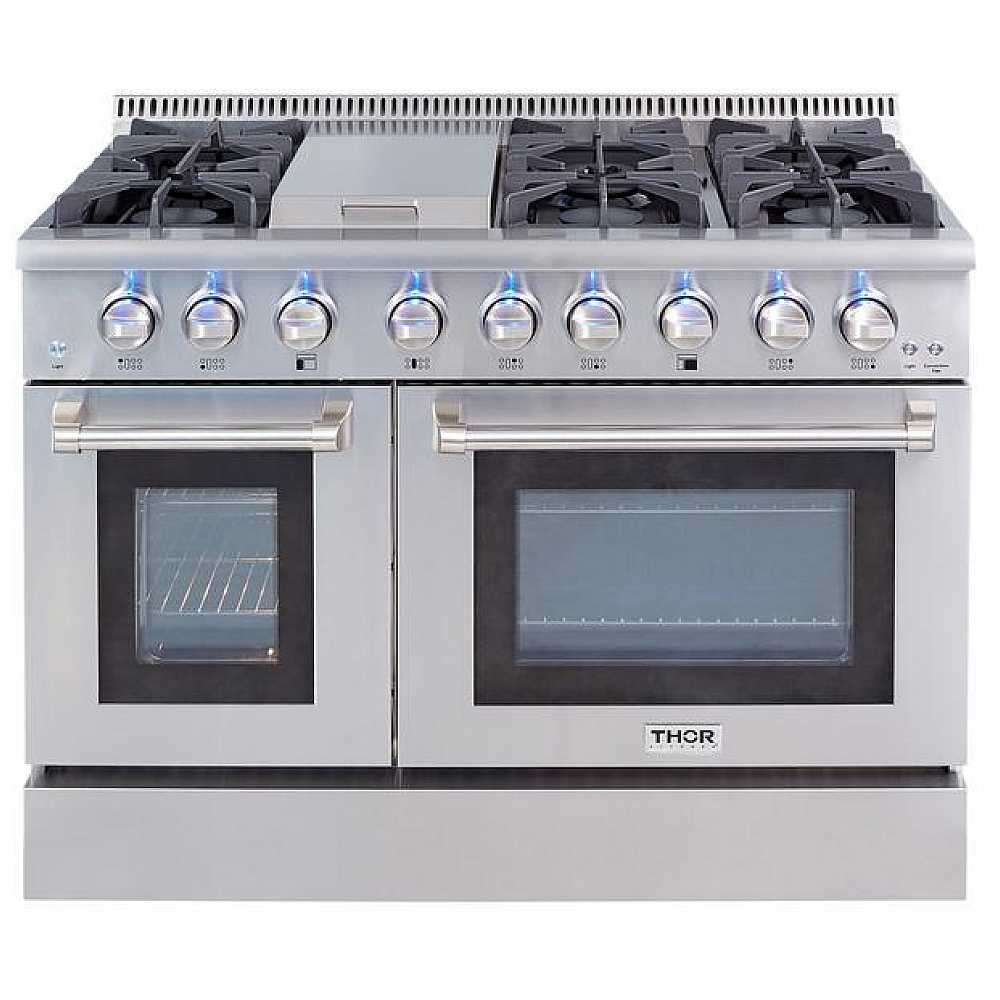
Every system consists of various elements that work in unison. Understanding the role of each part allows for better manipulation and control over the entire mechanism. Below is a brief overview of some essential components:
| Component | Function |
|---|---|
| Element A | Responsible for initiating the operation. |
| Element B | Facilitates energy transfer throughout the system. |
| Element C | Ensures stability and support during operation. |
| Element D | Acts as a control mechanism to adjust performance. |
Interconnection of Components
The interaction among various parts is vital for seamless functionality. Each element influences the others, forming a network that dictates overall efficiency. Recognizing these connections is essential for optimizing performance and conducting effective repairs.
Key Components of the Thor Range
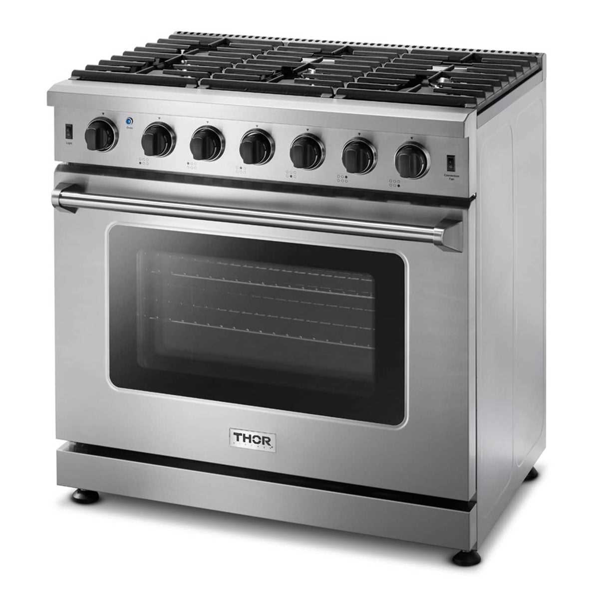
This section explores the essential elements that contribute to the functionality and performance of the system. Understanding these components is crucial for anyone looking to enhance their knowledge and experience with the equipment.
Main Elements
- Power Source: The core of the equipment, providing the necessary energy for operation.
- Control Unit: The interface that allows users to manage and adjust settings effectively.
- Heating Mechanism: Responsible for generating and maintaining desired temperatures.
- Safety Features: Include mechanisms designed to protect both the equipment and users during operation.
- Structural Frame: The backbone that supports all other components and ensures durability.
Supporting Accessories
- Connectors: Facilitate the integration of various components for seamless operation.
- Insulation: Enhances energy efficiency by minimizing heat loss.
- Maintenance Tools: Essential for ensuring longevity and optimal performance of the system.
- Calibration Instruments: Allow for precise adjustments and monitoring of performance metrics.
Benefits of Using a Parts Diagram
Utilizing a visual representation of components offers numerous advantages for both novices and experts. It simplifies the process of understanding complex systems, ensuring that users can identify and locate individual elements quickly and efficiently.
Enhanced Clarity
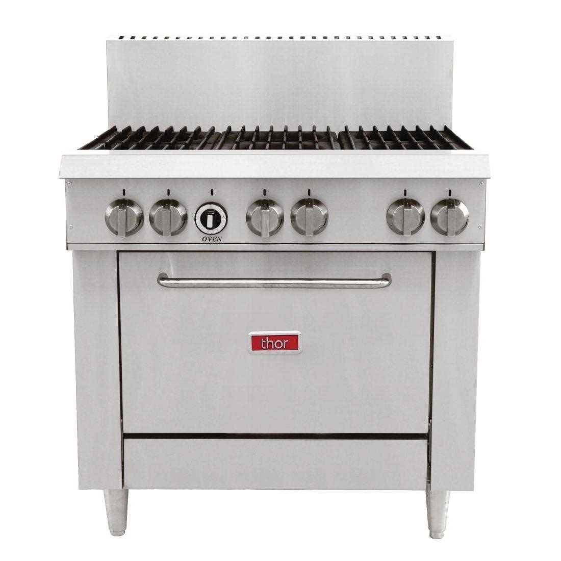
Having a graphical layout provides clear insights into how different elements interact. This clarity can reduce confusion, making it easier to troubleshoot issues or plan maintenance.
Streamlined Repairs
When it comes to fixing or replacing elements, a visual guide can significantly speed up the process. Users can quickly refer to the illustration to find the specific components needed, minimizing downtime and enhancing overall productivity.
How to Read the Diagram Effectively
Understanding a visual representation of components can enhance your ability to assemble or troubleshoot a device. This section will guide you through the essential steps to interpret such illustrations successfully.
To begin, familiarize yourself with the overall layout:
- Identify the main sections and how they relate to each other.
- Look for a legend or key that explains symbols and notations.
- Take note of the scale, as it helps in visualizing dimensions accurately.
Next, focus on specific elements:
- Trace the connections between different components.
- Pay attention to any directional arrows that indicate movement or flow.
- Note any annotations that provide additional information or specifications.
Finally, practice interpreting these visuals by working on small projects or exercises. This hands-on approach will reinforce your understanding and improve your skills in reading complex illustrations.
Common Issues Identified in Diagrams
Understanding the visual representations of components is crucial for effective troubleshooting and maintenance. However, several recurring challenges can complicate this process, leading to confusion and potential errors.
| Issue | Description |
|---|---|
| Ambiguous Labels | Vague or unclear terms can lead to misinterpretation of the components. |
| Inconsistent Symbols | Variation in symbol usage may confuse users familiar with different standards. |
| Lack of Detail | Insufficient information on specific parts can hinder proper identification and assessment. |
| Overly Complex Layouts | Intricate designs can overwhelm users, making it difficult to focus on essential elements. |
Maintenance Tips for Thor Range Parts
Ensuring the longevity and optimal performance of your kitchen appliance requires regular upkeep. By following a few simple strategies, you can enhance efficiency and prevent costly repairs. Proper care not only extends the life of your equipment but also ensures safety during use.
Regular Cleaning
Keep surfaces and components clean to avoid buildup that can hinder functionality. Use mild detergents and soft cloths to wipe down areas. For stubborn stains, a gentle scrub with baking soda can work wonders. Regular maintenance creates a hygienic environment for cooking.
Periodic Inspections
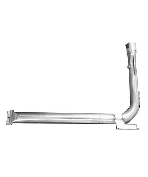
Routine checks are essential for identifying wear and tear. Look for loose connections, frayed wires, or signs of corrosion. Timely detection of these issues can prevent major breakdowns and ensure your equipment operates smoothly. Always consult the user manual for specific guidelines.
Identifying Replacement Parts Easily
Finding the right components for your equipment can be a daunting task. Understanding how to navigate various resources and tools can significantly simplify the process. With a bit of knowledge and the right approach, you can efficiently pinpoint the exact items you need for a successful repair or upgrade.
Visual Guides play a crucial role in this endeavor. Utilizing comprehensive charts or illustrations can provide clarity, allowing you to match the required pieces with ease. Make sure to refer to high-quality images that clearly depict each element, making identification straightforward.
Cross-referencing is another effective strategy. By comparing product numbers or specifications across different sources, you can ensure compatibility. Many manufacturers offer online databases where you can input your model details, streamlining the search process.
Additionally, consider engaging with online communities or forums dedicated to your equipment. Enthusiasts and professionals often share valuable insights and experiences that can guide you toward the right selections. Their firsthand knowledge can save you time and effort while providing recommendations based on practical experience.
Comparison with Other Range Models
This section explores the distinctions and similarities among various models within the same category. Understanding these differences can help users make informed choices based on their specific needs and preferences.
Key Differences
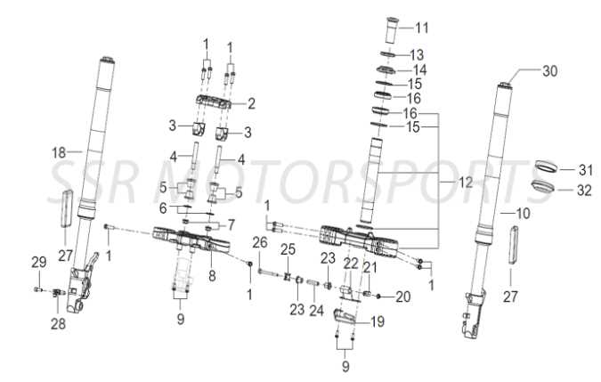
- Design and Build Quality
- Performance Metrics
- User Interface and Control Features
Similarities
- Basic Functionality
- Target Audience
- Market Positioning
When evaluating options, it’s essential to consider how these models stack up against one another in terms of reliability and usability.
Importance of Accurate Diagrams
Precise visual representations play a crucial role in understanding complex systems. They serve as essential tools for effective communication, enabling individuals to interpret intricate details with clarity. By providing a clear overview, these illustrations facilitate easier identification of components and their relationships.
| Benefits | Description |
|---|---|
| Enhanced Clarity | Accurate visuals simplify complex information, making it easier to grasp. |
| Improved Communication | Clear representations foster better understanding among team members. |
| Efficient Troubleshooting | Visual aids help quickly pinpoint issues within a system. |
| Standardization | Consistent imagery ensures everyone is on the same page regarding components. |
Ultimately, the effectiveness of any technical endeavor is significantly influenced by the accuracy of its visual representations. Investing time in creating detailed and precise illustrations can lead to better outcomes in various projects.
Where to Find Official Diagrams
Accessing accurate schematics is crucial for anyone looking to maintain or repair specific equipment. These visual guides provide essential insights into component layout and functionality, ensuring that users can make informed decisions during their projects.
Manufacturer Websites: The most reliable source for authentic illustrations is often the official websites of the manufacturers. Here, you can find a dedicated section for resources that includes downloadable files.
User Manuals: Often overlooked, user manuals typically contain detailed visual representations of the equipment. These documents can be invaluable for understanding assembly and maintenance processes.
Authorized Dealers: Connecting with certified dealers or service centers can lead to obtaining specialized guides that are not readily available online. They often have access to proprietary resources that enhance your understanding.
Online Forums: Communities dedicated to enthusiasts or professionals often share valuable insights and resources. Participating in these forums can lead to discovering hidden gems, including shared diagrams and tips from experienced users.
Service Documentation: Comprehensive service documents may be available through subscription services or technical libraries. These resources often provide in-depth analysis and technical drawings that can aid in troubleshooting.
Real User Experiences with Thor Parts
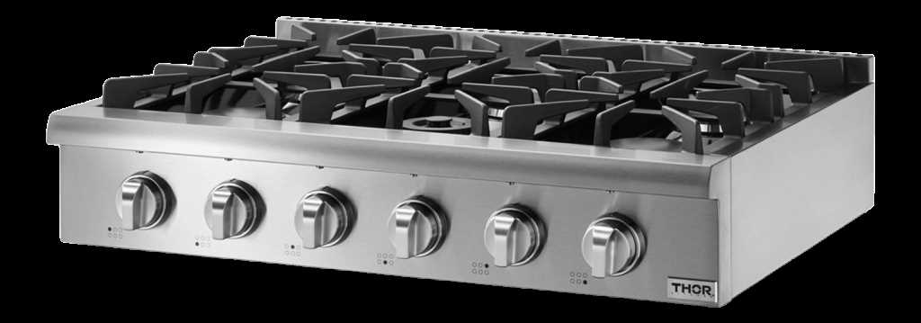
This section delves into the genuine feedback and insights from users who have interacted with various components associated with a specific brand. Their stories highlight the effectiveness, durability, and overall satisfaction that come from using these elements in their projects or daily tasks.
Performance Insights
Many users have reported remarkable performance improvements after integrating these components into their setups. The precision engineering behind each piece often leads to enhanced functionality, resulting in smoother operations. A frequent sentiment among users is the appreciation for the reliability that these components bring to their workflows.
Challenges Faced
While the overall feedback is positive, some individuals have encountered challenges. Issues such as compatibility with existing equipment or the need for specific tools during installation are noted. However, users emphasize that these challenges are typically outweighed by the benefits and that the support community is robust, providing guidance and solutions.
In conclusion, the experiences shared by users paint a comprehensive picture of how these components perform in real-world applications. Their insights are invaluable for potential buyers, offering a clearer understanding of what to expect when choosing these items.
Future Innovations in Range Diagrams
The landscape of schematic representation is evolving rapidly, driven by advancements in technology and a growing emphasis on clarity and usability. As industries increasingly rely on visual tools to communicate complex systems, the need for more intuitive and interactive formats is becoming paramount. Future innovations aim to enhance user experience by integrating real-time data, improved interactivity, and enhanced visualization techniques.
Integration of Augmented Reality
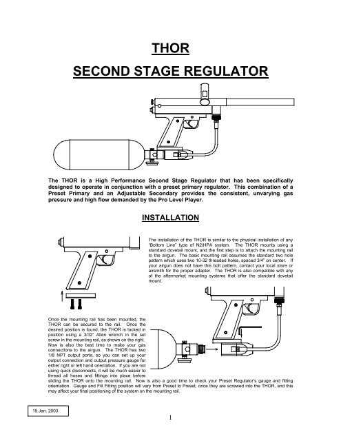
One of the most promising trends is the incorporation of augmented reality (AR) into visual schematics. This technology allows users to engage with three-dimensional models superimposed on their physical environment, facilitating a deeper understanding of the relationships and functions within a system. By enabling dynamic exploration and manipulation, AR can transform traditional representation methods into immersive experiences.
Data-Driven Visualization
Another significant advancement is the shift towards data-driven representations. By harnessing big data and analytics, future visual tools will not only illustrate static relationships but also adapt in real-time based on current metrics and performance indicators. This capability will provide users with a more comprehensive view, allowing for proactive decision-making and enhanced operational efficiency.