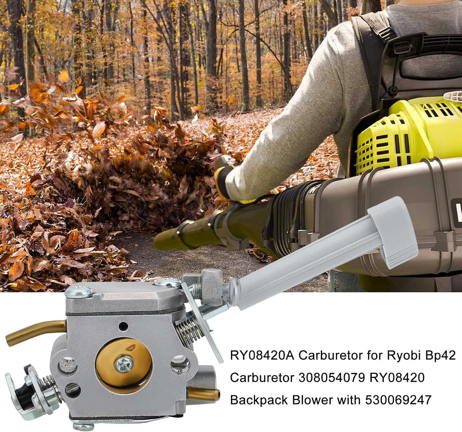
Ryobi bp42 Parts Diagram
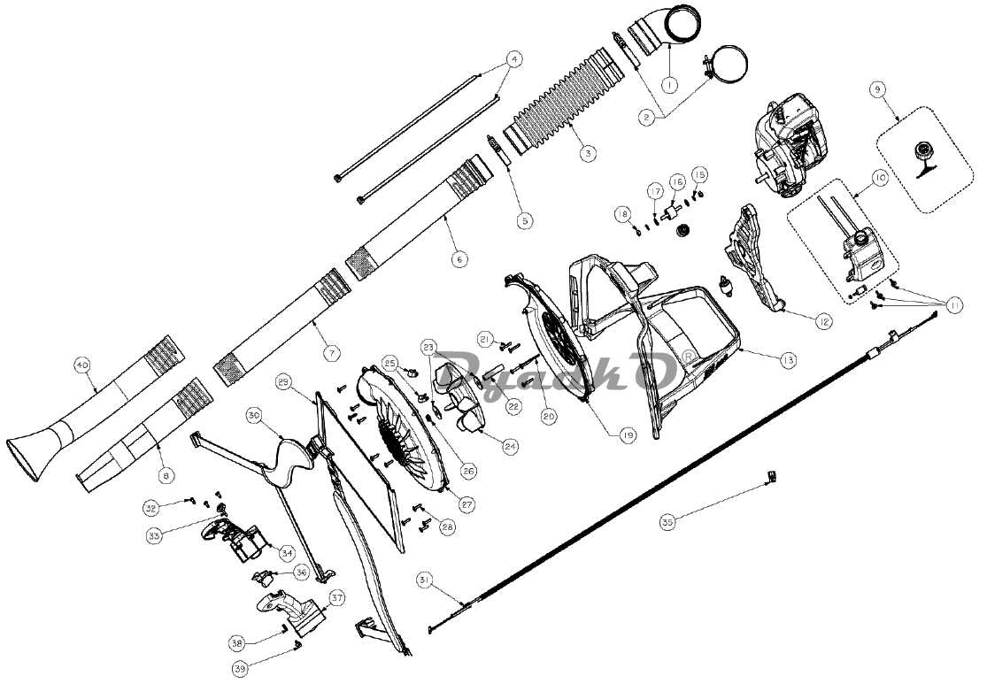
The section focuses on the detailed breakdown of key mechanical elements within an air-moving device. It presents a comprehensive view of the internal structure, highlighting essential components that facilitate optimal performance.
Readers will gain insight into the inner workings of a device designed to generate airflow, revealing the intricate connections between each functional part. This informative segment provides a visual guide through the assembly’s composition, offering clarity on how elements collaborate to achieve operational efficiency.
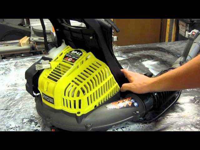
Overview of Components in the BP42 Model
In this section, we will explore the various elements that comprise the BP42 model, providing a detailed look at its internal structure and key parts. Understanding these components is crucial for both maintenance and troubleshooting purposes.
Main Engine Assembly
The core of the BP42 unit includes the primary engine assembly, which powers the entire system. This component integrates several mechanisms that facilitate the efficient operation of the device.
Air Flow System
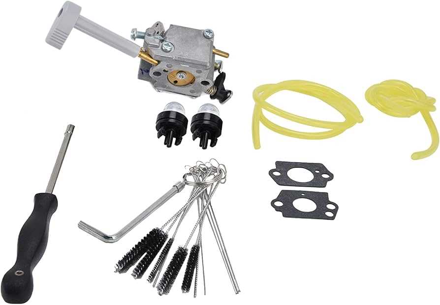
An essential feature of the BP42 is its intricate air flow system, responsible for managing the intake and outflow of air. This system ensures optimal performance during operation, enhancing overall functionality.
Throughout this overview, we will delve into each component’s function and interaction within the BP42, offering insights into its robust design and functionality.
Main Engine Parts of Ryobi BP42
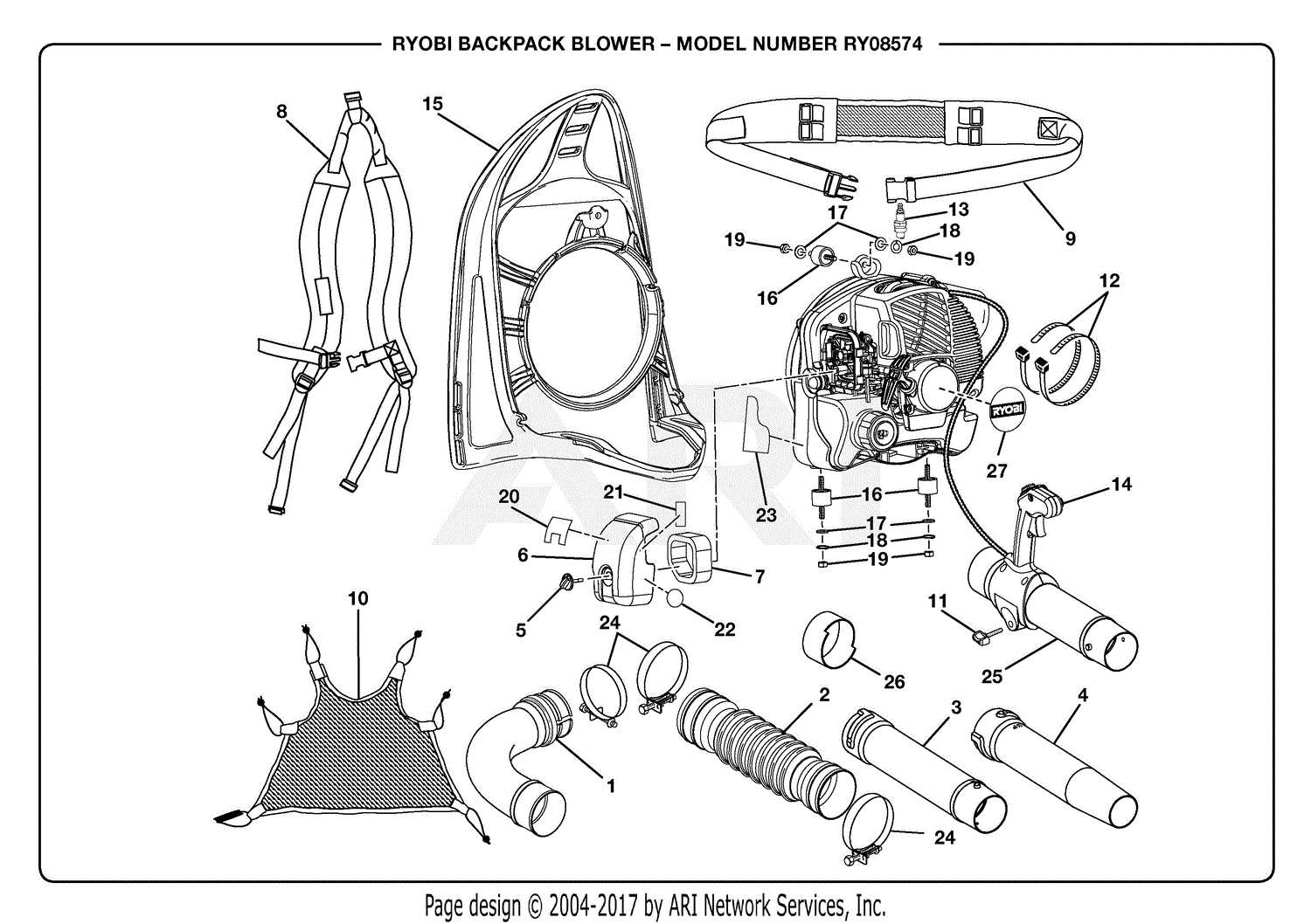
In this section, we explore the key components that make up the core of the Ryobi BP42 engine. We’ll delve into the essential elements responsible for its operation and performance.
- The primary assembly that drives the mechanical functions of the machine.
- A crucial component designed to manage the energy output efficiently.
- An integral part responsible for the combustion process within the engine.
- A component that regulates the intake and exhaust of gases for optimal performance.
- A vital mechanism that ensures the synchronization of various engine functions.
Understanding these core parts provides insight into how the Ryobi BP42 engine operates effectively in different conditions.
Fuel System Breakdown and Diagram
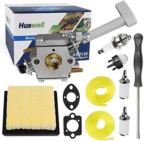
The fuel system is an essential component for ensuring smooth operation, providing the necessary energy to power the engine. This section explores the structure and key elements involved in the fuel delivery process, presenting a clear overview without diving into specific technical terms. The goal is to outline how the fuel flows from the tank to the combustion chamber, highlighting the steps involved in this crucial function.
Main Components Overview
The system comprises several interconnected parts that work together to ensure the proper flow of fuel. These components ensure fuel filtration, regulation, and atomization, making the engine run efficiently. Below is a table summarizing the key elements in the system.
| Component | Function | ||||||||||
|---|---|---|---|---|---|---|---|---|---|---|---|
| Fuel Tank | Stores the fuel before it is transferred for combustion. | ||||||||||
| Fuel Filter | Removes impurities and contaminants to protect the engine. |
| Component | Function |
|---|---|
| Filter Element | Traps dust, dirt, and other airborne particles to maintain clean airflow. |
| Sealing Gaskets | Ensures an airtight fit, preventing any air leakage that could reduce system efficiency. |
| Pre-Filtration Screen | Captures larger debris before it reaches the main filter, prolonging its life. |
| Housing Frame | Protects internal parts and provides structure to th
Understanding the Muffler and Exhaust
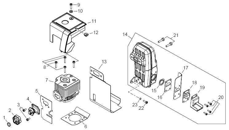
The muffler and exhaust system play a critical role in reducing noise and directing fumes away from the engine. This setup is designed to ensure smooth operation, minimizing the impact of harmful gases while keeping the noise levels down. Key Components: The exhaust system consists of several elements that work together to filter and expel gases efficiently. By channeling exhaust through a specific path, it enhances engine performance and reduces emissions. Maintenance: Regular inspection of the exhaust and muffler helps prevent blockages and ensures the system operates efficiently. Any damage or wear can affect both performance and safety. Clutch and Drive MechanismThe clutch and drive mechanism plays a crucial role in transferring power efficiently within the system. It ensures smooth operation by controlling the connection between the engine and the moving components, allowing for a seamless shift between idle and active states.
Detailed Look at Recoil Starter
The recoil starter is a crucial mechanism in many small gas-powered machines, ensuring a reliable way to ignite the engine manually. This component uses a simple pull-and-release mechanism, which engages the engine’s internal systems to initiate combustion and start the device. Understanding how the recoil starter functions can help with both regular maintenance and troubleshooting common issues.
Proper care of the recoil starter involves checking the pull cord for wear, ensuring the spring is in good condition, and occasionally lubricating the mechanism to prevent any jamming or stiffness. This structure and understanding of the recoil starter mechanism help users maintain their equipment more effectively, ensuring a longer operational lifespan. Fuel Tank and Cap ComponentsThe fuel system plays a crucial role in ensuring the smooth operation of equipment, allowing for efficient fuel storage and delivery. At the core of this system is the tank, which securely holds the fuel, and the cap, designed to maintain optimal pressure and prevent leaks. Main Features of the TankThe tank is built with durability in mind, designed to withstand the stresses of use. It ensures that the fuel is stored safely, providing a stable supply when needed. Its materials are chosen to prevent corrosion and to ensure longevity. Importance of a Well-Sealed CapThe cap is an essential component, as it provides a tight seal that keeps the fuel contained while also managing the internal pressure. Without a proper seal, leaks could occur, leading to inefficiency or potential hazards. Therefore, maintaining the integrity of the cap is critical to the fuel system’s overall function. Throttle Control and Cable MechanismThe throttle control and its associated cable system play a crucial role in regulating the engine’s performance and responsiveness. This mechanism is designed to ensure a smooth and efficient operation, allowing users to adjust the power output as needed during various tasks. In essence, the throttle control acts as the interface between the user and the engine, facilitating precise adjustments. When the operator engages the throttle lever, it transmits a signal through the cable, prompting the engine to increase or decrease power. This interaction not only enhances control but also contributes to the overall efficiency of the equipment. Maintaining this system is vital for optimal functionality. Regular inspections can help identify any wear or damage to the cable or control unit, ensuring that adjustments remain responsive and effective. A well-functioning throttle control mechanism is key to achieving desired results while using the equipment. Maintenance Tips for Ryobi BP42 PartsProper upkeep of your equipment is essential for optimal performance and longevity. Regular maintenance ensures that all components operate smoothly and reduces the risk of unexpected breakdowns. By following a few simple guidelines, you can keep your machine running efficiently and effectively. Start by regularly inspecting all elements for wear and tear. Look for signs of damage, such as cracks or corrosion, and address any issues promptly. Cleaning the various parts after each use helps prevent debris buildup, which can impair functionality. Ensure that lubrication is applied to moving components as needed to minimize friction and enhance performance. Additionally, consult the user manual for specific maintenance intervals and recommendations. Keeping a log of service dates and actions taken can help track the condition of your equipment over time. By being proactive in maintenance, you can extend the life of your machinery and ensure it remains in top-notch condition. |
