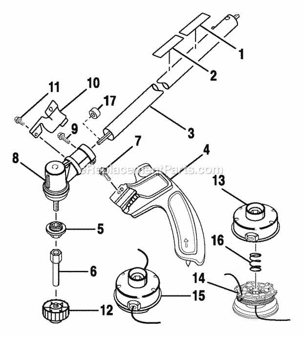
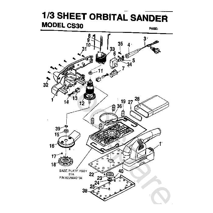
Ryobi CS30 Parts Breakdown Guide
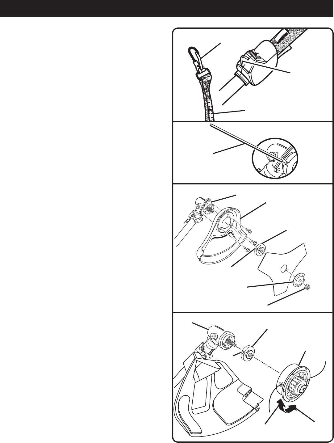
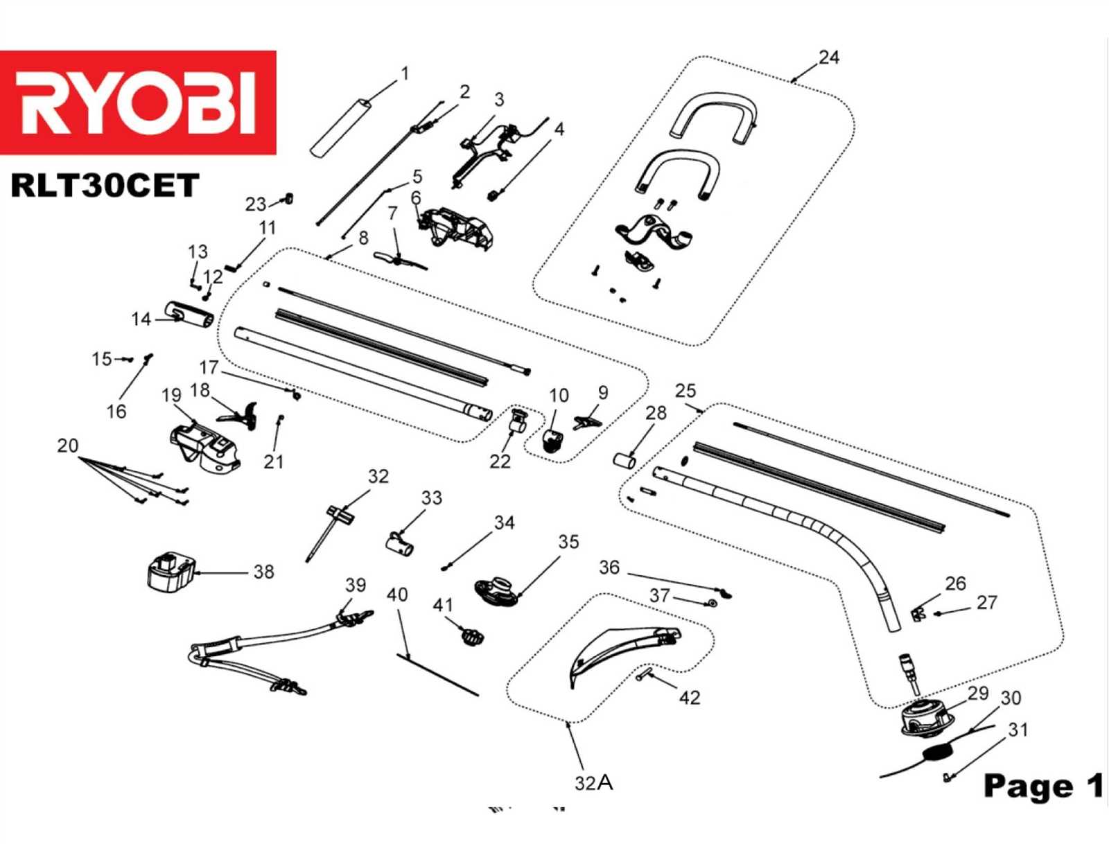
The arrangement of various elements in mechanical equipment plays a vital role in ensuring smooth operation and maintenance. Understanding how each element fits within the whole system is essential for efficient functioning and quick troubleshooting.
With a detailed illustration of individual components, users can easily identify and access different sections, allowing for accurate repairs and replacements. Such visual guides are indispensable for maintaining long-term durability and preventing potential malfunctions.
Regular upkeep and timely intervention are greatly simplified when users have a clear understanding of the internal structure of their equipment. This knowledge empowers them to take proactive measures and ensures that each piece is functioning at its optimal level.
Ryobi CS30: Comprehensive Parts Overview
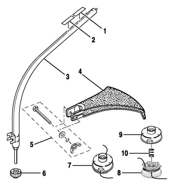
Understanding the components of this tool helps ensure smooth operation and longer durability. With a well-structured assembly of elements, each plays a critical role in the overall functionality. By familiarizing yourself with the individual sections, you can make maintenance easier and prevent common issues.
- Power Source System: The engine unit delivers the required energy for performance, maintaining balance between power and efficiency.
- Cutting Mechanism: Includes essential blades and chains that handle the core function of cutting, ensuring precise results.
- Control and Handle Unit: Offers ergonomic support, allowing for better grip and ease of maneuvering during use.
- Safety Features: Protects users by incorporating automatic stop features and protective guards to minimize risks.
- Fuel and Lubrication System: Ensures proper fuel flow and lubrication to enhance the machine’s lifespan and performance.
Engine Components Breakdown
The engine is composed of various crucial elements that work together to ensure smooth operation and efficiency. Understanding the role of each component helps in maintaining optimal performance and diagnosing potential issues.
Main Structural Elements
The core structure includes key elements responsible for housing and supporting the internal mechanisms. These elements not only provide stability but also ensure the proper alignment of moving parts, which is vital for smooth functionality.
Internal Moving Parts
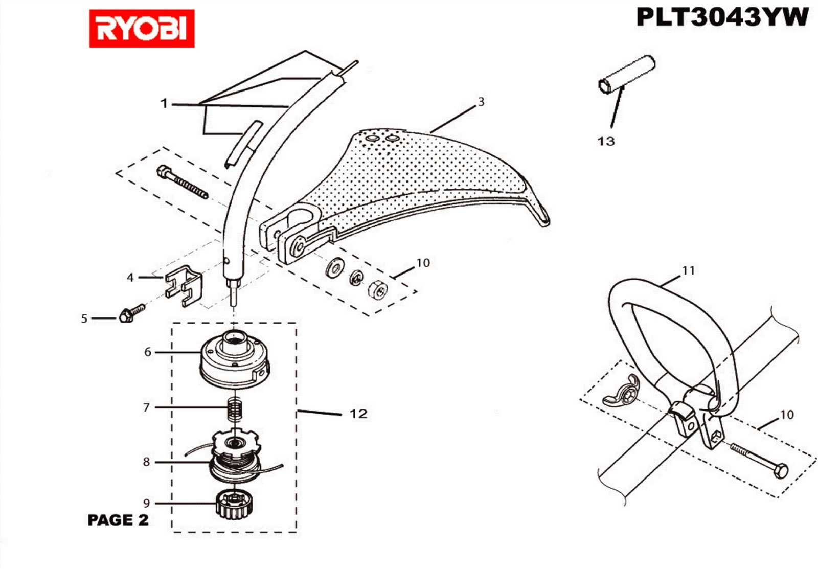
Within the engine, several components are in constant motion, working in harmony to generate power. These parts must withstand high temperatures and friction, making their durability and precision critical to the overall performance.
| Component | Function |
|---|---|
| Cylinder | Houses the piston and facilitates combustion. |
| Piston | Transfers energy from combustion to the crankshaft. |
| Crankshaft | Converts the piston’s linear motion into rotational motion. |
| Connecting Rod | Links the piston to the crankshaft, enabling power transfer. |
Fuel System Parts and Functions
The fuel system ensures the consistent supply and distribution of fuel needed for engine operation. This system consists of several components that work together to deliver fuel efficiently while maintaining optimal engine performance. Understanding how these elements function is crucial for the proper maintenance and troubleshooting of the system.
Main Components Overview
The system involves various essential elements, including the fuel tank, lines, and mechanisms responsible for controlling the flow of fuel. Each component plays a significant role in ensuring that fuel is delivered from the tank to the engine in a controlled and efficient manner.
Key Functions of the Fuel System
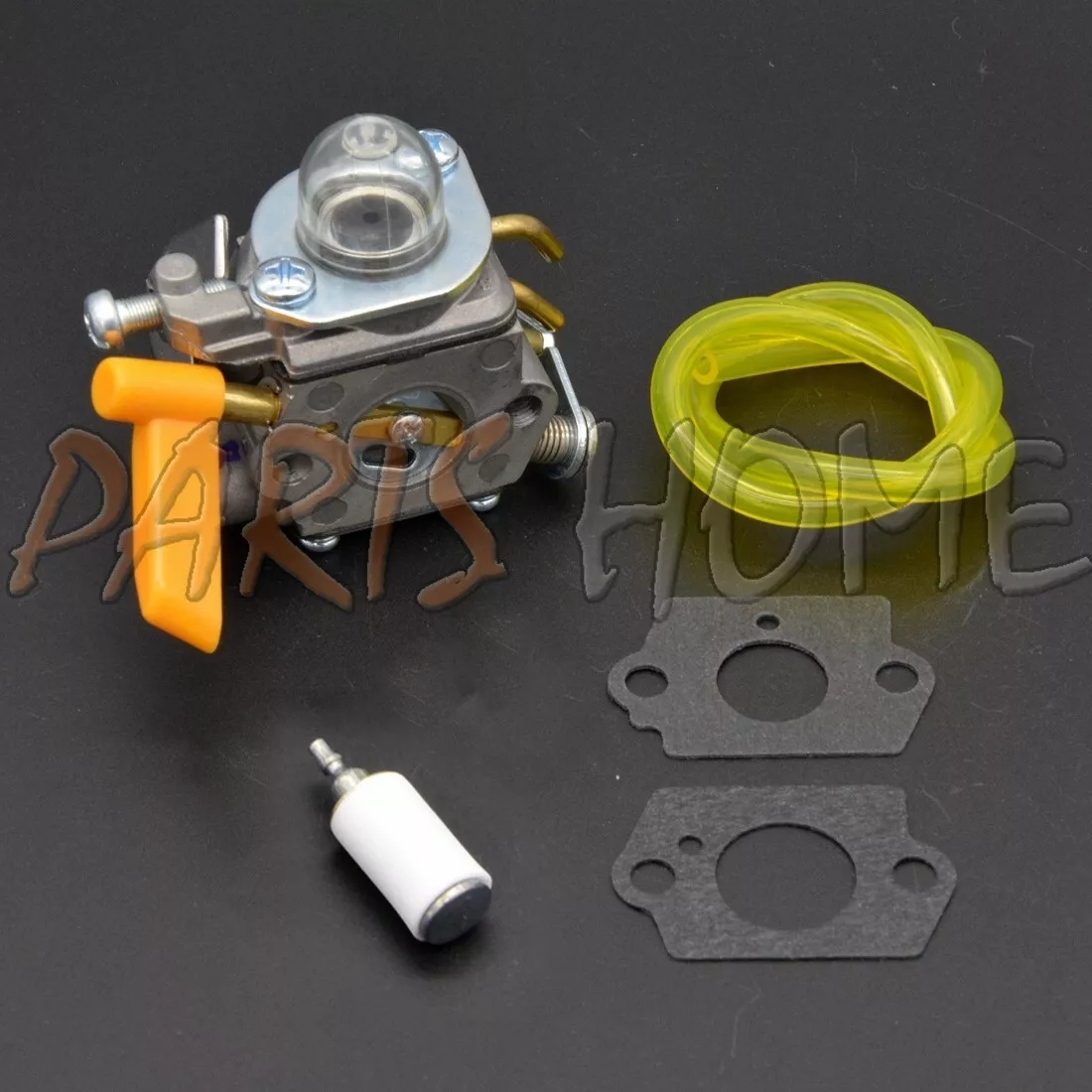
Each part of the system is designed to serve a specific purpose, from storing fuel to regulating its flow. Proper functioning of these components is vital for achieving smooth engine performance and preventing malfunctions during operation.
| Component | Function |
|---|---|
| Fuel Tank | Stores the necessary fuel for the engine. |
| Fuel Lines | Carry fuel from the tank to other system components. |
| Fuel Filter | Removes impurities to prevent blockages. |
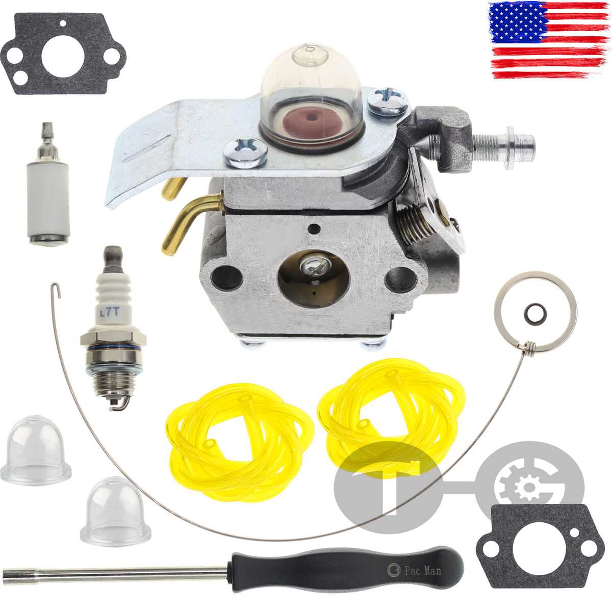
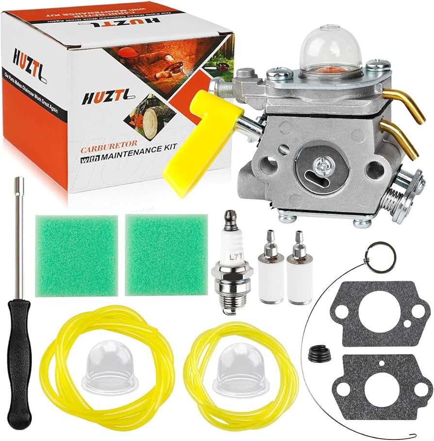
Carburetor
Starter Mechanism and Key Elements
The starter system in small engines plays a crucial role in initiating the engine’s operation. It is designed to engage the engine’s internal components, allowing for smooth ignition and efficient performance. Understanding the various components involved in this process is key to ensuring proper function and maintenance. Main Components
The mechanism includes essential elements such as the pull cord, which initiates motion, the recoil spring that resets the system, and the flywheel, which helps in transferring energy. Each of these components works in harmony to start the engine effectively and reliably. Common Issues and Maintenance TipsOver time, wear and tear on these parts can lead to starting problems. Regular inspection of the cord for fraying, ensuring the spring maintains its tension, and checking the flywheel for any damage can help in prolonging the lifespan of the starter mechanism. Ignition System Parts and LayoutThe ignition system is a crucial component responsible for ensuring efficient engine start-up and operation. Its layout consists of several interconnected elements that work together to generate and distribute the necessary spark for combustion. Understanding how these elements are positioned and how they interact is vital for maintaining engine performance and diagnosing potential issues. One of the key components includes the ignition coil, which converts low voltage from the power source into the high voltage required to ignite the fuel-air mixture. Additionally, the flywheel plays an important role in triggering the spark, thanks to its magnetic properties. These components must be properly aligned to ensure the system functions smoothly. Regular maintenance and checks on these elements can prevent malfunctions and prolong the lifespan of the engine. A clear understanding of the system’s layout can help in identifying wear or damage, allowing for timely repairs and ensuring optimal operation. Handle Assembly and Related Parts
The handle assembly is a crucial component in any equipment, providing the necessary support and control during operation. This section delves into the various elements that make up this assembly, highlighting their functions and interrelationships. Understanding the components of the handle assembly can enhance your ability to troubleshoot and maintain your equipment effectively. Below are key elements associated with the handle assembly:
Proper maintenance of these components ensures optimal performance and longevity of the equipment. Regular inspection and timely replacement of worn-out parts are recommended to prevent operational issues. Air Filter Components and Maintenance
The air filtration system is crucial for ensuring optimal performance and longevity of equipment. Regular upkeep and understanding its components can prevent inefficiencies and potential damage. This section provides insights into the various elements of the air filter system and guidelines for effective maintenance. Key Components: The air filter assembly typically consists of several essential parts, including the filter element, housing, and any associated seals or gaskets. The filter element serves as the primary barrier against dirt and debris, while the housing protects the element and facilitates airflow. Proper sealing is vital to prevent unfiltered air from entering the system. Maintenance Tips: To maintain the effectiveness of the air filtration system, it is recommended to inspect and clean the filter regularly. Depending on usage conditions, the filter may need to be replaced periodically. Always consult the manufacturer’s recommendations for specific maintenance intervals and replacement procedures to ensure optimal operation. Chain and Blade System Diagram
The chain and blade assembly plays a crucial role in the efficient functioning of cutting equipment. Understanding the components and their arrangement is essential for maintenance and repair. This section will explore the essential elements that comprise this system, highlighting their interactions and importance. At the core of the assembly lies the blade, designed for optimal cutting performance. It is supported by a series of links forming the chain, which facilitates movement and enhances the cutting efficiency. The integration of these parts ensures smooth operation, allowing users to achieve precise results in various applications. Regular inspection of the chain and blade assembly is vital for longevity and performance. Identifying wear or damage early can prevent further complications and maintain the effectiveness of the equipment. Familiarity with the layout and functionality of these components will aid in effective troubleshooting and timely replacements. Exhaust System Overview for Ryobi CS30The exhaust system is a crucial component of any combustion engine, responsible for directing harmful gases away from the engine and ensuring optimal performance. Understanding its design and functionality is essential for maintaining efficiency and prolonging the life of the equipment. This section delves into the essential elements of the exhaust mechanism, highlighting its role in overall engine operation. Components of the Exhaust System
The exhaust assembly typically consists of several key parts, including the muffler, exhaust pipe, and various fittings that connect these elements. Each component works in tandem to effectively channel exhaust gases, minimizing noise and emissions while optimizing engine output. Importance of MaintenanceRegular upkeep of the exhaust system is vital for preventing blockages and ensuring that gases are expelled efficiently. Neglecting this system can lead to performance issues, increased emissions, and potential damage to the engine. Routine inspections and cleaning can significantly enhance functionality and longevity. Protective Covers and Shielding Elements
Protective coverings and shielding components play a vital role in enhancing the safety and durability of equipment. These elements are designed to prevent damage to sensitive parts and ensure optimal performance during operation. By utilizing robust materials, they help to safeguard against environmental factors, debris, and wear over time. Various types of covers and shields are available, each tailored to meet specific needs and requirements. Some are engineered to withstand high temperatures, while others are crafted to resist moisture and dust ingress. Proper installation and maintenance of these components are crucial for maintaining the integrity of the machinery and prolonging its lifespan. In addition to their protective functions, these elements also contribute to the overall aesthetic appeal of the equipment. A well-designed cover not only enhances functionality but can also improve the appearance, making it an integral part of the overall design. Regular inspections and timely replacements of worn-out components are essential to ensure continued efficiency and safety. Clutch and Drive System Details
The clutch and drive system plays a crucial role in the overall functionality of a cutting tool, ensuring efficient power transfer from the motor to the blade. This mechanism is designed to engage and disengage seamlessly, allowing for optimal performance during operation and providing safety features to prevent overload. Components of the Clutch Mechanism
Key elements of the clutch mechanism include the clutch assembly, which consists of springs, shoes, and a housing that work together to manage torque delivery. The design ensures that the clutch engages under load, providing the necessary grip for effective cutting while minimizing wear and tear during idle periods. Drive System Functionality
The drive system is responsible for converting rotational motion into linear movement, allowing the cutting tool to perform its intended tasks. This system includes gears, belts, or direct drives that synchronize with the clutch to optimize efficiency. Proper maintenance of these components is essential to ensure longevity and reliable performance. |

