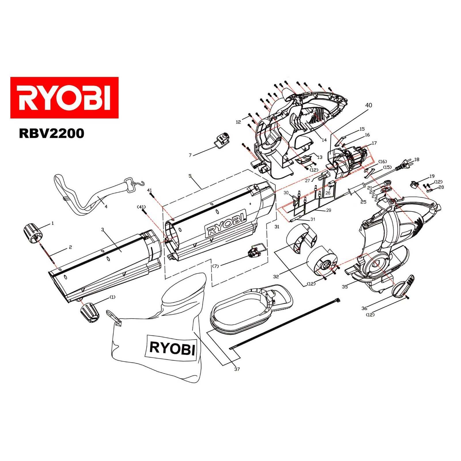
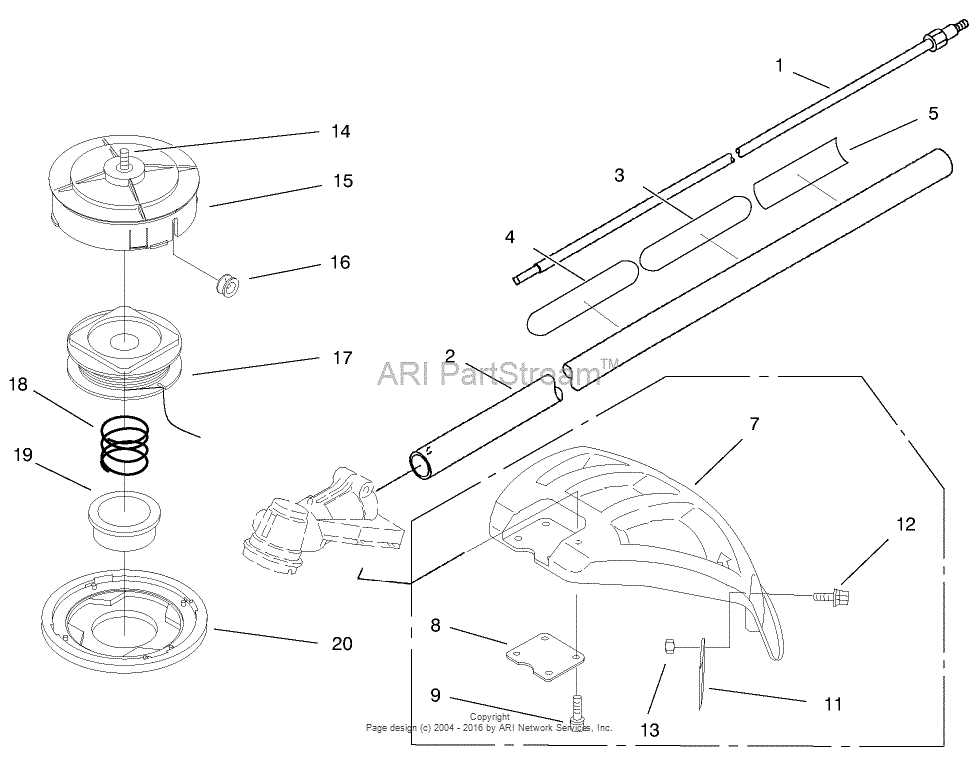
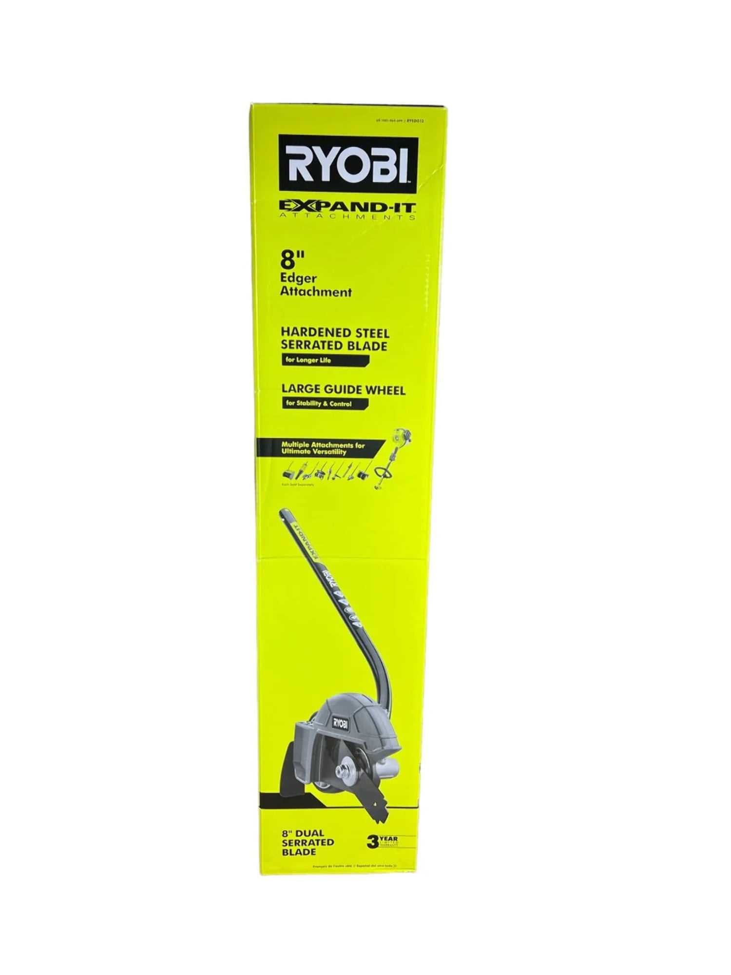
Ryobi P2200 Parts Breakdown
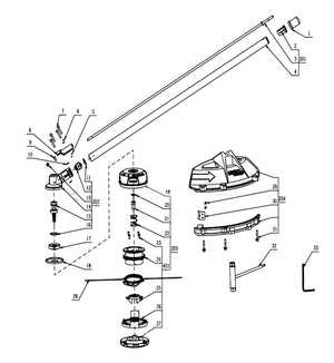
Understanding the layout of essential elements in any device can significantly improve the efficiency of its maintenance and repair. When you’re familiar with how the various mechanisms interact, troubleshooting becomes more straightforward, and the overall upkeep process is simplified. Whether you’re looking to replace specific elements or simply inspect the system, having a clear view of the internal structure is invaluable.
To fully grasp the functionality of a complex machine, a visual breakdown of its mechanisms is often necessary. Each section plays a critical role in ensuring smooth operation, and recognizing the placement and function of every component can help in performing precise repairs. This structured guide will offer clarity and a deeper und
Understanding the Ryobi P2200 Structure
The design of this tool revolves around a carefully constructed system of components that work in unison to deliver effective performance. Its assembly ensures durability while maintaining ease of use, allowing users to efficiently tackle a variety of tasks. This section delves into the core framework of the device, breaking down the various elements that come together to create its robust build.
Key Functional Sections
To fully understand the operational mechanism, it is important to recognize the main segments. These include the driving system, which powers the tool, and the control panel, where settings are adjusted. Each section serves a distinct purpose, contributing to the overall efficiency and precision.
Core Components and Their Roles
| Component | Function | ||||||||||||||||||||||||||||||||||||
|---|---|---|---|---|---|---|---|---|---|---|---|---|---|---|---|---|---|---|---|---|---|---|---|---|---|---|---|---|---|---|---|---|---|---|---|---|---|
| Power Unit | Provides the energy required for operation | ||||||||||||||||||||||||||||||||||||
| Blades |
| Component | Description |
|---|---|
| Blade Material | High-carbon steel or tungsten carbide for durability and sharpness. |
| Blade Design | Different shapes and teeth configurations for specific cutting tasks. |
| Cutting Angle | Optimized angles to enhance cutting efficiency and reduce effort. |
| Drive Mechanism | Engages the blade through pulleys and belts to ensure smooth operation. |
| Safety Features | Guards and automatic shut-off systems to protect the user during operation. |
Battery Connections and Power Flow
This section explores the intricate network of connections that facilitate energy transfer within portable devices. Understanding how electrical components interrelate is crucial for optimal performance and efficiency. The flow of power is essential for ensuring that the unit operates reliably and effectively under various conditions.
Connection Types
There are several types of connections utilized in portable power systems. Wired connections are commonly employed for direct power transfer, while wireless options offer greater flexibility and ease of use. Each connection type plays a vital role in maintaining a consistent flow of energy, which is necessary for the device’s operation.
Power Flow Dynamics
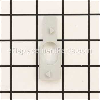
The dynamics of power flow involve several key factors, including voltage levels, current ratings, and overall energy efficiency. Understanding these parameters allows users to optimize the performance of their devices. Proper management of these elements ensures that energy is utilized effectively, prolonging battery life and enhancing overall functionality.
Exploring the Handle and Control System
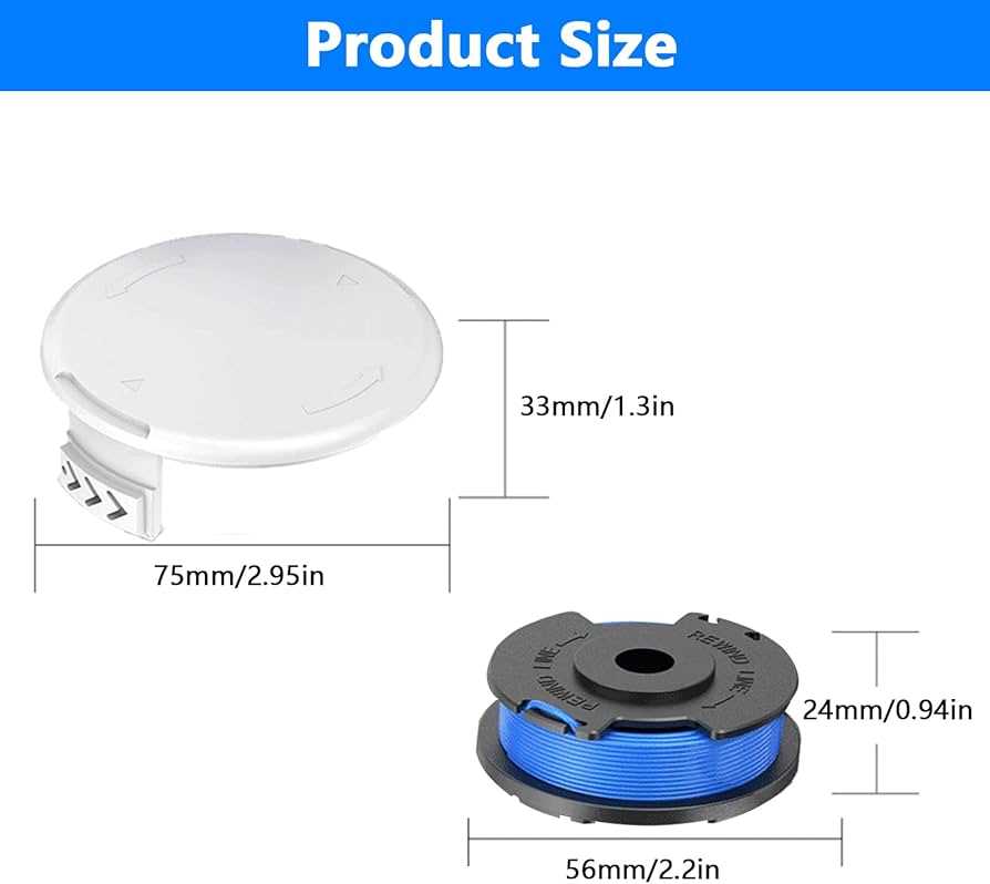
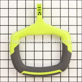
The handle and control mechanism plays a crucial role in ensuring user comfort and operational efficiency. This section delves into the design and functionality of these components, emphasizing their importance in facilitating seamless interaction with the device.
Ergonomics is a key consideration in the design of the handle. It is crafted to fit naturally in the user’s grip, reducing fatigue during prolonged use. This thoughtful approach enhances the overall experience, allowing for better maneuverability and control.
The control system comprises various buttons and switches, strategically placed for easy access. Each element is designed to respond intuitively to user inputs, ensuring that adjustments can be made swiftly without disrupting workflow. Understanding this layout is essential for maximizing efficiency and safety during operation.
Additionally, the integration of safety features within the handle and control system is paramount. These features not only protect the user but also enhance confidence in the tool’s reliability. This aspect highlights the ultimate importance of a well-designed interface in any operational device.
Detailed Look at the Safety Features
Understanding the safety mechanisms integrated into power tools is essential for ensuring user protection during operation. These features not only mitigate risks but also enhance the overall user experience by promoting confidence while using the equipment.
Key Safety Mechanisms
Several critical safety elements contribute to the secure operation of tools. Here is an overview of these mechanisms:
| Safety Feature | Description |
|---|---|
| Guarding Systems | Physical barriers that prevent accidental contact with moving parts. |
| Emergency Shut-Off | Instantly halts operation when activated, reducing the risk of injury. |
| Safety Switches | Require deliberate action to engage, preventing unintentional starts. |
| Overload Protection | Automatically stops the tool to prevent damage and overheating. |
User Guidelines for Safety
Alongside built-in features, following recommended practices is crucial for maximizing safety. Proper training, wearing protective gear, and regular maintenance are vital components that ensure a safe working environment.
How the Exhaust System Operates
The exhaust mechanism plays a crucial role in the efficient functioning of various machines, particularly those powered by internal combustion engines. Its primary purpose is to manage the gases produced during the combustion process, ensuring optimal performance and minimizing harmful emissions.
Key Components of the Exhaust System
- Exhaust Manifold: Collects gases from the engine’s cylinders and directs them into the exhaust piping.
- Catalytic Converter: Reduces harmful pollutants through chemical reactions, converting them into less harmful substances.
- Silencer: Reduces noise generated by the escaping gases, creating a more pleasant operating environment.
- Exhaust Pipe: Transports the gases from the engine out into the atmosphere.
How Gases Flow Through the System
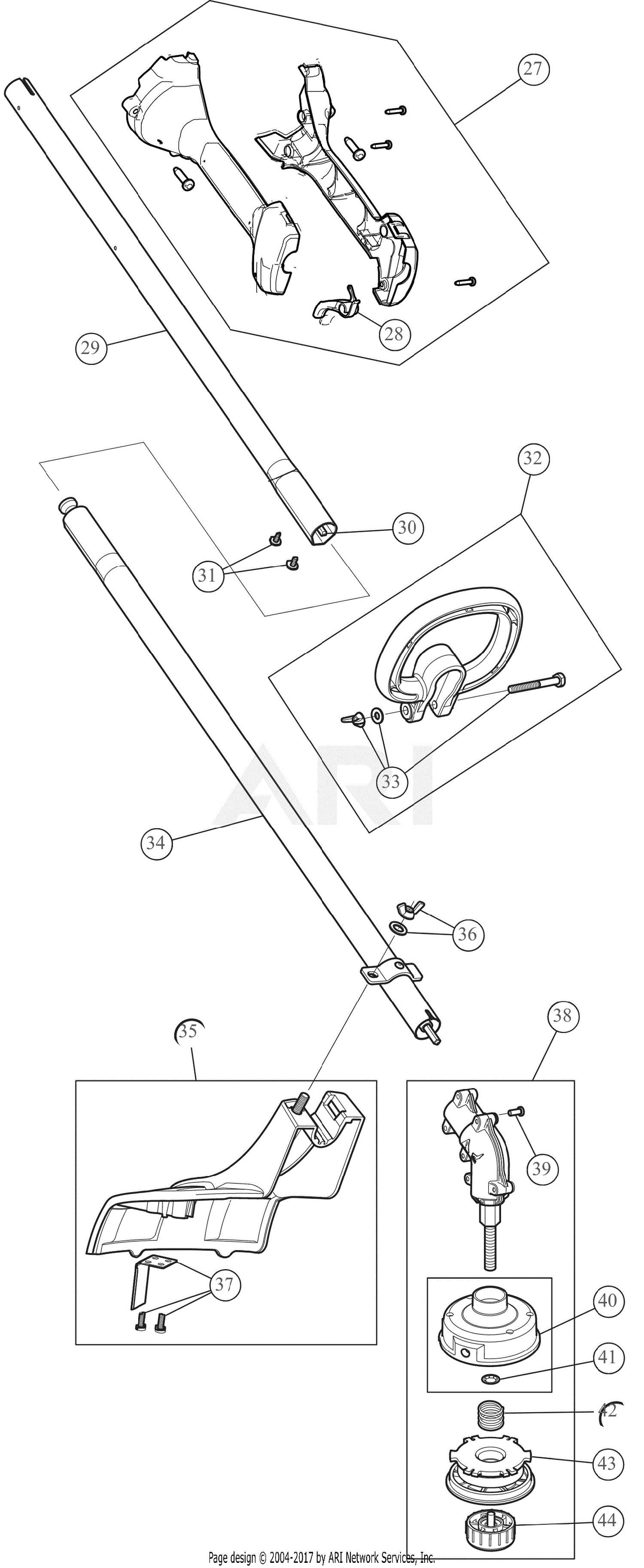
- The engine burns fuel, producing exhaust gases.
- Gases are expelled into the exhaust manifold, which collects them from multiple cylinders.
- The gases travel through the catalytic converter, where pollutants are neutralized.
- Next, they pass through the silencer, which minimizes noise.
- Finally, the gases exit through the exhaust pipe, releasing them into the atmosphere.
Transmission and Gearbox Overview
The transmission and gearbox are essential components in many mechanical systems, playing a crucial role in the transfer of power from the engine to the working parts of the machine. These systems are designed to efficiently manage speed and torque, enabling optimal performance under varying operational conditions.
Within the gearbox, a series of gears interact to provide different gear ratios. This allows for adjustments in rotational speed and torque, which are vital for adapting to different tasks. A well-engineered gearbox ensures smooth transitions between gears, minimizing wear and tear while enhancing efficiency.
Types of Gear Systems include spur, helical, and bevel gears, each offering unique benefits. Spur gears are straightforward and reliable, while helical gears provide quieter operation and improved load capacity. Bevel gears, on the other hand, are ideal for changing the direction of power transmission.
Maintenance of the transmission and gearbox is critical for longevity. Regular inspections, lubrication, and timely replacement of worn components can prevent costly breakdowns and ensure sustained performance.
Inspecting the Drive Shaft Components
The drive shaft is a critical element in any machinery, facilitating the transfer of power and ensuring smooth operation. Regular examination of its components is essential for maintaining optimal performance and longevity. This section outlines key aspects to consider when assessing these vital parts.
| Component | Function | Inspection Tips |
|---|---|---|
| Drive Shaft | Transmits power from the engine to the mechanism | Check for bends or cracks; ensure it rotates freely |
| U-Joints | Allows flexibility and motion between segments | Look for wear or play; lubricate as necessary |
| Bearings | Supports the shaft and reduces friction | Inspect for smooth rotation; listen for unusual noises |
| Couplings | Connects two shafts and accommodates misalignment | Check for damage or excessive wear; replace if necessary |
Maintenance of the Ryobi P2200 Parts
Regular upkeep of equipment components is crucial for optimal performance and longevity. Ensuring that every element functions smoothly not only enhances efficiency but also prevents potential breakdowns. This section will outline essential practices to maintain various elements effectively, fostering a reliable operation.
Start by routinely inspecting all mechanical parts for signs of wear or damage. Pay attention to connections and fasteners, ensuring they are tight and free from corrosion. Clean surfaces regularly to remove dirt and debris, which can lead to overheating or hinder movement.
Lubrication is vital for maintaining moving elements. Use appropriate lubricants to reduce friction and wear, applying them according to manufacturer recommendations. This practice can significantly extend the life of critical components.
Finally, it’s important to store the equipment properly when not in use. Keeping it in a dry, sheltered location will protect it from environmental factors that could cause deterioration. By following these guidelines, you can ensure that your machinery remains in peak condition for years to come.
