Briggs and Stratton 5HP Engine Parts Diagram Guide
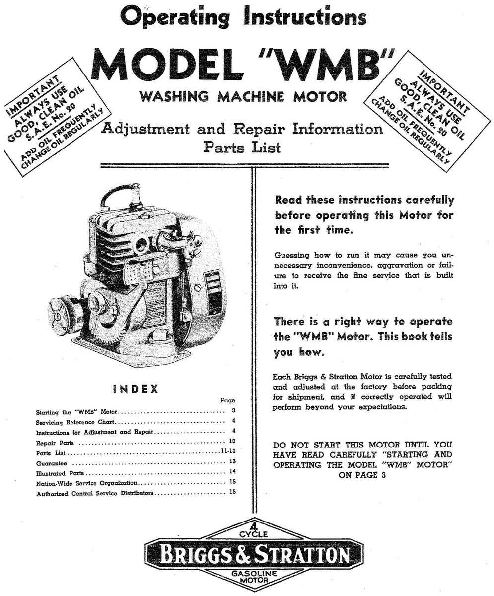
The inner workings of compact combustion systems rely on a variety of interconnected elements that ensure efficient performance. From ignition to fuel flow, each element plays a critical role in maintaining functionality. Understanding how these components fit together helps in keeping the system running smoothly over time.
Mechanical maintenance and timely replacements are essential for extending the lifespan of any small-scale power system. Whether you’re focusing on the carburetor, cooling mechanism, or ignition system, having a solid understanding of their structure can make a world of difference in performance and troubleshooting.
Detailed visual references often aid in identifying how various pieces are arranged within the system. By familiarizing yourself with these, you can simplify repairs, make modifications, or enhance efficiency without the need for expert help.
5hp Briggs and Stratton Engine Overview
This type of small motor is widely recognized for its reliability and versatility in powering various machines, from lawn mowers to generators. Known for delivering consistent performance, it’s often a popular choice for both homeowners and professionals alike. Its compact design, coupled with efficient fuel consumption, makes it ideal for small-scale applications where space and energy efficiency are important.
The motor features a simple yet robust structure, allowing for ease of maintenance and long-term durability. With proper care, this unit can provide years of dependable service, making it a valuable component in many mechanical systems.
Key Components of the Engine
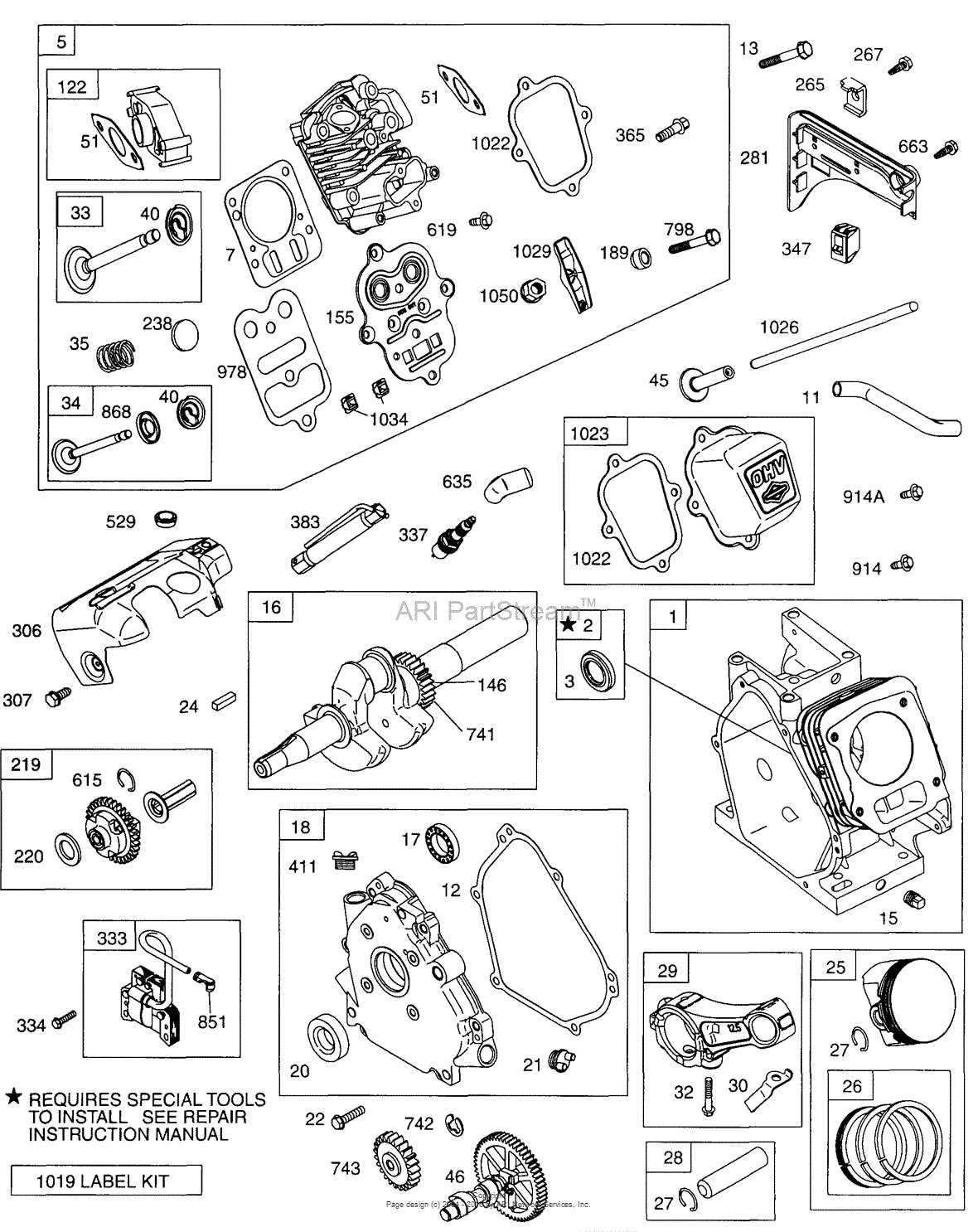
The inner workings of this motor system rely on various critical elements that collaborate to ensure smooth operation. Each piece has a unique role in maintaining functionality, from ignition to power output. Understanding these components can help in troubleshooting and optimizing performance.
Primary Mechanical Elements
- Piston: This element moves within the cylinder, generating the necessary force to power the machinery.
- Crankshaft: Converts the linear motion of the piston into rotational energy, driving the system.
- Connecting Rod: Links the piston to the crankshaft, transmitting motion between them.
Key Supportive Features
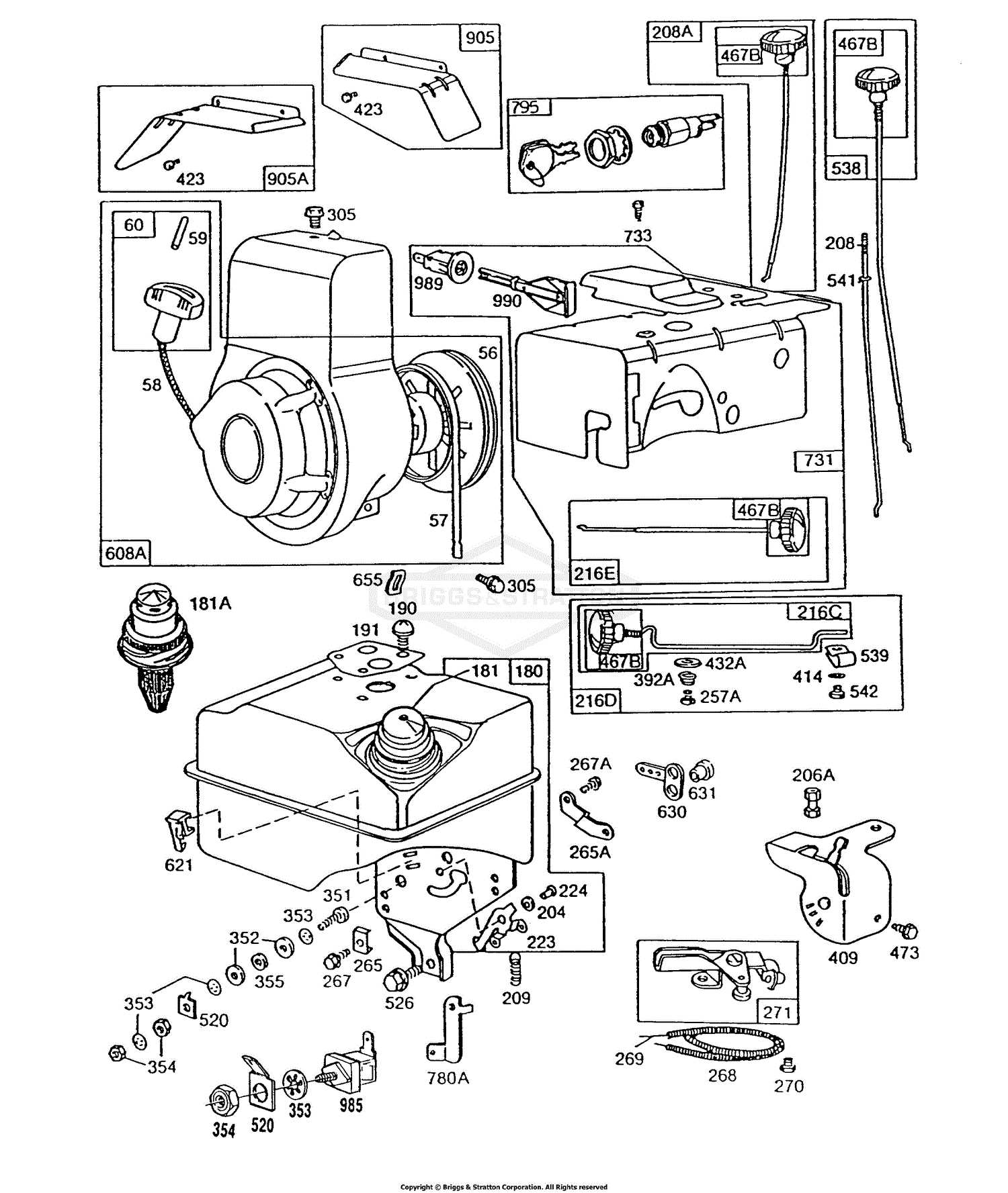
- Cylinder: Houses the piston and contains the combustion process.
- Valves: Control the intake of air and fuel, as well as the release of exhaust gases.
- How to Identify the Carburetor Parts
Understanding the key components of a carburetor is essential for maintaining its proper function. While each carburetor may have its own unique design, the basic elements remain consistent, making it easier to identify them. By recognizing these essential components, you can ensure efficient fuel delivery and overall performance.
Main Components of the Carburetor
The carburetor typically consists of several important sections. One of the most critical is the float chamber, which regulates the fuel level. The throttle controls the airflow, directly impacting the speed. Another key section is the choke, which adjusts the fuel mixture, especially during cold starts.
Recognizing Smaller Elements
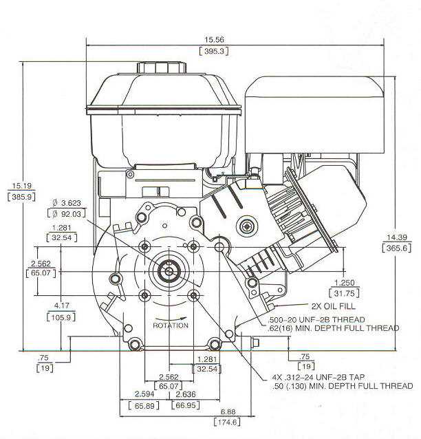
In addition to the larger parts, there are smaller but equally important pieces, such as the jets that control fuel flow. The needle valve is responsible for maintaining the proper fuel level, while the venturi creates the necessary pressure drop to draw fuel into the airflow. Identifying these small yet crucial components is key to troubleshooting and repairs.
Understanding the Fuel System Layout
The fuel system is essential for ensuring smooth and efficient operation of any combustion device. It involves a series of interconnected components that work together to deliver fuel to the core mechanism, enabling the production of power. A thorough understanding of this layout can help in diagnosing issues and optimizing performance.
Key Components of the Fuel System
The primary elements include a fuel tank, which stores the gasoline, and a carburetor, responsible for mixing fuel with air. The system also consists of fuel lines that transport the gasoline from the tank to the carburetor, and a fuel filter that removes impurities, ensuring clean delivery. Each part plays a critical role in maintaining the functionality of the device.
Maintaining the Fuel System
Regular maintenance is crucial for the longevity of the fuel system. Ensuring that fuel filters are replaced and fuel lines are clear of blockages will help the overall efficiency. Periodically cleaning the carburetor also prevents buildup that could affect the fuel-air mixture. Attention to these aspects ensures smooth operation and prolongs the life of the entire system.
Examining the Ignition System Elements
The ignition mechanism is vital to ensuring smooth operation and reliability. Each component plays a significant role in creating the necessary spark to start and sustain the power cycle. Understanding the individual elements of this system helps diagnose potential issues and maintain optimal performance.
Key Components of the Ignition Mechanism
- Spark Plug: Responsible for delivering the electric spark that ignites the fuel-air mixture.
- Ignition Coil: Converts low voltage into the high voltage required to create the spark.
- Flywheel: Contains magnets that generate an electrical charge, working with the coil to produce energy.
- Contact Points: Regulate the timing of the spark by opening and closing at precise intervals.
How Each Element Contributes to Ignition
Each
Crankshaft and Piston Assembly Breakdown
The assembly of the crankshaft and piston plays a vital role in the functionality of a small combustion unit. This section delves into the intricate components that work together to convert linear motion into rotational energy, ensuring smooth operation and efficiency.
Crankshaft serves as the heart of this assembly, providing the necessary rotation to drive various mechanisms within the unit. Its durability and precision are critical, as it must withstand significant forces during operation. Typically constructed from high-strength materials, the crankshaft is designed to maintain integrity under stress.
On the other hand, the piston is responsible for creating the compression needed for combustion. Its movement within the cylinder generates the power that drives the crankshaft. Proper fit and alignment between the piston and the cylinder wall are essential for optimal performance, preventing issues such as wear and leakage.
Understanding the interaction between these components can aid in troubleshooting and maintenance, enhancing the longevity and reliability of the entire system. Regular inspection of the crankshaft and piston assembly ensures that any potential issues are identified early, allowing for timely repairs and adjustments.
Air Filter Housing and Connections
The air filter housing plays a crucial role in maintaining the efficiency and performance of a small motor. It serves as a protective enclosure for the filter, ensuring that only clean air enters the combustion chamber. Proper connections and maintenance of this component are essential for optimal airflow and engine longevity.
Components of the Air Filter Housing
- Housing: This structure encases the air filter and provides stability.
- Cover: A lid that secures the filter in place, preventing dirt ingress.
- Sealing Gasket: Ensures an airtight fit between the housing and cover.
- Intake Duct: Connects the housing to the carburetor, directing airflow.
Importance of Proper Connections
Secure and precise connections are vital for the air filter housing. Loose or damaged fittings can lead to air leaks, compromising performance. Regular inspection and maintenance are recommended to ensure all components are intact and functioning correctly.
Fuel Tank Mounting and Structure
The mounting and structural design of the fuel reservoir is crucial for ensuring efficient operation and stability during use. Proper placement and secure fastening prevent leaks and vibrations that can disrupt performance.
Typically, the fuel tank is affixed to the frame with durable brackets, allowing for easy access and maintenance. Materials used in construction often include high-quality plastics or metals, selected for their resistance to corrosion and ability to withstand various environmental conditions.
Additionally, the structure is designed to accommodate expansion and contraction caused by temperature fluctuations, which is essential for maintaining integrity over time. Adequate ventilation is also a key feature, preventing pressure buildup that could lead to hazardous situations.
Exhaust System Components Explained
The exhaust system is a crucial part of any motorized machinery, responsible for directing waste gases away from the combustion chamber. Understanding its components is essential for maintaining optimal performance and ensuring the longevity of the equipment.
Exhaust Manifold: This component collects gases from the cylinders and directs them into the exhaust system. It is typically made from cast iron or stainless steel, offering durability and resistance to high temperatures.
Exhaust Pipe: The exhaust pipe transports the gases from the manifold to the muffler. It is designed to withstand heat and corrosion while maintaining an efficient flow of gases.
Muffler: The muffler reduces the noise produced by the escaping gases. It contains internal baffles and chambers that dissipate sound waves, allowing for a quieter operation.
Exhaust Gasket: This sealant is placed between the manifold and the engine block to prevent leaks. A good-quality gasket is essential for maintaining pressure and preventing exhaust gas from escaping.
Tailpipe: The tailpipe is the final section of the exhaust system, directing gases away from the vehicle. Its design can impact both performance and sound levels.
Cooling System and Fan Blade Details
The cooling mechanism of small combustion units is crucial for maintaining optimal performance and longevity. A well-designed cooling system helps dissipate heat generated during operation, ensuring that components remain within safe temperature limits. The fan blade plays a pivotal role in this process by circulating air and enhancing heat dissipation, thus preventing overheating.
Components of the Cooling System
Key elements of the cooling setup include the cooling fins, fan blades, and associated ducts. The fins are strategically placed around the cylinder to maximize surface area for heat exchange. Meanwhile, the fan blade is typically attached to the crankshaft, rotating to draw air through the cooling fins, thereby aiding in temperature regulation.
Fan Blade Specifications
Understanding the specifications of the fan blade is essential for maintenance and replacement. The blade’s design can influence airflow efficiency and cooling effectiveness. Below is a summary table of typical dimensions and features.
Dimension Specification Diameter 6 inches Material Polypropylene Blade Count 4 Rotation Speed 3600 RPM Gasket and Seal Placement in the Engine
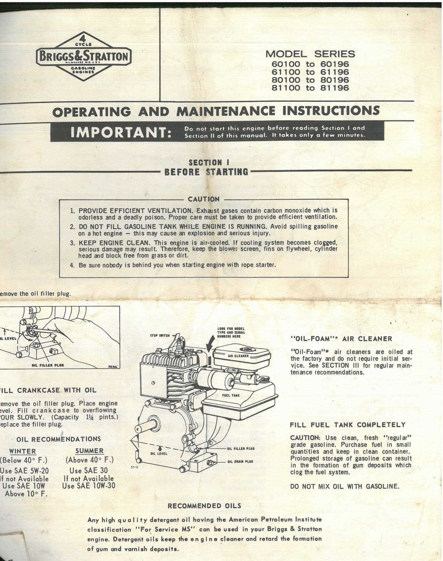
Proper positioning of gaskets and seals is crucial for maintaining optimal performance and preventing leaks. These components act as barriers, ensuring that fluids remain contained within the system while withstanding various pressures and temperatures.
Gaskets are typically installed between two mating surfaces, creating a tight seal that prevents the escape of liquids and gases. It is essential to ensure that these items are correctly aligned and seated to avoid potential leaks. Additionally, the surface condition plays a significant role; clean and flat surfaces promote better adhesion and sealing.
Seals, on the other hand, are often found around rotating shafts and moving parts. Their main function is to keep lubricants in while preventing contaminants from entering the system. When placing seals, it is important to consider the direction of the assembly, as well as any potential wear or damage that may occur over time. Regular inspection and replacement of these components can greatly enhance the longevity and efficiency of the machinery.
Starter Mechanism and Pull Cord Parts
The starter assembly plays a crucial role in initiating the operation of a small motor. This system is designed to facilitate the effortless engagement of the motor, enabling it to commence functioning without undue strain on the user. Within this mechanism, various components work in harmony to ensure reliability and efficiency.
Central to the starter mechanism is the pull cord, which, when tugged, activates the recoil starter. This component is responsible for retracting the cord and engaging the flywheel, allowing the engine to start. Additionally, the starter housing encases these parts, providing protection and ensuring smooth operation.
Other notable elements include the spring, which stores energy for the recoil action, and the cord guide, which helps maintain the correct alignment of the pull cord during operation. Each part is essential for the overall functionality of the starter assembly, ensuring a seamless start every time.
Governor Linkages and Adjustment Points
The efficiency of a small power unit heavily relies on the proper functioning of the governing mechanism. This system regulates the engine speed by adjusting the throttle based on load changes. Understanding the linkages involved in this process is essential for maintaining optimal performance.
Linkage Components play a crucial role in connecting the governor to the throttle control. These components must be properly aligned and free from wear to ensure smooth operation. Regular inspection of these linkages can prevent performance issues and enhance responsiveness.
Adjustment Points are strategically located within the governing assembly. Fine-tuning these points allows for precise control over engine speed, enabling better handling of varying loads. Familiarity with these adjustment locations aids in achieving desired performance levels.