Peerless Transaxle Components Diagram
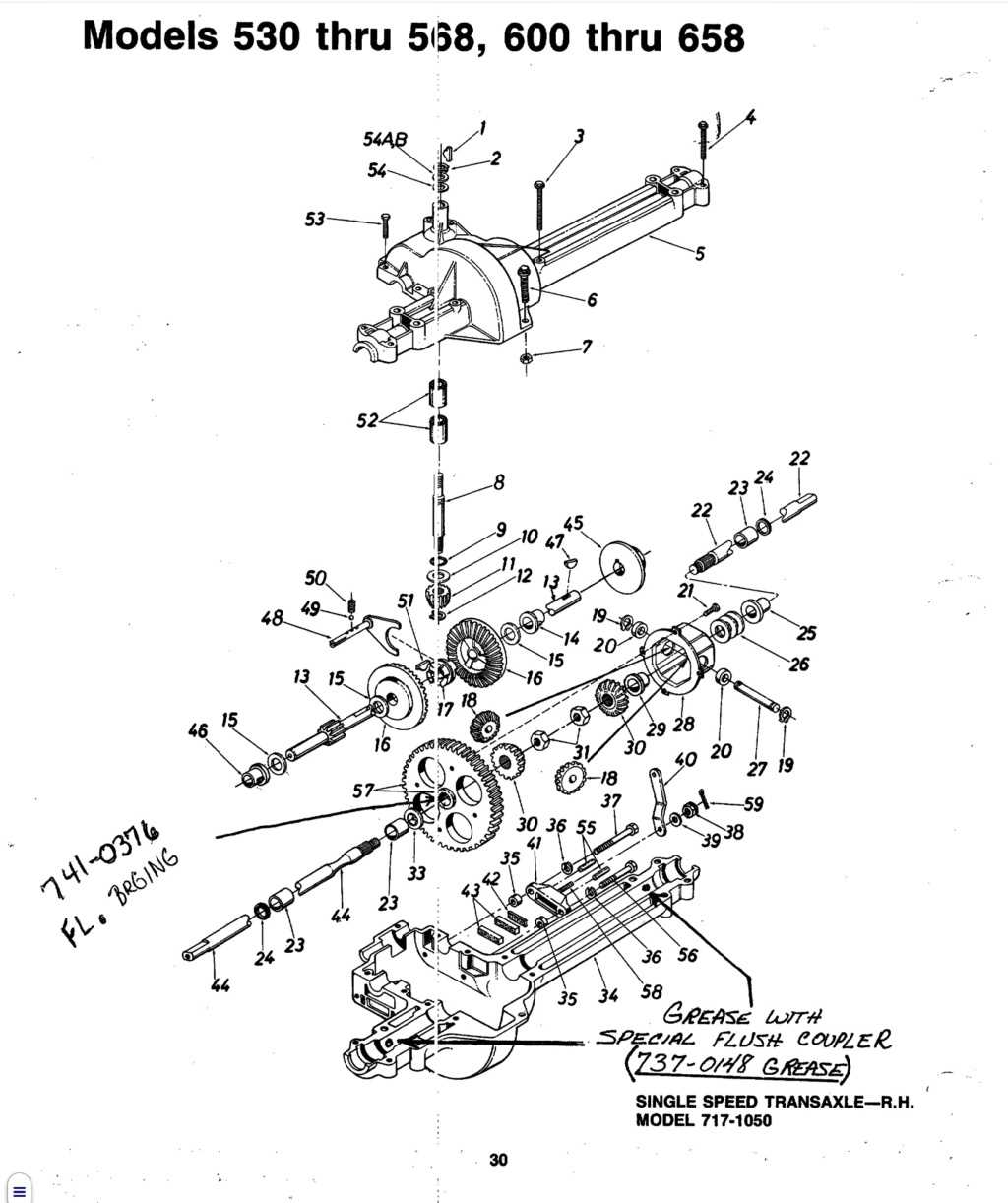
Understanding how intricate mechanical systems function requires careful attention to the various elements that contribute to their operation. Each unit is made up of numerous components, working together to ensure smooth and reliable performance. In this guide, we explore the essential structures that make up such systems, focusing on their roles and relationships within the mechanism.
The arrangement of these elements is key to efficient functionality. By examining the layout and connections, it becomes easier to troubleshoot issues, replace worn elements, and enhance performance. This comprehensive overview will help shed light on the complexities of these mechanical assemblies, providing insights into their internal structure and interactions.
Whether you are an enthusiast or a professional, gaining a deeper understanding of the inner workings of these systems is crucial for maintenance and optimization. Our exploration offers a detailed look into the essential parts, offering clarity on how they function as a cohesive whole.
Peerless Transaxle Parts Diagram Overview

Understanding the layout of mechanical components within complex assemblies is crucial for both maintenance and troubleshooting. By examining the structure of interconnected elements, one can gain insight into how the entire system operates smoothly. This overview aims to provide a clear representation of how various pieces fit together, ensuring functionality and performance.
Main Functional Sections
- Drive mechanism assembly: The central unit responsible for transmitting power and motion efficiently.
- Gear system: A set of interlocking pieces that manage speed adjustments and torque distribution.
- Housing unit: The protective shell that contains and supports the internal components.
Key Components Breakdown
- Input shaft: Transfers rotational force into the assembly.
- Bearings: Ensure smooth movement by reducing friction.
- Se
Understanding the Function of Key Components
In mechanical systems that involve motion transfer, each element plays a crucial role in ensuring proper functionality. By examining these essential elements, we can gain insights into how they contribute to the overall operation of the system. Understanding their purpose helps to maintain efficiency and ensure smooth performance under various conditions.
Each component is designed to handle specific tasks, whether it’s managing power distribution, ensuring stability, or reducing friction. By working together, these elements form an interconnected network, where even minor adjustments in one part can affect the performance of the entire system.
Dissecting the Inner Mechanisms of a Transaxle
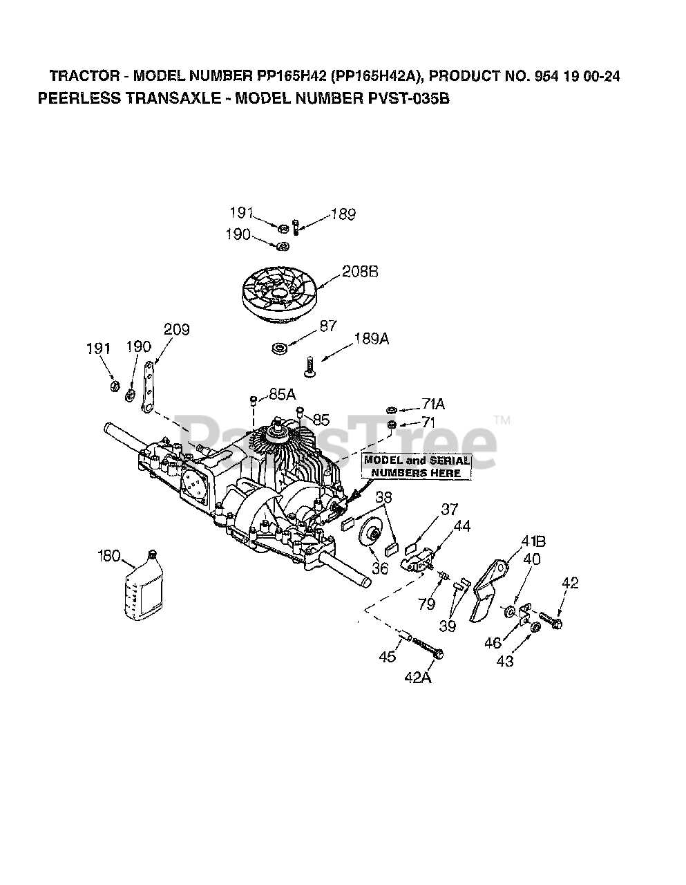
In mechanical systems where power distribution plays a key role, understanding the intricate network of components is essential. These assemblies are responsible for directing force efficiently, converting rotational energy, and ensuring smooth operation. Let’s break down how this complex unit functions internally.
- Power Transfer: The core function involves distributing energy from the power source to the wheels, ensuring proper movement and control.
- Gear Systems: Multiple gears work together to manage speed and torque, adjusting to different operating conditions.
- Clutch Mechanism: This element engages and disengages power flow, allowing for seamless transitions between driving modes.
- Lubrication Channels: A well-organized system of lubrication ensures minimal friction and heat buildup, contributing to the longevity of the system.
- Axle Components: The axle itself is central to the movement, enabling the wheels to rotate at varying speeds when necessary
How Gear Systems Operate within a Transaxle
Understanding how gear systems function in a compact drive mechanism is key to grasping the efficiency of power transmission. These mechanical assemblies enable the transfer of rotational motion and torque from one component to another, optimizing speed and force distribution. Let’s explore how these elements work together to ensure smooth operation.
- Input Shaft Rotation: The process begins with the input shaft, which transfers energy from the power source. This rotational force drives the gear system, initiating the movement of other components.
- Gear Interactions: Different-sized gears mesh together, altering speed and torque. Larger gears reduce speed while increasing torque, while smaller gears do the opposite, allowing for fine control of output.
- Output Shaft Function: After passing through the series of gears, the motion is transmitted to the output shaft. This shaft delivers the final movement to the connected wheels or machinery, driving forward the entire system.
The integration of gears ensures that the system operates efficiently, balancing power distribution and mechanical advantage across varying conditions. This design allows for smooth transitions between speed levels and torque output, essential for a
Identifying Essential Bearings and Seals
Understanding the critical components responsible for reducing friction and maintaining proper fluid separation is key in ensuring the longevity and efficiency of mechanical systems. Two such vital elements are bearings, which allow for smooth rotational movement, and seals, which prevent leakage of lubricants while keeping contaminants out. Proper identification of these components can significantly improve operational performance.
Main Types of Bearings
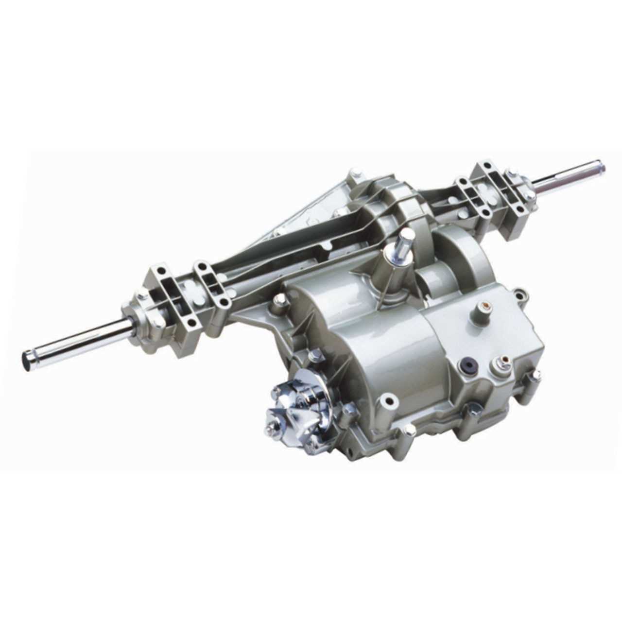
Bearings are designed to handle both radial and axial loads, and selecting the appropriate type is crucial. Below is an overview of common types and their key features:
Type of Bearing Key Features Ball Bearings Efficient for handling both radial and axial loads; commonly used in high-speed applications. Roller Bearings Designed Exploring Axle Shafts and Their Roles
In the realm of automotive engineering, the components that facilitate movement and support the vehicle’s weight play crucial roles in overall functionality. Among these elements, specific shafts stand out for their ability to transmit power from the engine to the wheels, ensuring smooth and efficient motion. Understanding these elements reveals their importance in the mechanics of transportation.
Functions of Axle Shafts
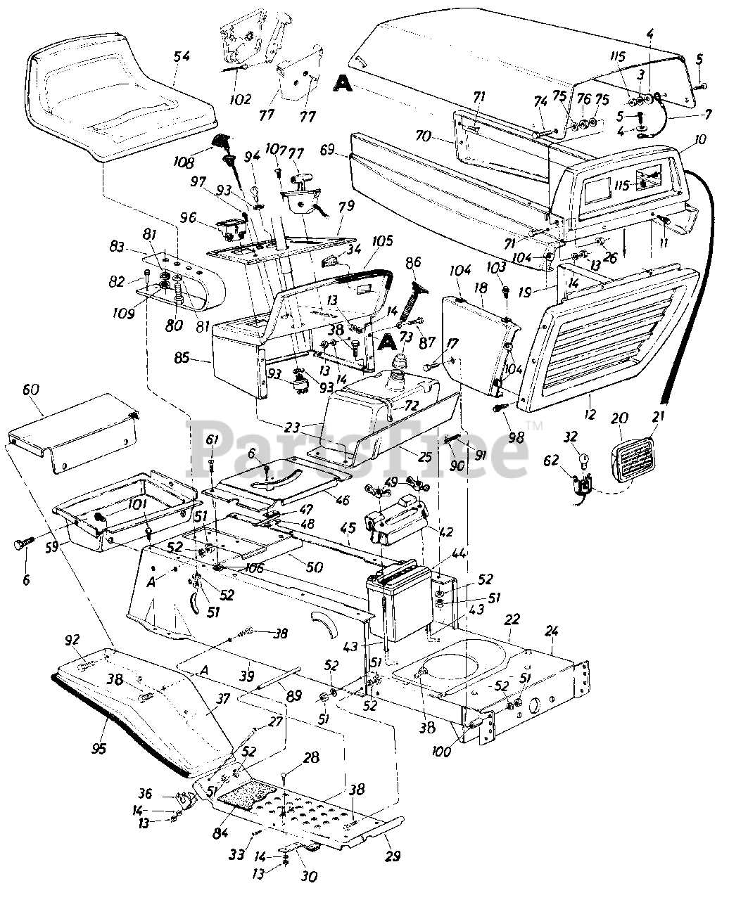
The primary duty of these shafts is to transfer rotational force from the drivetrain to the wheels. By doing so, they enable the vehicle to accelerate, decelerate, and maintain stability on various terrains. Moreover, these components are designed to withstand significant stress, contributing to the durability and reliability of the entire system.
Types and Variations
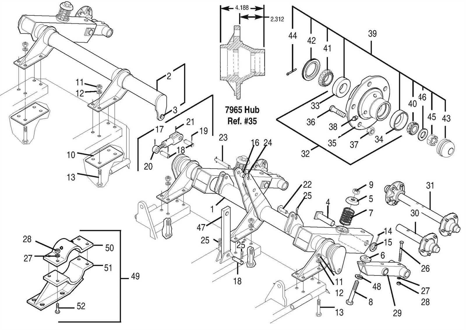
Different types of shafts are utilized depending on the design and purpose of the vehicle. For instance, some models incorporate solid shafts for enhanced strength, while others may use hollow versions to reduce weight without sacrificing performance. This variety allows for tailored solutions that meet specific engineering requirements, ensuring optimal functionality across diverse applications.
The Importance of Lubrication in Transaxle Systems
Proper maintenance of mechanical systems is crucial for their longevity and efficiency. One of the key elements in ensuring optimal performance is the application of suitable lubricants. These substances play a vital role in minimizing friction, preventing wear, and enhancing the overall functionality of the system. By understanding the significance of effective lubrication, users can make informed decisions regarding maintenance practices.
Effective lubrication not only reduces the friction between moving components but also helps in dissipating heat generated during operation. This thermal management is essential to prevent overheating, which can lead to premature failure of components. Moreover, lubricants create a protective barrier that shields internal surfaces from contaminants and corrosion, thereby prolonging the lifespan of the assembly.
Additionally, regular inspection and replacement of lubricants ensure that the system operates smoothly under varying loads and conditions. Using the correct type and viscosity of lubricant is paramount, as it directly influences the efficiency and reliability of the entire mechanism. By prioritizing lubrication, operators can significantly enhance performance and reduce maintenance costs.
Explaining Differential and Drive Components
The functionality of a vehicle’s motion relies heavily on a complex arrangement of mechanical elements. These components work in unison to ensure smooth and efficient transfer of power from the engine to the wheels. Understanding the role of each element within this system is crucial for both performance and maintenance.
Understanding the Differential
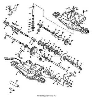
The differential serves a vital purpose in enabling the wheels to rotate at different speeds, particularly during turns. This mechanism allows for greater stability and control, facilitating smoother navigation through curves. By redistributing torque and allowing for independent wheel movement, the differential enhances traction and reduces tire wear.
The Role of Drive Components
Drive components encompass a variety of elements that contribute to the transmission of power. These include gears, shafts, and couplings, all designed to transfer motion efficiently. Each element must be precisely engineered to withstand varying loads and stresses, ensuring that energy is delivered effectively from the engine to the drive wheels. Regular inspection and maintenance of these components are essential for optimal performance.
Signs of Wear in Transaxle Parts
Identifying indicators of deterioration in mechanical components is crucial for maintaining optimal performance and ensuring longevity. Over time, various elements may exhibit signs that suggest they are no longer functioning at their best. Recognizing these symptoms early can prevent further damage and reduce repair costs.
Common Indicators of Deterioration
- Unusual Noises: Grinding, whining, or clunking sounds during operation may signify internal issues.
- Fluid Leaks: Puddles or stains underneath the vehicle could indicate leaking seals or gaskets.
- Increased Vibration: Excessive shaking while driving may point to imbalances or misalignment in components.
- Slipping Gears: Difficulty in maintaining gear engagement can be a sign of worn clutches or bands.
- Overheating: Elevated temperatures during operation often suggest fluid deficiencies or blockages.
Visual Signs to Inspect
- Check for surface cracks or deformation on critical components.
- Look for excessive wear patterns on friction surfaces.
- Inspect seals and gaskets for signs of deterioration or brittleness.
- Evaluate the condition of bearings for any signs of discoloration or pitting.
Proper Maintenance for Longevity of Parts
Ensuring the extended lifespan of mechanical components requires consistent care and attention. Regular maintenance not only enhances performance but also prevents costly replacements in the future. By implementing a systematic approach to upkeep, users can significantly extend the functionality of their equipment.
Routine Inspections
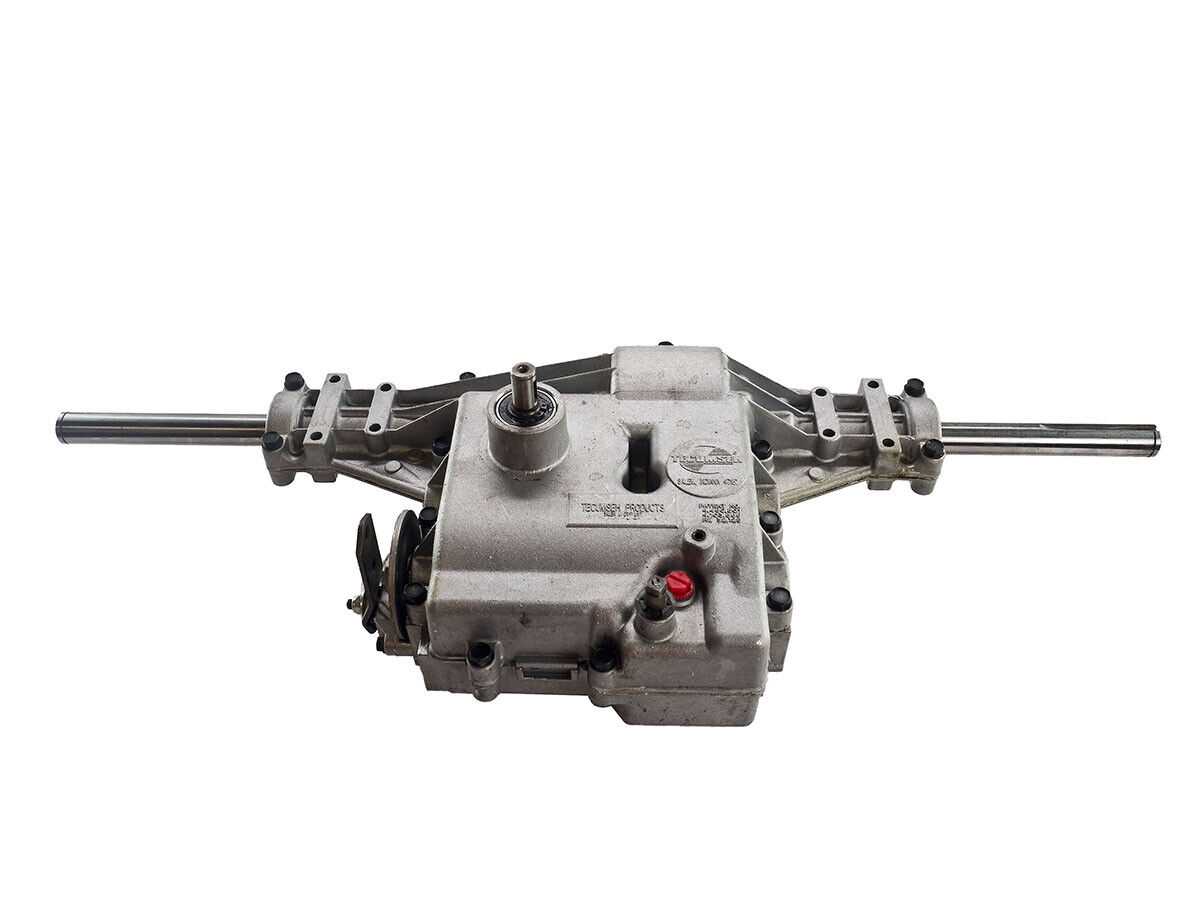
Conducting frequent examinations of the machinery is crucial for identifying wear and tear early. Look for signs of damage, such as cracks or unusual noises, which may indicate underlying issues. Addressing these problems promptly can prevent further complications and ensure smooth operation.
Lubrication and Cleaning
Proper lubrication is essential for minimizing friction and maintaining optimal function. Ensure that all moving elements are adequately lubricated according to the manufacturer’s guidelines. Additionally, keeping the area clean from debris and dirt can prevent blockages and promote efficient performance. A clean environment is vital for the overall health of the equipment.
Common Issues Found in Transaxle Diagrams
When examining technical illustrations that depict the components and layout of drivetrain assemblies, several prevalent challenges may arise. These difficulties can hinder effective interpretation and lead to potential errors during maintenance or assembly processes.
Some of the most frequently encountered problems include:
- Inaccurate Representations: Misleading visuals can create confusion, making it difficult to identify the correct components.
- Missing Elements: Essential components may be absent from the illustration, leading to incomplete understanding of the system.
- Poor Clarity: Low-quality images or unclear labels can obscure details, causing frustration for users trying to interpret the information.
- Ambiguous Connections: Unclear indications of how parts are interconnected can result in improper assembly or malfunction.
- Outdated Information: Relying on outdated illustrations can lead to using obsolete components or techniques, affecting overall performance.
Addressing these issues is crucial for accurate comprehension and successful execution of maintenance tasks, ensuring optimal functionality of the system.
Replacing Worn-Out Components for Optimal Performance
Maintaining the efficiency of machinery requires regular assessment and replacement of deteriorating elements. Over time, components can wear down, affecting overall functionality and performance. Addressing these issues promptly ensures smooth operation and extends the lifespan of the equipment.
Identifying Deteriorated Elements
Recognizing the signs of wear is crucial for timely intervention. Common indicators include:
- Unusual noises during operation
- Decreased efficiency and performance
- Visible damage or degradation on components
- Excessive vibrations or movements
Steps for Replacement
When replacing worn-out components, follow these essential steps:
- Assess the overall condition of the system.
- Identify the specific components that require replacement.
- Acquire high-quality replacements that meet the manufacturer’s specifications.
- Follow proper disassembly and assembly procedures to ensure correct installation.
- Conduct a thorough inspection post-replacement to verify functionality.
By prioritizing the replacement of aged elements, users can achieve optimal performance and reliability in their machinery.