Comprehensive Overview of Delta 2300 Series Parts Diagram
When working with complex equipment, having a clear understanding of its internal structure can greatly aid in both routine maintenance and troubleshooting. Identifying how various elements are connected and interact ensures that repairs or upgrades can be performed efficiently and accurately. This clarity can make a significant difference, especially for those who rely on such machinery for daily operations.
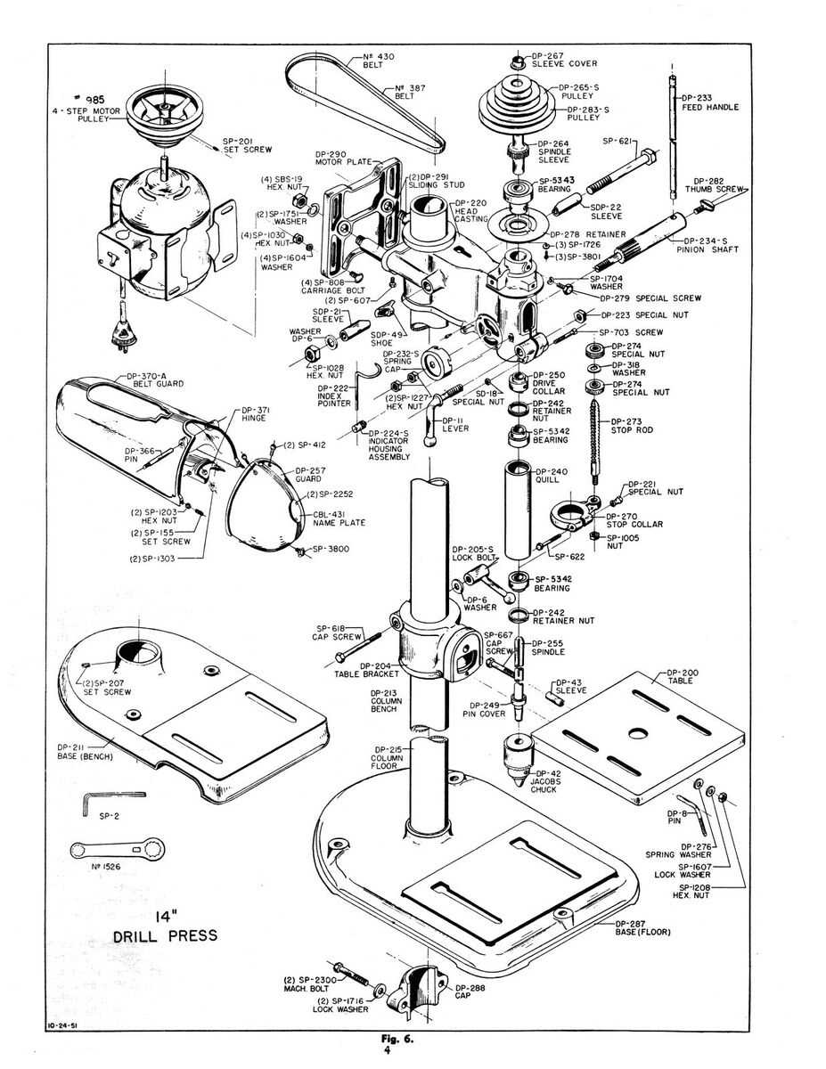
In this guide, we will explore the internal structure of a well-known device. Emphasis will be placed on its major elements, as well as their roles and interactions. Each component plays a specific function, contributing to the overall performance and reliability of the system. By grasping the purpose and position of each piece, users can better maintain the unit and ensure its optimal functionality over time.
The following overview offers insights into the key modules that compose this machine, detailing their arrangement and how they work together. Whether it’s for upkeep, enhancement, or a deeper comprehension of the mechanics, this breakdown aims to provide a thorough understanding of the equipment’s framework. Such knowledge can be invaluable for technicians, engineers, and enthusiasts looking to make the most out of their investment.
Overview of Delta 2300 Series Components
This section provides a detailed examination of the essential elements and their functions within this model line. Each unit plays a critical role in ensuring the overall efficiency and smooth operation of the system. Understanding the purpose and arrangement of each element helps in effective maintenance and troubleshooting.
- Control Unit: Acts as the central hub, managing signals and coordinating the activities of connected modules. It ensures proper communication between various sections.
- Power Module: Supplies energy to the entire assembly, converting input power into a usable form for other units. It is designed for stability and consistent delivery.
- Cooling Mechanism: Comprises fans and heat sinks that maintain optimal temperature levels, preventing overheating and ensuring longevity.
- Input/Output Interface: Allows interaction with external devices, providing connections for data transfer and communication with peripheral equipment.
- Drive Unit: Responsible for precise control and movement, enabling accurate operation through mechanical components. It enhances responsiveness and precision in action.
The arrangement and interplay of these elements contribute significantly to the performance of the system, making it a versatile solution for various applications. This structure facilitates easy access for repairs, replacements, and upgrades, ensuring long-term reliability.
Key Features of the Delta 2300
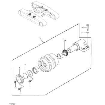
Designed for a wide range of applications, this model combines precision and durability to ensure optimal performance. It is known for its versatility and ability to meet various operational demands, making it a reliable choice for different settings.
- Enhanced Efficiency: The system is equipped with advanced technology that allows it to operate with high energy efficiency, minimizing power consumption while maintaining consistent output.
- Robust Construction: Built with high-quality materials, the unit is designed to withstand challenging conditions, offering long-term durability and reduced maintenance needs.
- User-Friendly Interface: The intuitive control panel and clear indicators make it easy to monitor and adjust settings, providing a seamless user experience.
- Adaptability: This equipment supports a wide range of functions, allowing it to adapt to various requirements, whether in industrial or commercial environments.
- Precision Control: Its ability to deliver accurate results ensures that operations are carried out with minimal errors, making it suitable for tasks that require meticulous attention.
- Safety Features: Integrated safety mechanisms help protect both the device and the user, reducing the risks associated with its operation and providing peace of mind.
With its blend of advanced features and robust design, this model stands out as a versatile solution for those seeking reliability and efficiency.
Understanding Component Placement in the Series
The layout of various elements within this model ensures optimal performance and ease of maintenance. Each element is strategically positioned to balance efficiency and accessibility, allowing users to navigate the internal structure smoothly. By understanding the arrangement, one can more effectively troubleshoot and replace individual pieces when necessary.
Central Mechanisms and Their Accessibility: At the core of the model lie the key mechanical and electrical units. These are positioned centrally to minimize interference and maximize space utilization. Their placement allows for direct access during servicing, making it easier to perform adjustments or inspections.
Peripheral Components and Support Structures: Surrounding the central units, the auxiliary parts play a vital role in supporting the primary functions. These components are distributed around the edges, ensuring that they do not obstruct access to critical areas. This thoughtful distribution contributes to maintaining a streamlined structure, where every part has its designated space.
Attention to detail in the placement ensures that each section serves its purpose without overlapping or creating unnecessary complexity. This arrangement results in a system that is both robust and user-friendly, designed for both efficiency and longevity.
Detailed Breakdown of Internal Parts
This section offers a comprehensive examination of the components found within the unit, highlighting their functions and interconnections. Understanding these elements is crucial for both maintenance and enhancement of overall performance.
Key Components Overview
- Power Supply: Responsible for converting electrical energy into usable power for various functions.
- Control Board: Acts as the central hub for processing commands and coordinating operations.
- Cooling System: Essential for maintaining optimal temperature and preventing overheating.
- Motor Assembly: Facilitates the movement and operation of various mechanisms.
- Sensor Array: Provides real-time data feedback to ensure accurate performance.
Functionality and Interactions
Each component plays a pivotal role in the unit’s functionality, working in harmony to achieve seamless operation. The interplay between these parts is critical; for instance, the control board processes inputs from the sensor array to adjust the motor assembly’s activity accordingly.
- The power supply ensures consistent energy flow, enabling the control board to function effectively.
- In turn, the control board’s signals activate the motor assembly, while the cooling system remains engaged to prevent excessive heat buildup.
Understanding these relationships enhances the ability to troubleshoot issues and implement upgrades, ultimately leading to improved efficiency and longevity.
Common Replacement Parts for Delta 2300
Maintaining and ensuring optimal performance of equipment often requires the replacement of specific components. Recognizing the essential elements that are commonly swapped out can enhance longevity and functionality.
- Seals: Regular replacement of seals helps prevent leaks and maintain pressure.
- Filters: Air and fluid filters are crucial for keeping the system clean and efficient.
- Belts: Worn or frayed belts can lead to operational inefficiencies and should be replaced as needed.
- Bearings: Bearings experience wear over time and may require periodic replacement to ensure smooth operation.
- Gaskets: Gaskets provide necessary sealing between components, and replacing damaged gaskets is essential to avoid leaks.
Understanding these frequently replaced components can aid in proactive maintenance, ensuring that equipment remains in excellent working condition.
Maintenance Tips for Long-lasting Performance
Ensuring the longevity and efficiency of equipment requires regular upkeep and attention to detail. By adopting effective practices, users can enhance functionality and prevent premature wear. Following a systematic maintenance approach is essential for achieving optimal performance and extending the lifespan of machinery.
Regular Inspection and Cleaning
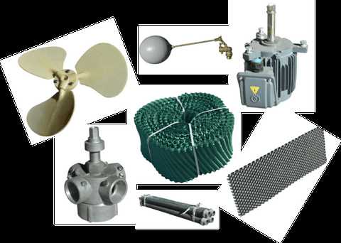
Conducting frequent checks on components is vital to identify any signs of wear or damage early on. Keeping surfaces clean and free from debris will prevent buildup that could hinder performance. Use appropriate cleaning agents and tools to maintain the integrity of all parts, ensuring they function as intended.
Scheduled Lubrication and Adjustments
Proper lubrication is crucial for reducing friction and wear between moving parts. Establish a routine schedule for applying lubricants, ensuring all joints and bearings are adequately serviced. Additionally, periodic adjustments may be necessary to maintain alignment and performance, contributing to the overall efficiency of the equipment.
Visual Guide to the Series Structure
This section offers a comprehensive overview of the components and their relationships within the designated lineup. Understanding the arrangement and functionality of each element can significantly enhance the user experience and facilitate maintenance tasks.
Component Overview
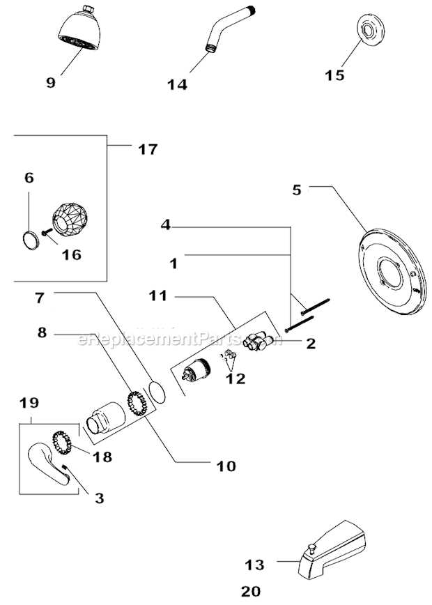
The following table illustrates the key elements, their respective functions, and interconnections. This visual representation serves as a valuable reference for identifying parts and comprehending their roles in the overall system.
| Element Name | Function | Connection Type |
|---|---|---|
| Component A | Primary Functionality | Direct Connection |
| Component B | Supportive Role | Interface |
| Component C | Control Mechanism | Linkage |
| Component D | Power Supply | Input/Output |
Interrelationship of Elements
Understanding how these components interact is crucial for effective operation. Each part contributes to the system’s efficiency, and recognizing their interdependencies can assist users in troubleshooting and optimizing performance.
How to Identify Critical Components
Recognizing essential elements in a system is crucial for effective maintenance and troubleshooting. Understanding the functionality and positioning of these key components enables users to ensure optimal performance and prevent potential failures. This guide will outline methods for pinpointing vital parts within complex machinery.
1. Review Documentation: Begin by consulting the user manual or technical documentation associated with the equipment. This information typically includes diagrams and descriptions that highlight significant components and their roles within the system.
2. Utilize Visual Aids: Employ visual aids such as schematics or annotated images to identify critical components. These resources can provide clarity on how different parts interact and contribute to overall functionality.
3. Conduct a Physical Inspection: Perform a thorough examination of the machinery. Look for labels or markings on components that can indicate their importance. Additionally, pay attention to any signs of wear or damage that may suggest a part is essential for operation.
4. Consult Technical Support: If uncertainty persists, reach out to technical support or experts familiar with the equipment. Their insights can assist in identifying critical components and offer guidance on maintenance practices.
5. Monitor Performance: Keep track of the system’s performance over time. Any irregularities may signal issues with essential parts. Regular monitoring can help in timely identification and replacement of these components before they lead to significant problems.
By following these strategies, users can effectively identify and manage the crucial elements of their equipment, ensuring reliable and efficient operation.
Step-by-Step Assembly Instructions
This section provides a comprehensive guide to assembling the components efficiently. By following the outlined steps, you will ensure that each part is correctly positioned and secured, leading to optimal performance.
- Begin by gathering all necessary components and tools. Ensure that you have everything within reach to streamline the process.
- Refer to the assembly layout to identify the primary sections. This will help you visualize the final structure and understand the placement of each item.
- Start with the base component. Secure it on a stable surface to prevent any movement during assembly.
- Next, attach the vertical sections. Align them carefully with the base, ensuring that all connection points are properly matched.
- Once the vertical sections are in place, proceed to install the horizontal components. Check that each piece fits snugly into its designated slot.
- Secure all joints and connections using the appropriate fasteners. Make sure each fastener is tightened to avoid any loose fittings.
- After completing the structural assembly, conduct a thorough inspection. Verify that all components are aligned and secure.
- Finally, perform a functionality test to confirm that everything operates as intended. Make any necessary adjustments if issues arise.
Following these steps will lead to a successful assembly, ensuring the durability and efficiency of the assembled system.
Troubleshooting Common Issues in the 2300
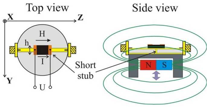
When dealing with equipment of this type, users may encounter several frequent challenges that can hinder optimal performance. Understanding these issues and their potential solutions can significantly improve the efficiency and lifespan of the device.
Below are some common problems and their corresponding troubleshooting steps:
- Device Not Starting
- Check the power source to ensure it is functioning correctly.
- Inspect all connections for any signs of damage or loose fittings.
- Examine the internal fuse; if blown, replace it with a suitable alternative.
- Overheating
- Verify that the ventilation openings are clear of obstructions.
- Ensure that the cooling system is operational and free of dust buildup.
- Reduce the load on the device to prevent excessive strain.
- Inconsistent Output
- Inspect all output connections for wear or damage.
- Calibrate the settings according to the manufacturer’s specifications.
- Replace any faulty components that may be affecting performance.
- Unusual Noises
- Identify the source of the noise and check for loose parts.
- Lubricate moving components to reduce friction and wear.
- If the noise persists, consult a professional for further evaluation.
By following these steps, users can effectively diagnose and resolve common issues, ensuring that their equipment remains in peak operating condition.
Comparing Different Models Within the Series
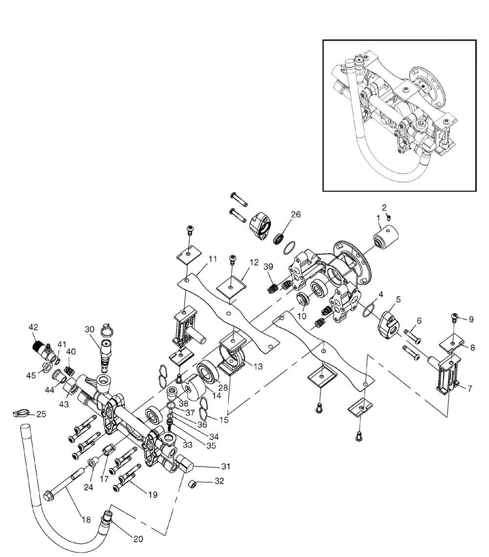
This section explores the nuances among various models in a specific lineup, highlighting the distinctions that cater to different user needs and applications. By examining features, specifications, and performance, potential buyers can make informed decisions based on their requirements.
Key Features Overview
Each model presents unique attributes that enhance usability and efficiency. Some variants are designed for heavy-duty tasks, while others offer advanced technology for precision applications. Understanding these features allows users to select the option that best fits their operational demands.
Performance and Usability
The performance metrics can vary significantly across models, impacting their suitability for various tasks. Assessing usability is crucial; certain models may prioritize ease of use, while others focus on robust functionality. Users should consider their primary objectives when choosing the most appropriate variant.
Exploring Electrical Connections and Layout
This section delves into the intricate web of electrical linkages and configurations found in the specified apparatus. Understanding how these connections interact is crucial for optimal performance and maintenance. The layout significantly influences the efficiency and reliability of the system, making it essential for users and technicians to familiarize themselves with the design.
The following table illustrates the primary electrical components and their interconnections, providing a clear overview of the configuration:
| Component | Function | Connection Type |
|---|---|---|
| Control Board | Regulates operations | Wired |
| Power Supply | Provides energy | Wired |
| Motor | Drives mechanical parts | Wired |
| Sensor | Monitors conditions | Wireless |
| Interface Panel | User interaction | Wired |
Familiarity with these components and their arrangement is essential for troubleshooting and enhancing the functionality of the equipment. Each connection serves a specific purpose, contributing to the overall operation and efficiency of the system.
Upgrades and Modifications for Better Efficiency
Enhancing performance and maximizing productivity often require careful consideration of existing configurations and potential enhancements. By implementing strategic upgrades and modifications, users can significantly improve operational effectiveness while also extending the lifespan of their equipment. This section explores various approaches to achieve optimal efficiency.
Key Areas for Improvement
- Power Management: Adjusting settings and optimizing power consumption can lead to substantial energy savings.
- Component Upgrades: Replacing outdated elements with advanced alternatives can enhance performance and reliability.
- Cooling Solutions: Implementing better cooling systems ensures consistent operation and prevents overheating.
Recommended Modifications
- Install high-efficiency motors to reduce energy consumption.
- Incorporate programmable controllers to automate processes and improve precision.
- Enhance filtration systems to maintain optimal performance and protect internal components.
By focusing on these upgrades and modifications, users can create a more efficient environment that meets both current demands and future challenges.