Ford Jubilee Parts Diagram
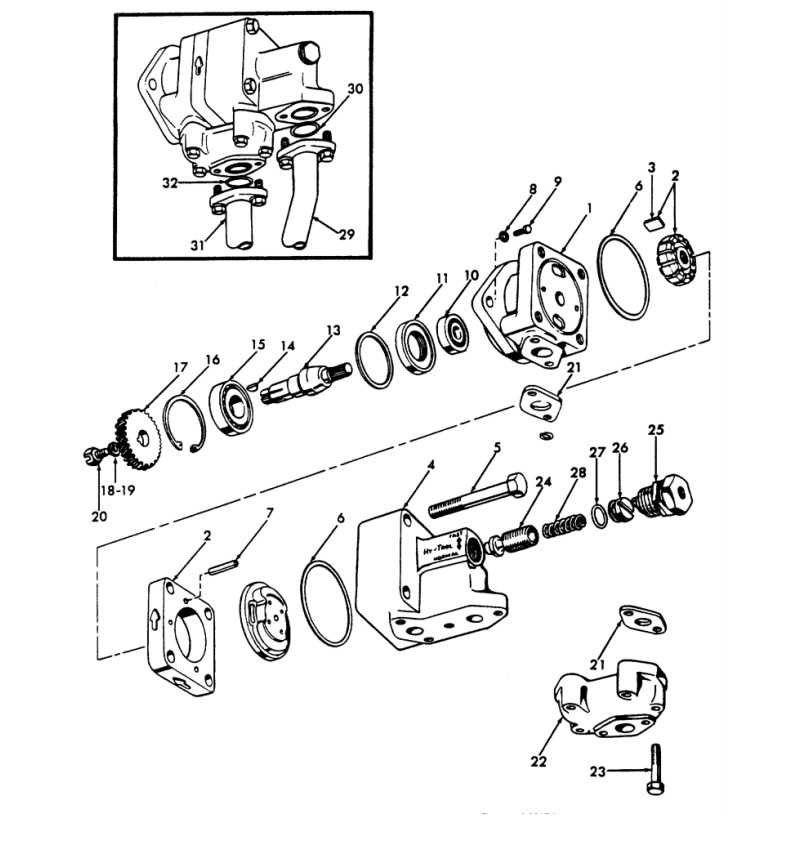
When working with classic automotive models, it is crucial to have a detailed understanding of each individual element that makes up the machine. These components play specific roles in the overall functionality and performance of the vehicle. Whether you are restoring a vintage model or simply maintaining one, knowing how each part interacts within the system is key to ensuring longevity and reliability.
Technical reference materials are invaluable tools for anyone involved in the restoration or maintenance of an older automobile. They provide clear insights into the design and arrangement of the various mechanical and electrical systems. With proper documentation, users can easily identify each part’s function and its relationship to others, allowing for precise repairs and replacements when necessary.
The visual representation of these systems often simplifies the process of assembly and disassembly. By breaking down the complex structure into understandable sections, it allows mechanics and enthusiasts alike to gain a deeper appreciation of the engineering behind these iconic machines. Understanding the layout of essential components can make all the difference in achieving an optimal result.
Ford Jubilee Parts Diagram Overview
This section provides a detailed exploration of the visual representation of the various components and their layout for the vintage model. Understanding the arrangement of these elements helps enthusiasts and mechanics to efficiently locate parts, recognize configurations, and manage maintenance tasks effectively. A comprehensive reference of the system’s structure can greatly enhance both assembly and repair processes.
Key Component Arrangement
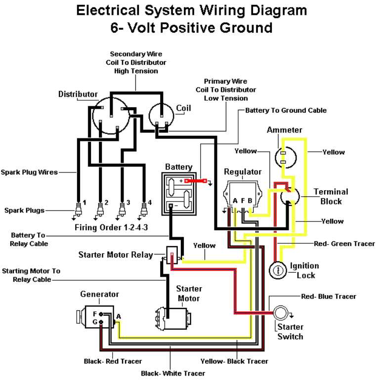
The illustration showcases the organization of essential elements within the system, ensuring that each part is easily identifiable. This aids in the efficient reassembly of the unit or replacement of worn components. Whether dealing with engine, transmission, or electrical systems, having a clear representation of how each piece interconnects is crucial for smooth operations.
Understanding System Layout
A complete overview of the internal structure offers a better grasp of the functional connections between mechanical parts. It also assists in the identification of potential wear areas, allowing users to address any issues before they become major concerns.
| Component | Description |
|---|---|
| Engine | Central unit that powers the system, incorporating various subcomponents for fuel, cooling, and exhaust management. |
| Transmission | Transmits power from the engine to the wheels, involving gears and linkages for speed adjustments. |
| Suspension | System that absorbs shocks and maintains stability, connecting the body to the wheels and allowing for controlled movement. |
| Electrical System | Includes all wiring, switches, and components for lighting, ignition, and other electrical functionalities. |
Engine Components in Ford Jubilee
The power unit of a vintage tractor consists of several essential components working together to ensure optimal performance and reliability. These elements are designed to convert fuel into mechanical energy, allowing the vehicle to perform various tasks efficiently. Understanding each part’s role helps in maintaining and repairing the engine when necessary.
Among the core elements, the following are crucial for the engine’s operation:
- Crankshaft: The central part that transforms linear motion into rotational movement.
- Pistons: Moving components within the cylinders that drive the mechanical energy conversion process.
- Camshaft: Controls the opening and closing of the engine’s intake and exhaust valves.
- Valves: Essential for regulating air and fuel intake, as well as exhaust expulsion.
- Timing Chain: Ensures synchronization between the crankshaft and camshaft.
Regular inspection of these components is essential for smooth engine operation, reducing the likelihood of wear and tear over time. Each part contributes to the vehicle’s overall power delivery and operational efficiency.
Transmission System Breakdown
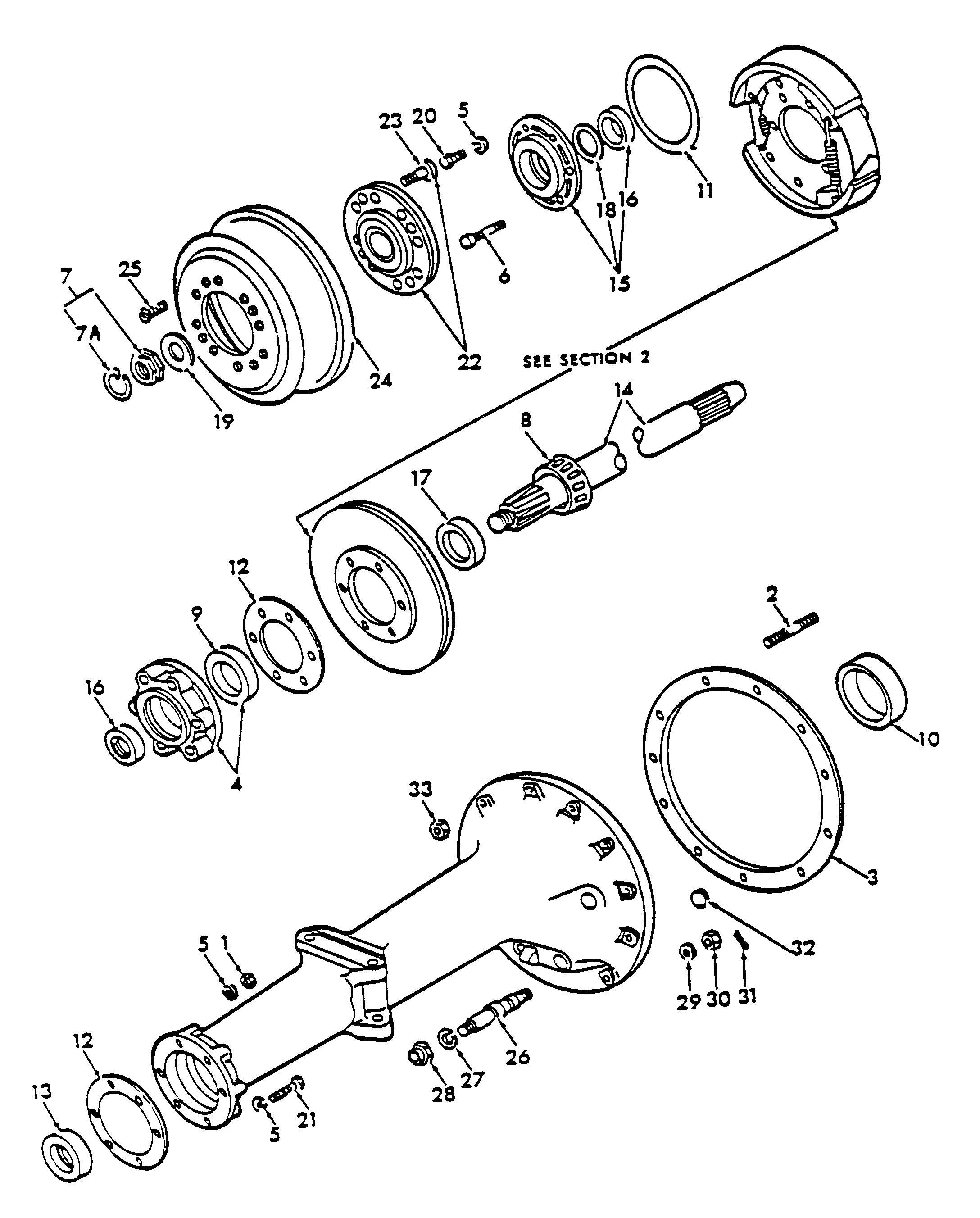
The transmission system plays a crucial role in ensuring smooth power delivery from the engine to the wheels. A detailed breakdown of the components within this system is essential for understanding its function and identifying potential issues that may arise during operation.
Below is a breakdown of the key elements that make up the transmission system:
- Clutch – Responsible for engaging and disengaging the engine from the drivetrain, allowing smooth gear changes.
- Gearbox – Contains the gears necessary to adjust the torque and speed sent to the wheels. It can be either manual or automatic.
- Driveshaft – Transfers the rotational force from the gearbox to the wheels, enabling movement.
- Differential – Distributes power to the wheels, allowing them to rotate at different speeds, especially during turns.
- Synchronizers – Ensure that the gears engage smoothly, preventing grinding or skipping.
Each of these parts plays a specific role in maintaining the overall functionality of the drivetrain. Any malfunction in one of these components can lead to issues such as slipping, difficulty in shifting, or loss of power transfer, requiring immediate attention to restore performance.
Fuel System and Its Parts
The fuel delivery mechanism is essential for the proper operation of any internal combustion engine. It ensures that the engine receives the correct amount of fuel at the right time for optimal performance. This system is composed of several key components that work together to store, regulate, and inject fuel into the engine for combustion.
Fuel Tank is where the fuel is stored before being delivered to the engine. It is equipped with a fuel pump that draws the fuel through pipes to other system components. The tank is usually made of durable materials to withstand impacts and prevent leaks.
Fuel Pump plays a critical role in transferring fuel from the tank to the engine. This component is typically electrically powered and ensures that fuel is delivered at the required pressure for efficient combustion.
Fuel Filter serves to clean the fuel before it enters the engine, removing dirt, rust, and other contaminants. By maintaining fuel purity, this part helps prevent clogging and damage to more sensitive engine components.
Fuel Injector is responsible for spraying the correct amount of fuel into the engine’s combustion chamber. It works in harmony with the engine’s control system to ensure precise fuel delivery, contributing to optimal fuel efficiency and performance.
Fuel Pressure Regulator maintains consistent pressure in the fuel system. It adjusts the flow of fuel based on engine requirements, ensuring that the correct amount of fuel is always available for efficient combustion.
Fuel Lines are the conduits that transport fuel from the tank to the engine. These lines must be resistant to heat, pressure, and corrosion to avoid leaks and ensure a reliable fuel supply.
All these components must work seamlessly together to provide the engine with the right amount of fuel under various conditions. Maintaining these parts ensures smooth engine operation and long-term reliability.
Electrical Wiring Diagram for Jubilee
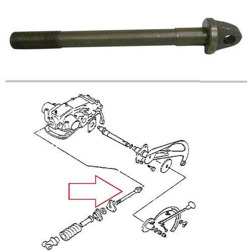
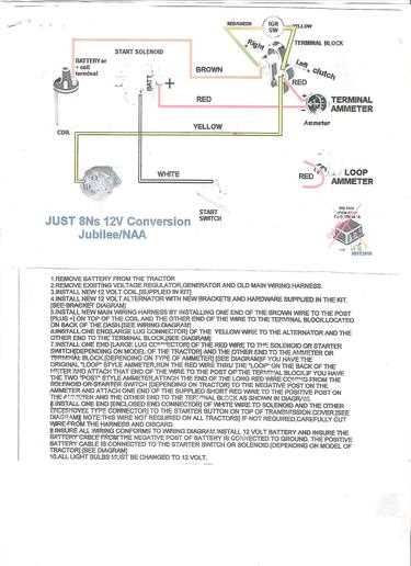
This section covers the essential details related to the electrical connections of the classic vehicle, focusing on the key components and their wiring paths. The layout and interconnections ensure that each part functions harmoniously, providing power and control to various systems, such as the engine, lighting, and sensors. Proper understanding of this wiring setup is crucial for maintenance and troubleshooting, helping to ensure optimal performance and safety.
Key Electrical Components
In any motorized vehicle, the electrical system is composed of several critical components. These include the power source, switches, relays, and wiring harnesses. Each element must be correctly wired to ensure that the current flows efficiently, triggering the necessary responses from various systems. Below is a detailed look at the major components and their interconnections.
Connection Overview
The electrical connections between the power source, switches, and other components must follow a specific pattern for proper functionality. The layout of wires and their routing through the system ensures a stable and uninterrupted supply of electricity, preventing malfunction and enhancing the overall driving experience.
| Component | Purpose | Connection |
|---|---|---|
| Power Supply | Provides electrical energy to all components | Connected to battery and alternator |
| Ignition Switch | Controls the start-up process | Connected to the starter motor and fuse panel |
| Relays | Regulate the flow of current to various components | Connected to ignition switch and various electrical parts |
| Fuse Box | Protects electrical circuits from overloads | Linked to power supply and relays |
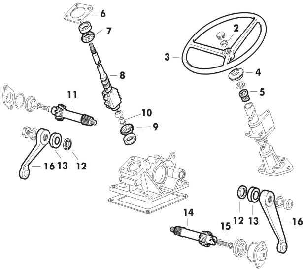
Suspension and Steering Mechanisms
The efficiency of a vehicle’s ride quality and handling characteristics is significantly influenced by its suspension and steering systems. These components work together to provide stability, comfort, and control while navigating various terrains. Understanding their design and functionality is essential for optimizing performance and ensuring safety.
Suspension systems are responsible for absorbing shocks from uneven surfaces, maintaining tire contact with the ground, and supporting the vehicle’s weight. This complex arrangement comprises various elements such as springs, dampers, and linkages, which collectively enhance ride comfort and reduce body roll during turns. Proper maintenance of these components is crucial for preserving handling precision and preventing premature wear.
On the other hand, the steering mechanism allows the driver to guide the vehicle effectively. It translates the driver’s input into precise wheel movement, which is vital for maneuverability. Different types of steering systems, such as rack-and-pinion and recirculating ball, offer distinct advantages regarding responsiveness and ease of use. Regular inspection and adjustment of the steering components can help maintain optimal performance and safety.
In summary, the interplay between the suspension and steering mechanisms plays a vital role in determining a vehicle’s overall driving experience. Understanding the intricacies of these systems can lead to better maintenance practices and informed decisions regarding upgrades or repairs.
Brake System Components Explained
The braking system of any vehicle is a critical part of its overall functionality. It is designed to provide safety and control by reducing speed or bringing the vehicle to a complete stop. Understanding the various elements involved can help in appreciating how they work together to ensure smooth and reliable operation when needed the most.
The brake pads are one of the primary components that create friction to slow down or stop the vehicle. These pads press against a rotating surface, converting the vehicle’s kinetic energy into heat. Similarly, the rotors (or discs) provide the surface on which the pads act. The condition of both the pads and rotors is essential for effective braking performance, and wear and tear can significantly impact their efficiency.
The calipers are responsible for pressing the brake pads against the rotors. They house the pistons that push the pads, and the hydraulic pressure generated by the brake fluid controls their movement. The master cylinder is the central hub of the braking system, which controls the flow of brake fluid to the calipers, enabling the system to respond to the driver’s input on the brake pedal.
Additionally, the brake lines serve as the channels through which the brake fluid travels, connecting the master cylinder to the calipers. This fluid is key in transferring force from the pedal to the braking components. A well-maintained fluid level is crucial for optimal function, as low fluid levels can lead to inefficient braking or even system failure.
All these parts, along with the brake booster that assists with pedal force and the ABS system (anti-lock braking system) that prevents wheel lockup, work together to provide the necessary stopping power and control. Regular maintenance of these components is necessary to ensure safety and efficiency during operation.
Cooling System and Its Parts
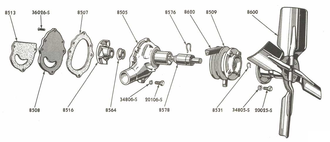
The cooling system plays a crucial role in maintaining optimal operating temperatures for an engine. It prevents the engine from overheating, ensuring efficient performance and longevity. This system relies on various components that work in harmony to regulate temperature, circulate coolant, and dissipate heat effectively. Understanding the function of each element is key to ensuring smooth engine operation and preventing potential damage due to excessive heat buildup.
Main Components of the Cooling Mechanism
The primary components of the cooling setup include the radiator, thermostat, water pump, and cooling fans. The radiator is the core element responsible for transferring heat away from the coolant. The water pump circulates the coolant throughout the system, while the thermostat regulates the coolant’s flow to maintain the desired engine temperature. Additionally, cooling fans help to enhance air circulation around the radiator, ensuring efficient heat dissipation.
Importance of Regular Maintenance
Maintaining each of these components is essential for the system’s effectiveness. Regular checks, such as inspecting coolant levels, verifying the integrity of hoses, and ensuring that fans and pumps function properly, are necessary to avoid system failure. Neglecting these parts may lead to overheating, which can severely damage the engine and other vital components.
Exhaust System Details
The exhaust system is a critical component designed to manage the flow of gases produced during the combustion process in an engine. Proper function of this system ensures efficient performance, lower emissions, and improved overall engine health. In this section, we’ll break down the individual elements of this system and their roles in maintaining optimal operation.
Main Components
- Exhaust Manifold: Collects gases from the engine cylinders and directs them into the exhaust system.
- Exhaust Pipe: Transports the exhaust gases from the manifold to the rest of the system.
- Catalytic Converter: Reduces harmful emissions by converting toxic gases into less harmful ones before they exit the vehicle.
- Muffler: Reduces noise produced by the exhaust gases as they exit the vehicle.
- Tailpipe: The final exit point for the exhaust gases, directing them away from the vehicle.
Maintenance Considerations
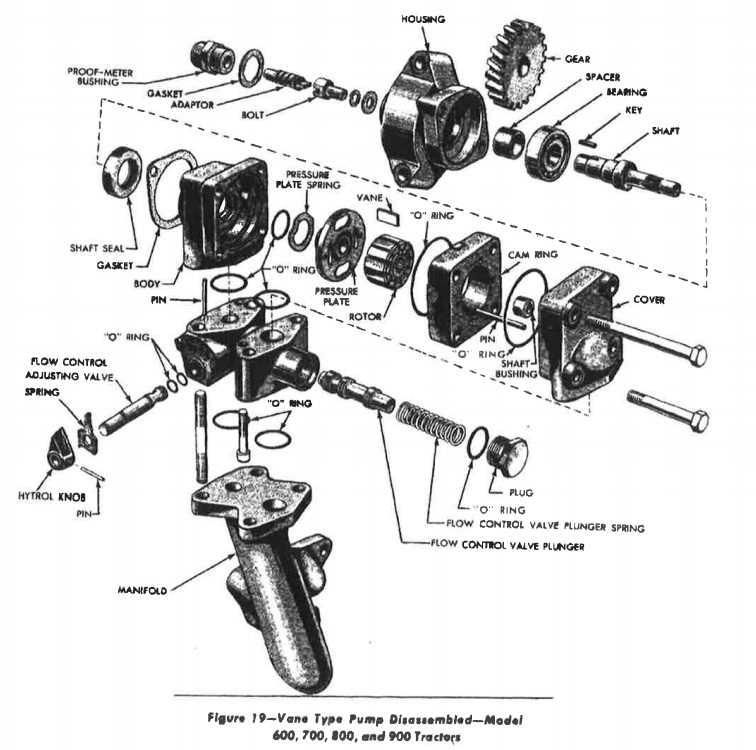
- Regular checks for leaks, cracks, or corrosion in the system are essential for maintaining performance.
- Cleaning and replacing the catalytic converter can ensure that harmful emissions are minimized.
- Monitoring the muffler and exhaust pipe condition helps to maintain proper noise levels and avoid system failure.
Hydraulic System and Its Function
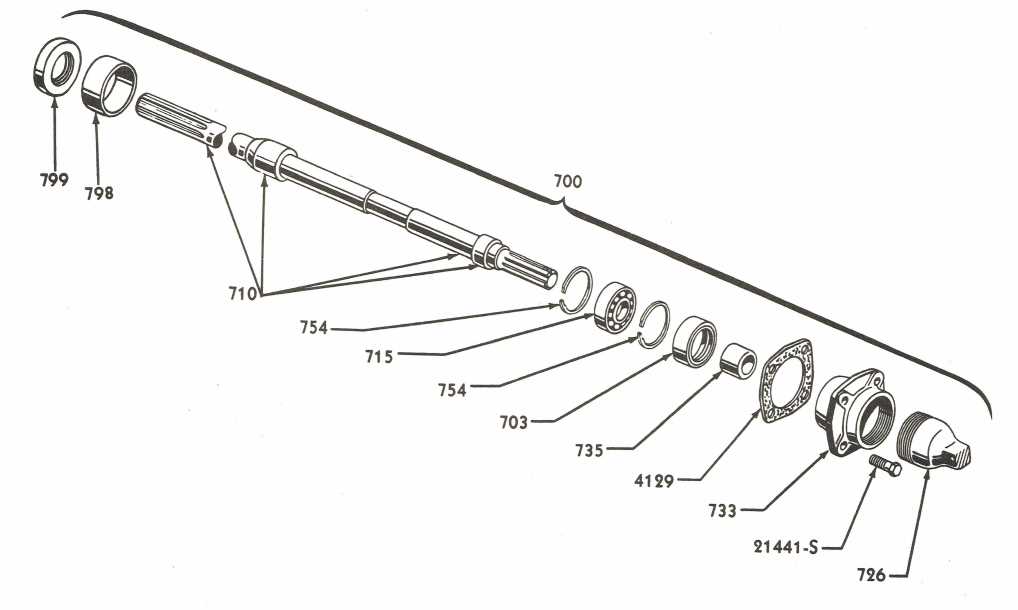
The hydraulic system plays a crucial role in providing the necessary force to power various mechanical components in machinery. It uses fluid pressure to transmit energy, enabling different parts of the machine to move and operate efficiently. By converting mechanical energy into hydraulic power, this system supports a range of functions, from lifting to precise control of movement.
Principle of Operation
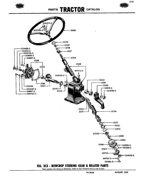
At the core of the hydraulic system lies the principle that pressure applied to a confined fluid is transmitted equally in all directions. This allows for the movement of large components with minimal effort. The system consists of several components, including a pump, valves, and cylinders, each playing an essential role in controlling fluid flow and directing it to the appropriate areas.
Key Functions and Applications
Hydraulic systems are used in a variety of applications, from agricultural machinery to industrial equipment. The system enables operators to easily lift heavy loads, adjust positioning, and control force with great precision. Efficiency and reliability make hydraulic systems indispensable for tasks requiring power and flexibility, often under challenging conditions.
Chassis and Frame Assembly Diagram
The foundation of any vehicle is its structural frame, which provides support and stability to all other components. This essential part serves as the skeleton, connecting the various mechanical systems, suspension elements, and body panels. Understanding how these elements fit together is crucial for ensuring the integrity and functionality of the entire vehicle.
The assembly of the chassis and frame is a meticulous process, where each section is designed to bear specific loads and stresses. Key parts of this structure include cross members, side rails, and supports that are welded or bolted together to form a solid base. Proper alignment and secure attachment are vital to maintain the overall performance and safety of the vehicle.
The connection points between the frame and suspension components must be precisely engineered to absorb impacts and vibrations, ensuring smooth handling and ride comfort. In addition, the chassis houses various mounting brackets for engines, transmission systems, and other vital machinery, each requiring a durable and well-calibrated fit.
Tire and Wheel Specs
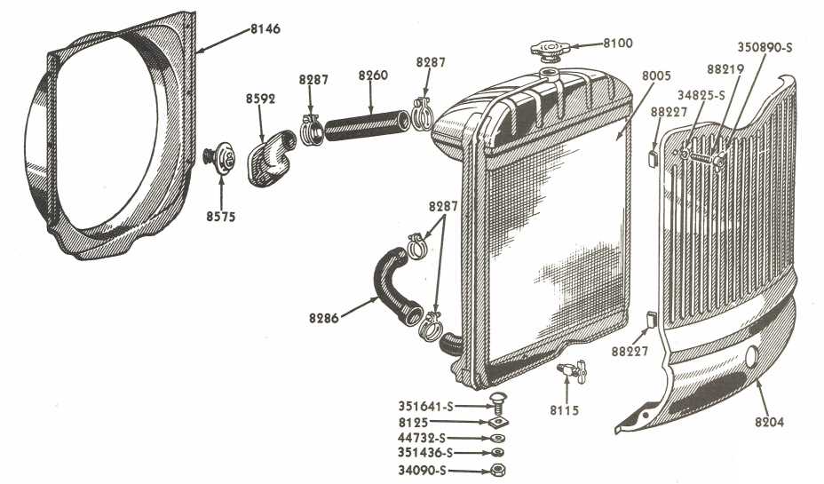
The correct specifications for tires and wheels play a vital role in ensuring the smooth operation and performance of agricultural machinery. It is important to understand the required dimensions, load capacity, and compatibility of these components for proper functionality.
- Wheel Size: Typically, these machines are equipped with wheels ranging from 16 to 24 inches in diameter. The wheel’s width generally varies between 5 to 8 inches depending on the specific requirements.
- Tire Dimensions: The recommended tire size is usually marked as 6.00-16, with variations available depending on the type of terrain the equipment will be used on.
- Load Capacity: Tires are selected based on their load-bearing capacity. Commonly, the capacity ranges from 1,000 to 1,500 pounds per tire for standard use cases.
- Type of Tires: Options include bias-ply and radial tires, with bias-ply being more common for traditional machines due to their durability and cost-effectiveness.
Proper selection and maintenance of these components are crucial for safety, stability, and efficiency in various field operations. Always ensure that the specifications match the needs of the machine to avoid any performance issues.
Maintenance and Repair Tips
Proper upkeep and timely repairs are essential to prolong the life of your vehicle and ensure it performs at its best. Regular inspections and attention to key components help avoid costly issues and enhance overall reliability. This section provides valuable guidance on maintaining and fixing common problems, keeping your machine running smoothly for years to come.
General Maintenance Guidelines
- Check Fluids Regularly: Always monitor engine oil, transmission fluid, brake fluid, and coolant levels. Low fluid levels can lead to significant engine and transmission damage.
- Inspect the Tires: Ensure tires are properly inflated and check for wear. Regular tire rotations and balancing will improve handling and extend tire life.
- Clean and Replace Filters: Air and fuel filters play a critical role in engine performance. Clean or replace them as needed to maintain optimal airflow and fuel efficiency.
- Examine Belts and Hoses: Check for signs of wear, cracking, or leakage. Worn belts and hoses can lead to engine overheating or failure.
Repair Tips for Common Issues
- Engine Stalling: If the engine stalls frequently, check for issues with the fuel system or ignition components. Inspect the fuel pump, spark plugs, and fuel injectors.
- Brake Problems: If the brakes feel soft or unresponsive, examine the brake pads and fluid levels. Worn-out pads or air in the brake lines are common culprits.
- Suspension Issues: A bumpy ride may indicate suspension problems. Inspect shock absorbers, struts, and bushings to ensure a smooth and comfortable driving experience.
- Electrical System Malfunctions: A dead battery, faulty alternator, or damaged wiring can lead to electrical issues. Check the battery terminals and connections for corrosion or loose connections.