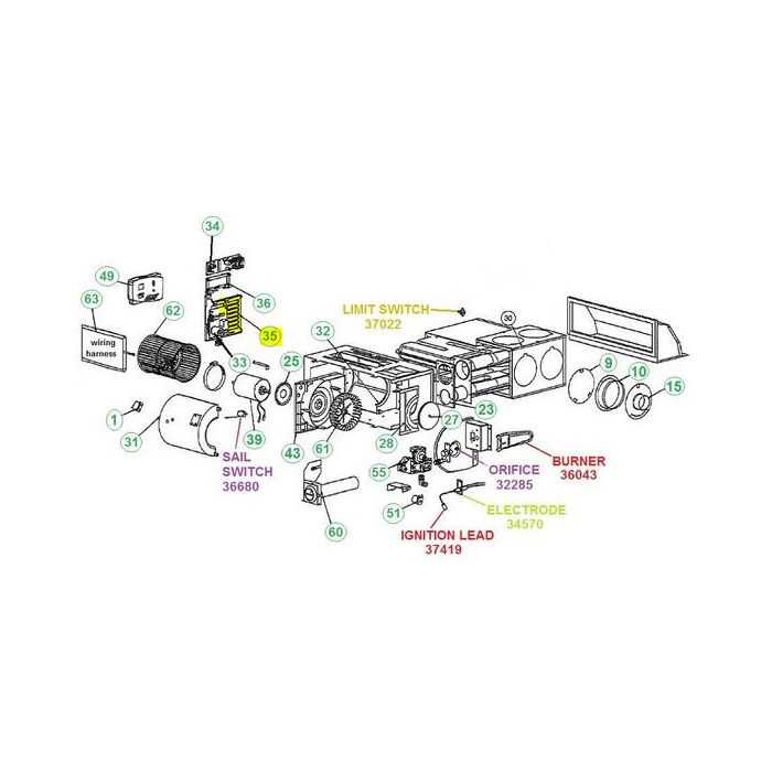
Atwood 8500 Furnace Components Overview
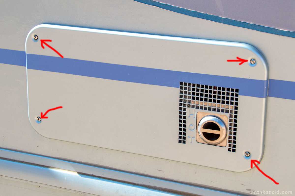
Modern heating units are designed to provide efficient warmth and comfort, especially during colder months. These devices consist of various essential elements working together to ensure proper functionality. Each part plays a vital role in maintaining the desired indoor climate by regulating heat distribution and energy efficiency.
In this section, we will explore the core elements typically found in these systems, highlighting their importance and how they contribute to the overall operation. A clear understanding of these components can assist in diagnosing potential issues and ensuring the longevity of the equipment.
By focusing on the main elements involved, this guide will help you become more familiar with the structure and mechanics of heating devices. Whether you are maintaining or repairing your system, this knowledge is crucial for ensuring optimal performance.
Overview of Atwood 8500 Furnace Components
This section provides a comprehensive look into the key elements that ensure the efficient operation of a heating system. Understanding the individual components and their functions can help with maintenance, troubleshooting, and potential repairs.
- Control Board: The central hub that manages and coordinates the entire heating process, ensuring each part works harmoniously.
- Blower Motor: Responsible for circulating warm air throughout the space by pushing it through the vents.
- Ignition System: A crucial mechanism that ignites the fuel source, initiating the heating process.
- Gas Valve: Regulates the flow of gas into the system, maintaining safe and efficient fuel delivery.
- Thermostat Connection: Interfaces with the temperature control device, allowing adjustments based on the desired comfort level.
- Limit Switch: A safety feature designed to prevent overheating by shutting down the system if temperatures exceed safe limits.
Each of these components plays an essential role in ensuring the system runs smoothly and efficiently, contributing to overall performance and longevity.
Key Elements of the Combustion System
The combustion system in heating equipment relies on several essential components that work together to ensure efficient fuel burning and heat generation. Understanding these elements helps maintain optimal performance and safety during operation.
Fuel Supply and Ignition
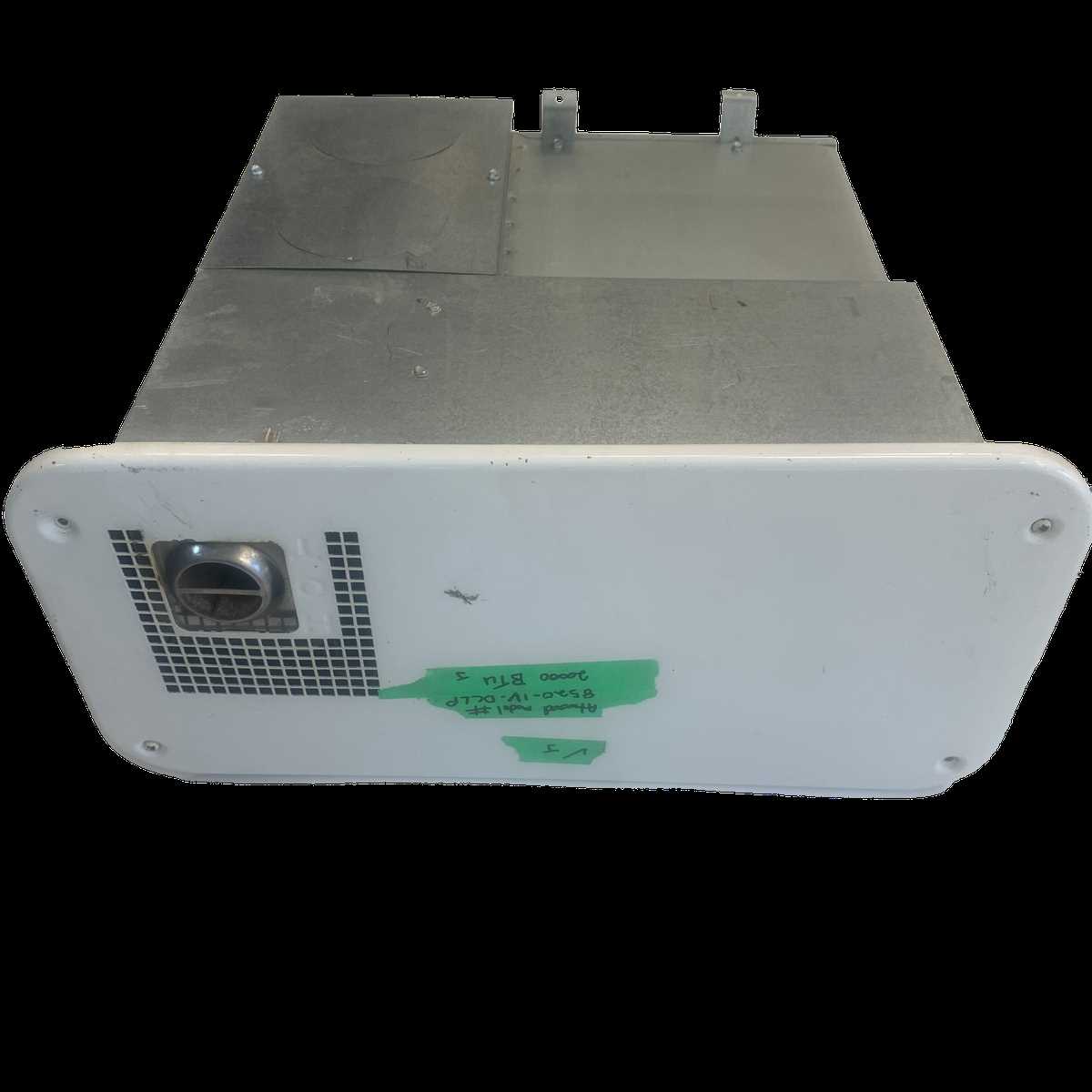
At the heart of the combustion process is the fuel supply, which delivers the necessary energy for heat production. An ignition system initiates the combustion by igniting the fuel, creating the flame that powers the heating mechanism.
- Fuel valve: Regulates the flow of fuel to the burner.
- Igniter: Sparks or heats to start the combustion process.
- Burner assembly: Distributes fuel in a controlled manner for consistent ignition.
Airflow and Exhaust
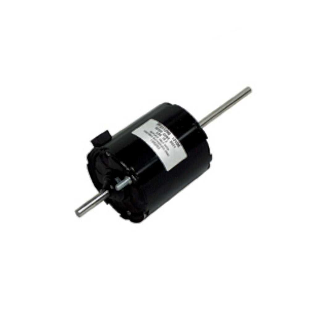
A proper airflow system is crucial for supporting combustion by delivering oxygen and removing harmful gases. The balance between incoming air and outgoing exhaust ensures safety and efficiency.
- Bl
Exploring the Control Board Functions
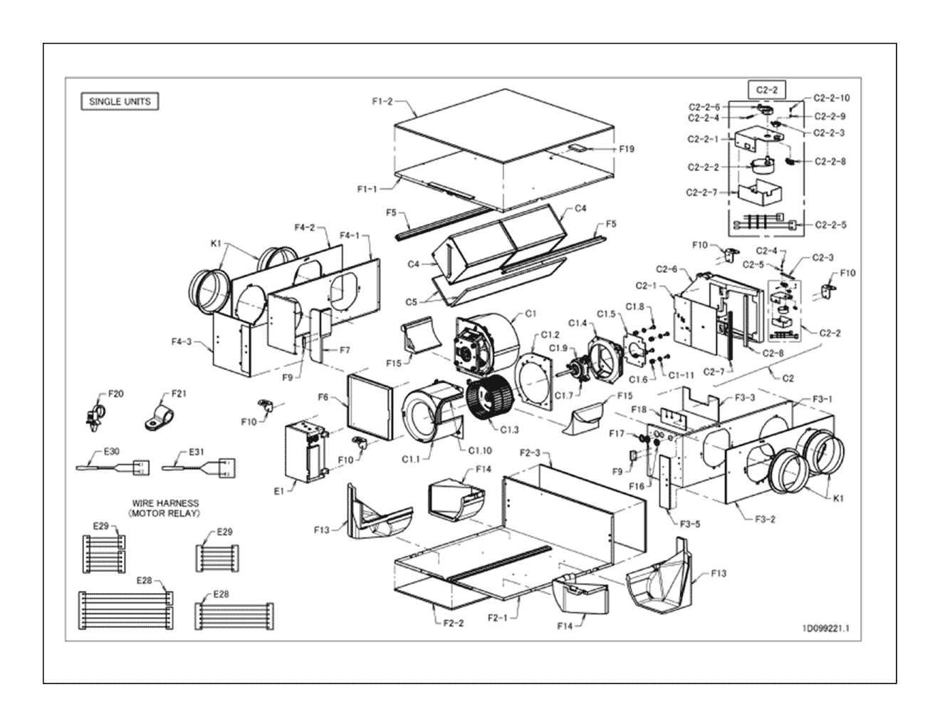
The control board plays a crucial role in managing the overall operation of the heating system. It ensures that various components work in harmony by receiving and processing signals from different sensors and switches. Understanding its functions can help in diagnosing and maintaining the system more efficiently.
Key Responsibilities of the Control Board
- Coordinating the ignition sequence to ensure safe startup.
- Monitoring temperature sensors to maintain optimal heat levels.
- Managing fan speeds to regulate air circulation.
- Controlling the operation of safety switches to prevent malfunctions.
Troubleshooting Common Issues
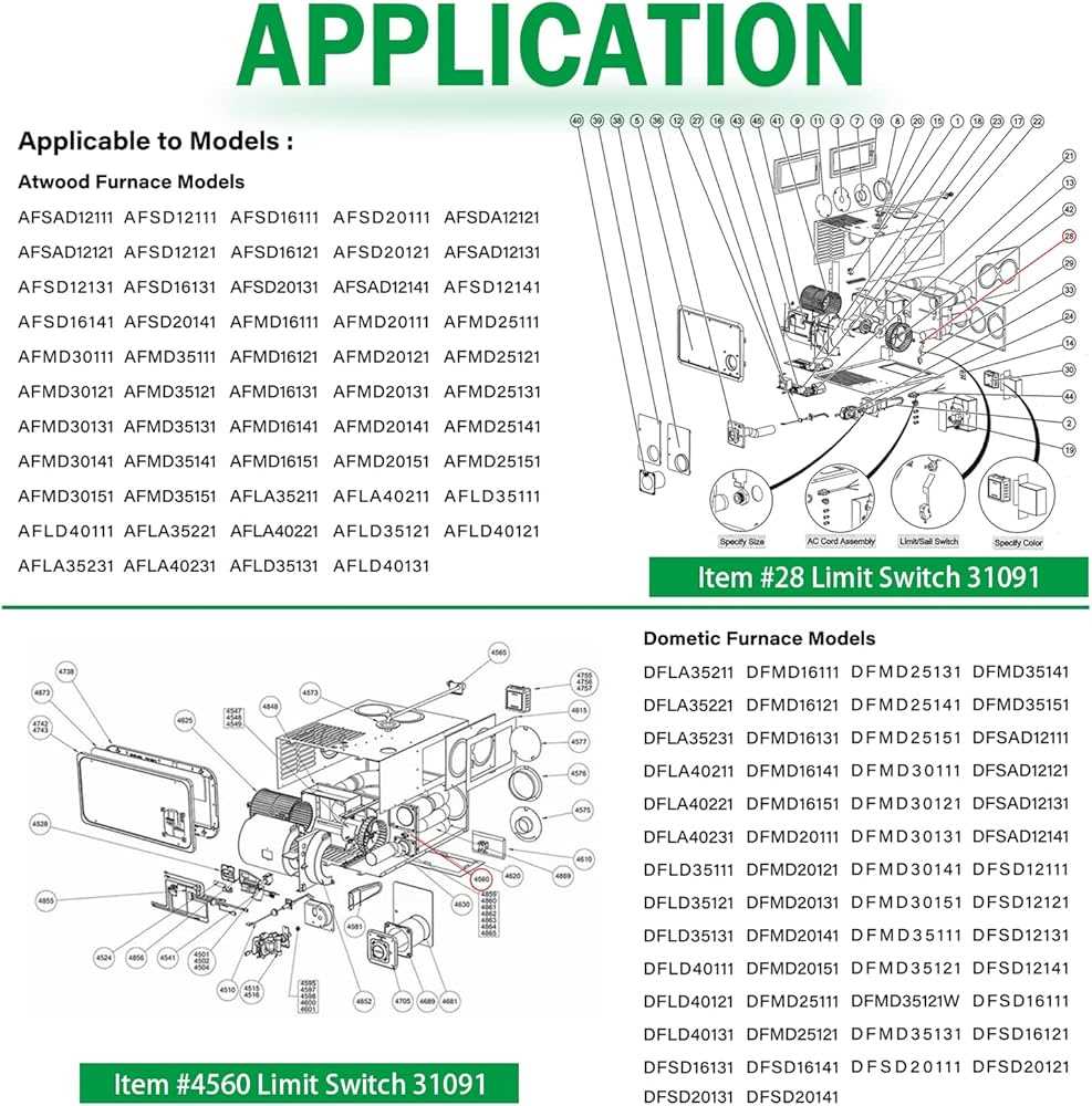
- Failure to start could indicate a problem with the ignition control.
- Inconsistent heating might be related to faulty temperature sensors.
- Unexpected shutdowns may be caused by tripped safety switches.
By understanding these key functions, it’s easier to diagnose issues and ensure smooth operation of the heating system.
Understanding the Gas Valve Operation
The gas valve plays a crucial role in the overall functionality of heating systems. It controls the flow of gas, ensuring the right amount is delivered at the correct time for safe and efficient operation. Understanding how this component works can help in maintaining the system’s reliability and safety.
Main Function of the Gas Valve
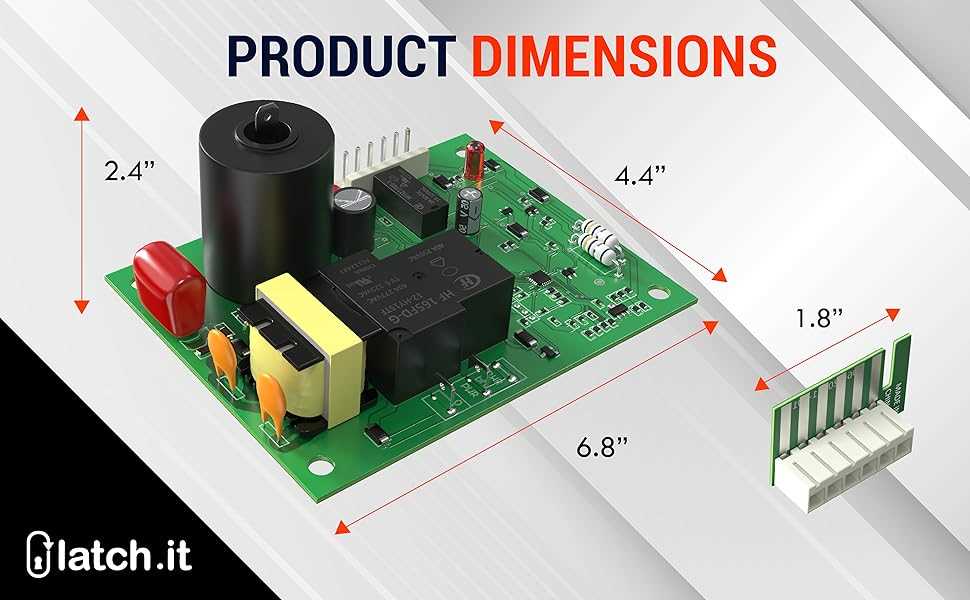
The primary role of the valve is to regulate the flow of gas into the system. It operates in response to the thermostat’s commands, opening and closing to manage gas intake. This controlled process ensures that the correct amount of fuel is provided to produce heat without waste or danger.
Stages of Gas Valve Operation
The operation of the gas valve involves multiple stages, from initial activation to shutdown. The thermostat signals the valve when there is a need for heat, opening the pathway for gas to flow. After the required amount of gas enters, the valve closes to prevent any excess. Understanding these stages can aid in diagnosing potential issues.
Stage Description Activation The thermostat sends a signal, prompting the valve to open and allow gas to enter the system. Flow Control The valve regulates the amount of gas flowing into the Detailed Breakdown of the Blower Assembly
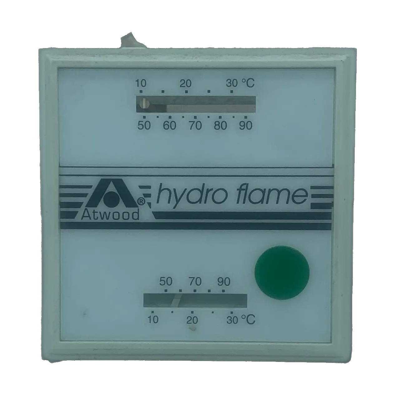
The blower assembly is a key component responsible for ensuring proper airflow through the heating system. Its correct operation is essential for maintaining optimal temperature control and energy efficiency. This section will provide a thorough explanation of the individual elements that make up the blower, highlighting their roles and interactions within the system.
Main Components of the Blower
- Motor: Powers the entire unit, driving the fan blades to circulate air.
- Fan Blades: These rotate to push air through the system, ensuring a steady flow of air to the heat exchanger and other sections.
- Housing: Encases the motor and blades, directing the airflow through the system.
Additional Elements
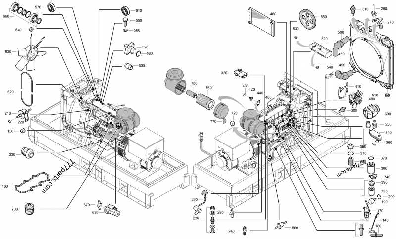
- Mounting Brackets: Secure the blower assembly in place, minimizing vibration during operation.
- Control Board: Manages the blower’s speed and operation based on temperature settings and sensor input.
- Wiring Connections: Provide the necessary electrical links between the blower and the control board, ensuring coordinated operation.
Each part of the blower assembly plays a critical role in maintaining effective air distribution, contributing to the overall performance and efficiency of the heating system.
Electrical Connections and Their Importance
The correct configuration of electrical connections plays a crucial role in ensuring the smooth operation of heating systems. Proper wiring guarantees that components communicate effectively, providing reliable performance and safety. In many cases, even minor errors in the electrical setup can lead to significant malfunctions, making it essential to focus on accuracy and precision during installation.
Key Elements of Electrical Connections
One of the core aspects of an efficient electrical system is the arrangement of wires and connectors. Each connection must be tightly secured to prevent power loss or short circuits. Furthermore, using the appropriate type of wire and ensuring proper insulation is vital to avoid overheating and potential damage to the system. Regular maintenance checks are also important to identify any wear or loose connections that could impair functionality.
Ensuring Long-Term Reliability
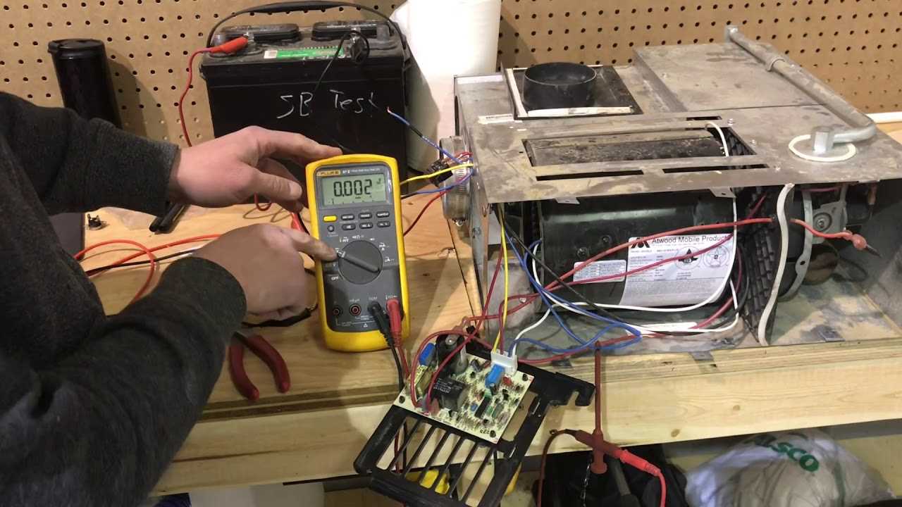
Long-term reliability of electrical connections is achieved through careful planning and attention to detail during installation. This includes using high-quality materials, such as durable connectors and corrosion-resistant components. In addition, following the manufacturer’s guidelines for electrical setups ensures that the system operates efficiently and remains safe throughout its lifespan. A well-executed connection plan not only maximizes performance but also minimizes the risk of unexpected
Ignition System and Safety Features
The ignition system plays a crucial role in ensuring efficient and reliable operation, while safety mechanisms are designed to protect both the equipment and its users. These two components work in tandem to guarantee proper performance and to minimize the risks associated with combustion-based systems.
The ignition process typically begins with a spark or electronic trigger, designed to safely initiate the heating cycle. Once the initial ignition occurs, the system carefully monitors the flame to ensure it remains stable. If any irregularities are detected, the safety mechanisms automatically shut down the system to prevent overheating or gas leaks.
Various sensors and controls are integrated into the system to detect malfunctions or dangerous conditions. These features include flame detectors, pressure switches, and temperature regulators, all designed to quickly react and deactivate the equipment if necessary. Regular maintenance and inspection are recommended to ensure that these safety features function as intended, helping to prolong the lifespan of the system and prevent potential hazards.
Air Circulation Path and Filters
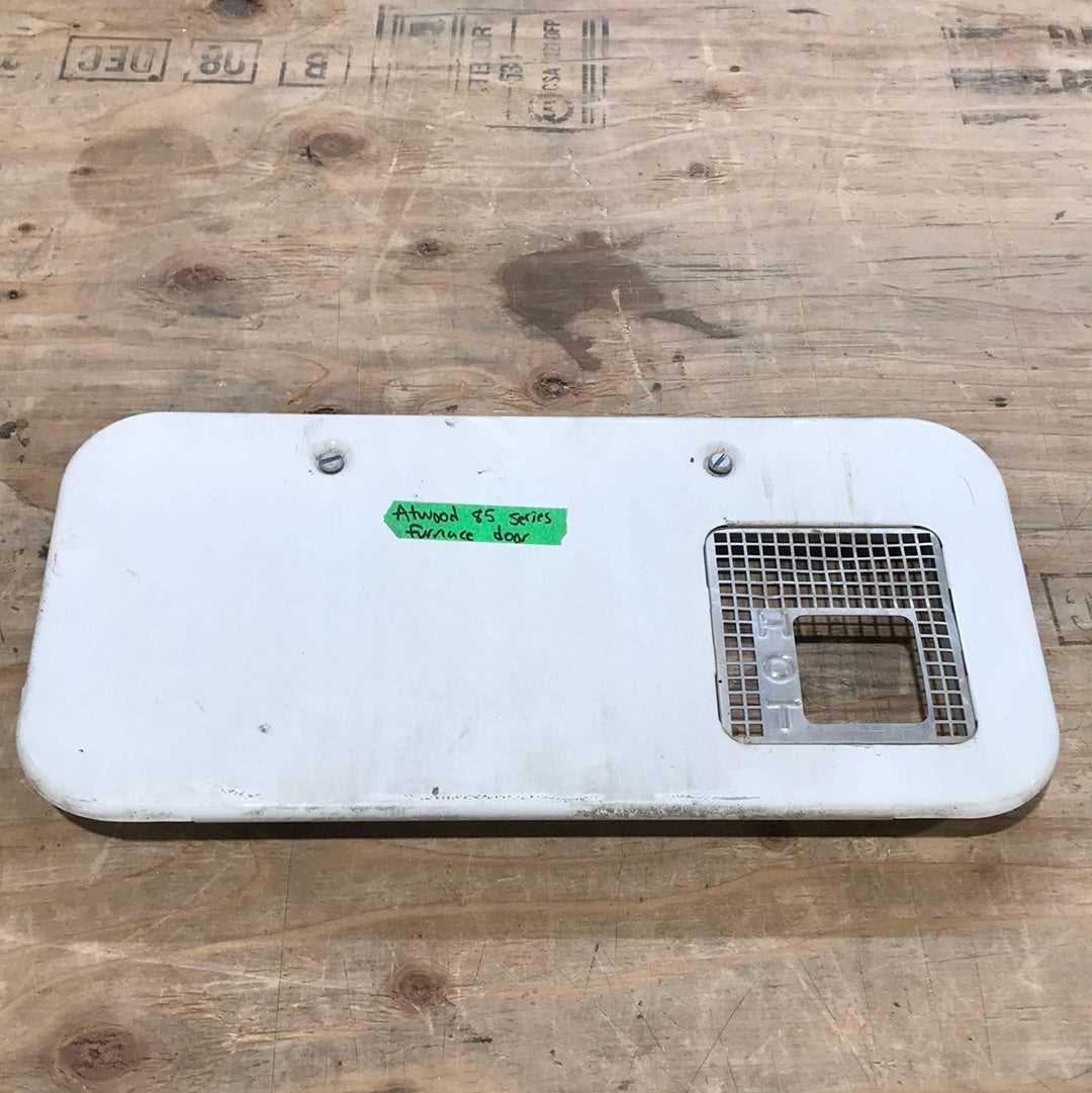
The proper movement of air through a heating system is crucial for efficient performance. Understanding the airflow route and the role of filters can help maintain a well-functioning unit, ensuring clean and consistent heat distribution. This section explores how air moves within the system and the importance of maintaining clean filters.
Airflow Path
Air travels through the system in a controlled manner, entering through intake vents, passing over heating elements, and then being distributed into the living spaces. Any obstruction along this path can reduce the efficiency of the system, making it important to regularly inspect the vents and internal components for blockages.
Filters and Their Role
Filters play a vital role in preventing dust, debris, and other contaminants from entering the system. Over time, these filters can become clogged, which restricts airflow and forces the system to work harder. Regular cleaning or replacement of filters ensures optimal airflow and helps prolong the lifespan of the equipment.
- Ensure intake vents are free from obstructions.
- Check filters monthly for signs of buildup.
- Replace filters according to manufacturer recommendations.
Maintenance Tips for Furnace Efficiency
Ensuring optimal performance of heating equipment is essential for maintaining comfort and minimizing energy costs. Regular upkeep not only enhances functionality but also extends the lifespan of the system. Implementing effective maintenance practices can lead to significant improvements in efficiency and reliability.
Regular Cleaning and Inspection
Routine cleaning of components is crucial for efficient operation. Dust and debris can accumulate, hindering airflow and causing the system to work harder. Schedule periodic inspections to identify and address any potential issues early on, including checking for wear and tear on essential elements.
Adjusting the Thermostat
Fine-tuning the thermostat settings can lead to noticeable savings. Ensuring that the temperature is set appropriately helps avoid unnecessary energy consumption. Consider investing in a programmable model that can adjust settings automatically based on your daily schedule, optimizing energy use without sacrificing comfort.
Troubleshooting Common Atwood 8500 Issues
When dealing with heating appliances, it is not uncommon to encounter various challenges that can affect their performance. Understanding potential problems and their solutions is essential for maintaining efficient operation. This section will outline some common issues faced by users, providing guidance on how to effectively address them.
Frequent Problems and Their Solutions
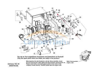
Users may experience several typical difficulties that can disrupt the heating process. Below is a summary of these issues along with corresponding solutions:
Issue Possible Causes Solutions Insufficient Heat Clogged vents, faulty thermostat Check for blockages and clean vents; calibrate or replace the thermostat. No Ignition Defective igniter, gas supply issues Inspect and replace the igniter; ensure gas supply is uninterrupted. Unusual Noises Loose components, fan malfunction Secure any loose parts; check and repair the fan assembly. Frequent Cycling Incorrect settings, airflow problems Adjust settings as needed; ensure proper airflow around the unit. Preventive Measures
Regular maintenance can significantly reduce the likelihood of experiencing issues. Periodic checks and cleaning can enhance performance and longevity. Consider establishing a maintenance schedule to ensure all components function optimally and any potential issues are addressed promptly.
Replacement Parts and Compatibility Guide
This section provides essential information regarding the interchangeable components and their compatibility for heating systems. Understanding which elements can be substituted or combined is crucial for effective maintenance and optimization of performance.
Identifying Compatible Components
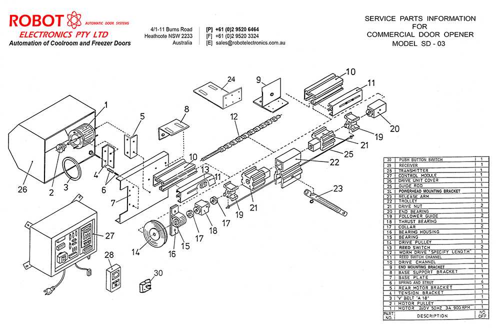
When selecting components, it is vital to consider specifications such as size, voltage, and type. Using the correct substitutes not only ensures proper functionality but also enhances safety and efficiency. Familiarize yourself with the key features to ensure that any replacements align with your heating system’s requirements.
Recommended Substitute Options
Below is a table of commonly used replacement options along with their compatibility notes to guide your selection process:
Component Type Recommended Substitute Compatibility Notes Igniter High-Temperature Igniter Ensure voltage rating matches original specifications. Blower Motor Universal Blower Motor Check mounting bracket for proper fit. Thermostat Digital Thermostat Verify compatibility with existing wiring setup. Control Board Replacement Control Module Match model number for seamless integration.