Yamaha YS624 Parts Breakdown and Assembly Guide
When it comes to maintaining and repairing mechanical systems, identifying each element and its function is crucial. This knowledge ensures the machine continues to operate at its full potential, minimizing downtime and improving efficiency. Each section has a unique role in the overall mechanism, contributing to smooth functionality and long-term durability.
Exploring the intricate connections between these elements offers deeper insight into how every part works together. Whether it’s the motor, drive system, or auger, knowing the layout of each component is essential for effective upkeep. With a clear breakdown of the layout, users can confidently address any issues that may arise, ensuring the equipment remains in optimal condition.
Having a clear and detailed view of the internal and external components allows for easier identification and replacement when necessary. This ensures that even the smallest parts are correctly aligned, contributing to the overall performance and reliability of the machine.
Yamaha YS624 Parts Diagram Overview
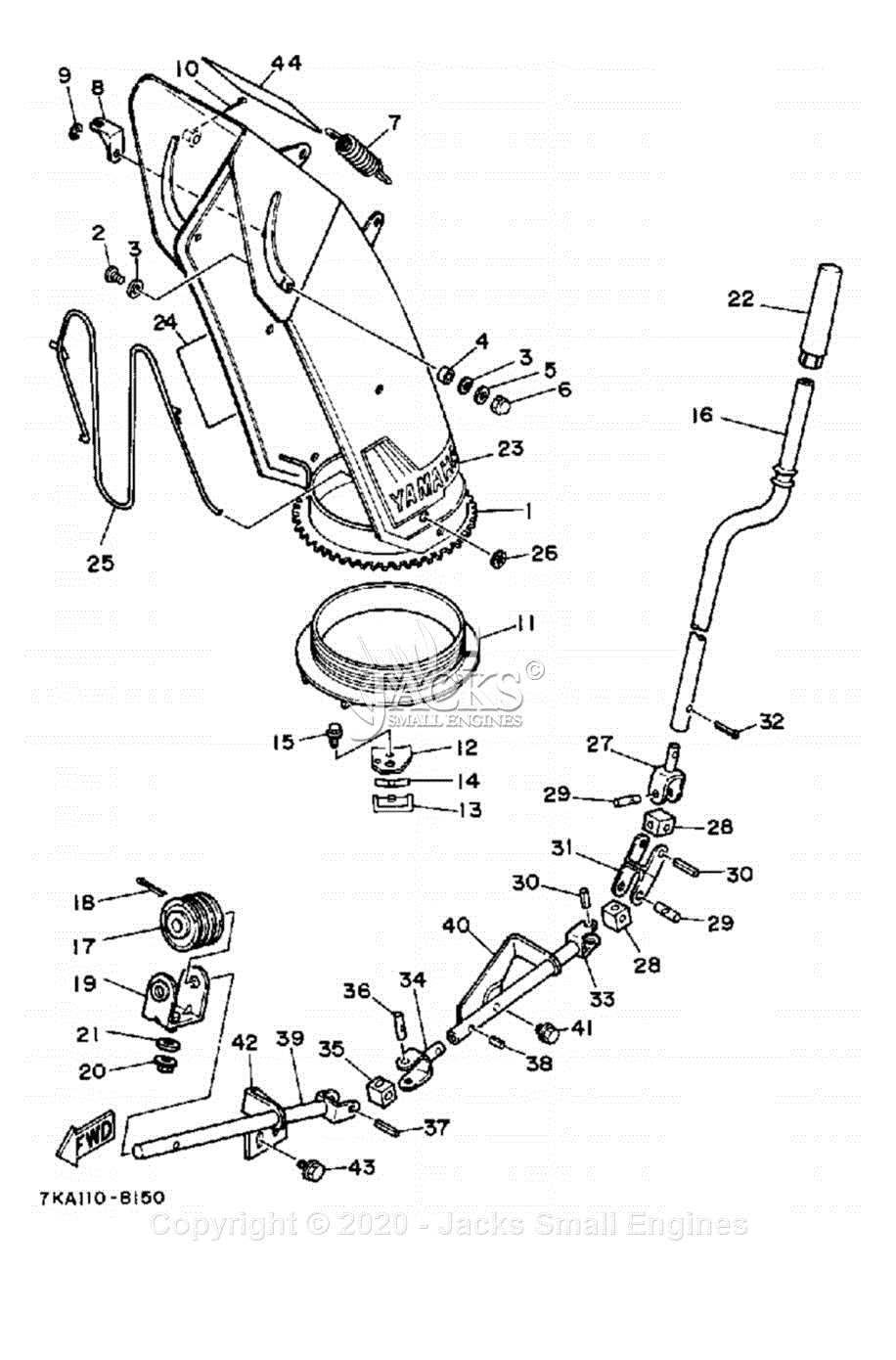
This section provides a clear breakdown of key mechanical components within a popular snow removal machine. The schematic simplifies understanding of how various elements are arranged and connected, offering insight into the inner workings and technical structure.
Key Mechanical Sections
The system is divided into distinct sections, each responsible for specific tasks. These sections include the driving mechanism, engine assembly, and blade housing, each serving a vital role in ensuring efficient operation during heavy-duty tasks. Understanding these areas helps users identify potential issues and maintain optimal performance.
Components and Their Functions
Below is a table listing essential elements along with their primary roles:
| Component | Function | |||||||||||||||||||||||||||||||||
|---|---|---|---|---|---|---|---|---|---|---|---|---|---|---|---|---|---|---|---|---|---|---|---|---|---|---|---|---|---|---|---|---|---|---|
| Engine Block | Provides power to drive the entire machine | |||||||||||||||||||||||||||||||||
| Transmission | Controls speed and movement across various terrains | |||||||||||||||||||||||||||||||||
| Component | Function |
|---|---|
| Clutch Assembly | Engages and disengages the power from the motor to the drivetrain. |
| Gearbox | Adjusts the output speed and torque based on user input and terrain conditions. |
| Drive Belt | Transfers rotational energy from the engine to the transmission system. |
| Axle | Provides stability and connects the wheels to the drivetrain, ensuring power is evenly distributed. |
Auger Mechanism and Blades Layout
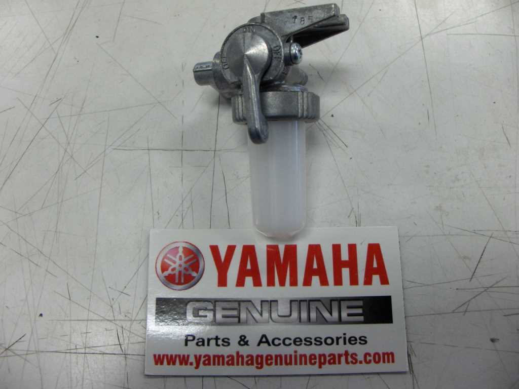
The system responsible for gathering and moving snow efficiently includes the rotating blades and the mechanism that powers them. This section outlines the arrangement and key components involved in the auger system, ensuring the smooth operation of snow removal equipment. Understanding the positioning of the blades and how the drive functions is crucial for maintaining optimal performance and longevity.
Main Components of the Auger System
In the auger system, several key elements work together to ensure efficient snow clearing. These include the spiral blades, which rotate to gather snow, and the central axle that powers the movement. Below is a simplified layout of the main components involved:
| Component | Description |
|---|---|
| Spiral Blades | Rotating blades that gather and direct snow towards the chute. |
| Central Axle | The shaft that drives the movement of the auger blades. |
| Bearings | Ensure smooth rotation of the blades around the axle. |
| Scrapers | Assist in removing snow from the surface during operation. |
Blade Arrangement and Function
The auger blades are positioned to maximize snow collection. The spiral design allows them to pull in snow from a wide area and direct it to the center, where it is discharged through the chute. The blades’ sharp edges cut through the snow, making the process quick and effective even in
Fuel and Exhaust Systems Explained
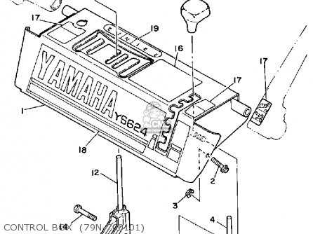
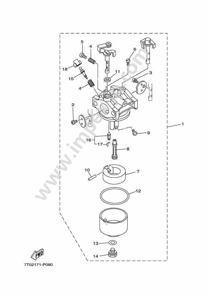
The efficient operation of an engine relies heavily on its fuel and exhaust systems. These components work together to ensure optimal performance, maintain energy output, and minimize harmful emissions. Understanding how these systems function and their individual parts is crucial for effective maintenance and troubleshooting.
Fuel System Components
The fuel system is responsible for delivering the right amount of fuel to the engine. Key components include:
- Fuel Tank: Stores the fuel before it reaches the engine.
- Fuel Pump: Transports fuel from the tank to the engine at the required pressure.
- Fuel Filter: Removes impurities from the fuel to protect engine components.
- Fuel Injectors: Atomize fuel for efficient combustion within the engine cylinders.
Exhaust System Functionality
The exhaust system plays a vital role in directing and treating exhaust gases produced during combustion. Its main components include:
- Exhaust Manifold: Collects exhaust gases from the engine cylinders.
- Catalytic Converter: Reduces harmful emissions through chemical reactions.
- Muffler: Silences the noise produced by the engine’s exhaust gases.
- Exhaust Pipes: Directs the treated gases away from the vehicle.
Regular inspection and maintenance of both systems can enhance engine efficiency, improve fuel economy, and prolong the life of the vehicle.
Chassis and Frame Structure
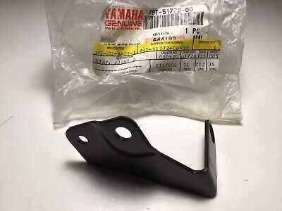
The chassis and frame play a crucial role in the overall performance and stability of any vehicle. This foundational structure supports the engine, transmission, and other vital components, ensuring that the vehicle operates smoothly and efficiently. A well-designed chassis contributes to better handling, durability, and safety, making it essential for both everyday use and specialized applications.
Typically crafted from robust materials, the frame is engineered to withstand various stresses while maintaining a lightweight profile. The design often incorporates strategic reinforcements to enhance rigidity and resistance to deformation. This careful balance of strength and weight is vital for achieving optimal performance, especially in dynamic conditions.
Additionally, the layout of the chassis influences the vehicle’s center of gravity, which directly affects its handling characteristics. Manufacturers often utilize advanced engineering techniques to optimize the geometry of the frame, resulting in improved agility and responsiveness during operation. Understanding these structural elements is fundamental for maintenance and upgrades, ensuring the vehicle remains reliable over time.
Drive and Wheel Components Overview
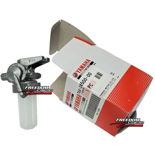
This section provides a comprehensive look at the essential elements that contribute to the functionality of the drive and wheel systems in various machines. Understanding these components is crucial for maintaining optimal performance and ensuring smooth operation.
Key Drive Components
- Transmission: Transmits power from the engine to the wheels, allowing for smooth acceleration and deceleration.
- Drive Shaft: A vital link that transfers rotational energy from the transmission to the wheels.
- Gearbox: Adjusts the torque and speed delivered to the wheels, enhancing control over the vehicle.
Wheel Assembly Elements
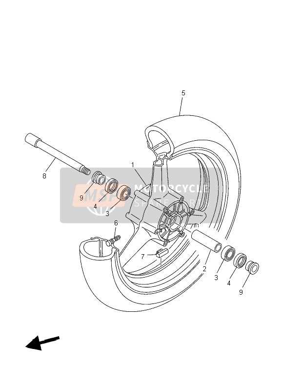
- Wheel Hubs: Central components that house the wheel bearings and connect the wheels to the drive system.
- Tires: The outer covering that provides traction and stability while interacting with the ground.
- Rims: The metal part of the wheel that supports the tire and maintains its shape under pressure.
Control Panel and Lever Functions
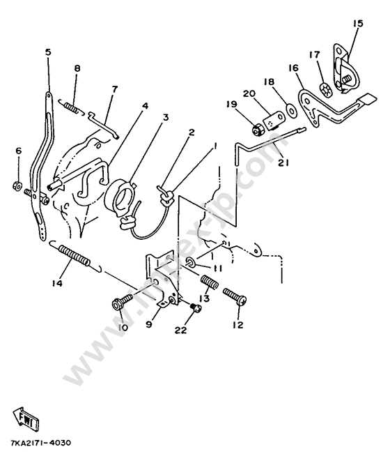
The control panel serves as the central interface for managing various functionalities of the machine. It incorporates a range of switches and indicators designed to provide users with intuitive control over operations, enhancing efficiency and ease of use.
Levers play a crucial role in facilitating manual adjustments and commands. Each lever is strategically positioned for quick access and serves specific purposes, such as engaging different operational modes or adjusting settings. Understanding the functions of these levers is essential for optimal performance and safety.
Indicators on the control panel are essential for monitoring system status and alerts. They provide real-time feedback, allowing users to make informed decisions while operating the equipment. This integration of controls ensures seamless interaction between the operator and the machinery.
Electrical System and Wiring Layout
The electrical system plays a crucial role in ensuring the efficient operation of machinery. It encompasses various components that work together to facilitate power distribution, control, and communication within the device. A comprehensive understanding of the wiring arrangement is essential for troubleshooting and maintenance.
Key elements of the electrical configuration include the power source, control units, and various sensors. These components are interconnected through a series of wires, which must be organized carefully to prevent malfunctions. Proper wiring layout not only enhances performance but also ensures safety by minimizing the risk of short circuits or electrical failures.
Additionally, color coding and labeling of wires aid in identifying connections and simplifying repairs. Regular inspection of the electrical system can help in detecting wear or damage, ensuring long-term reliability and functionality. Overall, a well-designed electrical framework is fundamental to the effective operation of the equipment.
Lubrication Points and Maintenance Areas
Ensuring the proper functionality of machinery involves regular attention to lubrication and maintenance areas. Identifying key locations for applying lubricant is essential for optimal performance and longevity. This section outlines critical zones where maintenance efforts should be focused, enhancing the overall efficiency of the equipment.
Lubrication points are typically found in areas where moving parts interact. These locations often include bearings, joints, and gears that require periodic application of grease or oil to minimize friction. Regular inspections should be conducted to assess the condition of these components and ensure that they are adequately lubricated.
In addition to lubrication, maintenance should also encompass cleaning and adjusting various parts. Dust and debris can accumulate in critical areas, potentially leading to operational issues. Therefore, it is vital to incorporate cleaning procedures into the maintenance routine. Checking for wear and tear on belts and chains, as well as ensuring proper tension, is also crucial for sustaining performance.
Lastly, keeping a detailed log of maintenance activities can help track the service history and anticipate future needs. Following a systematic approach to lubrication and upkeep will ultimately lead to enhanced reliability and reduced downtime.
Replacing and Upgrading YS624 Parts
Maintaining optimal performance and functionality in your equipment often involves the timely replacement or enhancement of various components. Understanding the significance of upgrades and the process of exchanging worn-out elements can lead to improved efficiency and longevity.
When considering modifications, it’s essential to evaluate the compatibility of new components with existing systems. Selecting quality replacements not only ensures smooth operation but can also enhance features, resulting in a better overall experience. Here is a table that outlines some common components to consider for upgrades or replacements:
| Component | Description | Benefits of Replacement/Upgrade |
|---|---|---|
| Engine | Key power source that drives the machinery. | Increased power output and efficiency. |
| Transmission | Transmits power from the engine to the wheels. | Smoother gear shifts and improved handling. |
| Wheels | Crucial for mobility and traction. | Enhanced grip and performance in various conditions. |
| Brakes | Essential for stopping and control. | Better safety and responsiveness. |
Before initiating any changes, it’s advisable to consult the manufacturer’s guidelines and specifications to ensure that all modifications meet safety standards and compatibility requirements.
