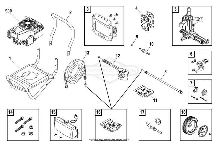
Briggs and Stratton 900 Series Parts Diagram Guide
briggs and stratton 900 series parts diagram

Understanding the internal structure of small engines can be crucial for maintaining optimal performance. Whether you are a seasoned mechanic or a DIY enthusiast, having a clear view of how everything fits together helps in diagnosing and fixing issues more efficiently. This guide provides a detailed examination of the essential mechanical elements found in popular engines, allowing for better maintenance and repair practices.

Key features of these systems include various moving and stationary elements, each playing a critical role in ensuring smooth operation. By breaking down the core components, this guide aims to offer valuable insights into how the engine functions and how its various sections interact to power different types of machines.

Whether you are dealing with issues related to the fuel system, ignition, or cooling mechanisms, understanding the role of each component is vital. This resource will help you gain a deeper knowledge of the individual elements, enabling more efficient troubleshooting and repair work on your engine.

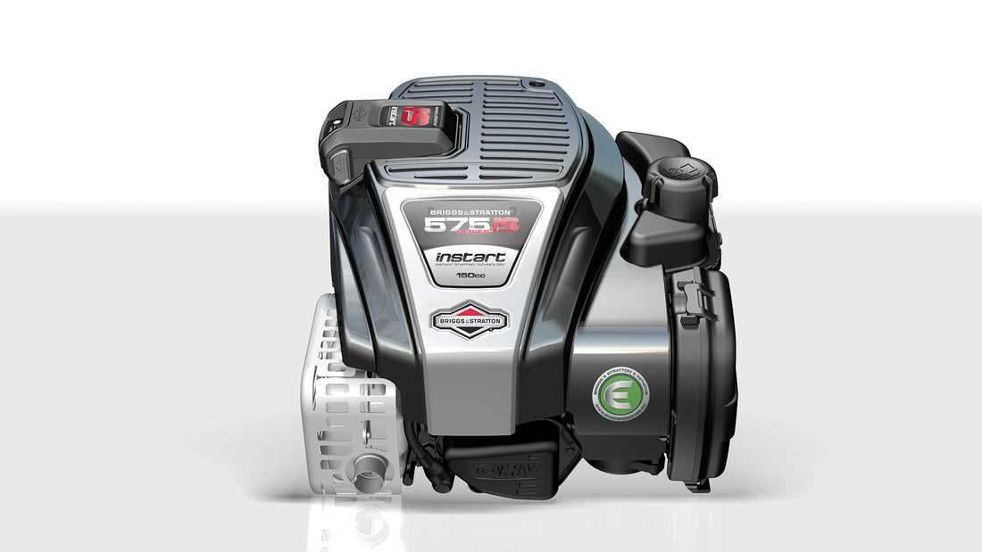
Understanding the Briggs and Stratton 900 Series Engine

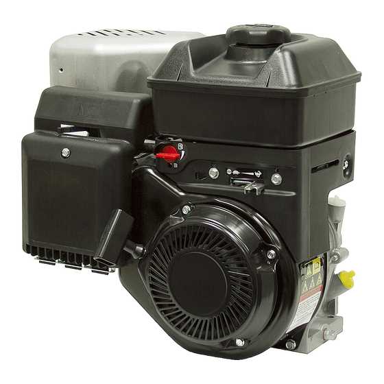
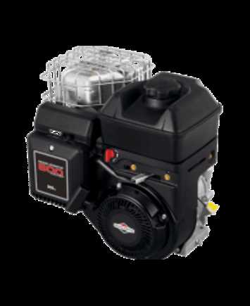
The engine in question is a reliable power source often utilized in various outdoor equipment. It is known for its durability, efficiency, and smooth operation, making it a popular choice for those seeking consistent performance. Designed with precision, it offers the right balance between power output and fuel efficiency, ensuring machines run optimally over long periods of use. Whether you are maintaining a lawn or operating other machinery, this engine serves as a dependable component, offering both strength and reliability.

With a well-thought-out design, the engine’s configuration allows for easy maintenance and repair. The internal components are engineered to provide longevity, reducing the need for frequent replacements. Operators appreciate how the engine delivers dependable operation even under demanding conditions, helping users get the most out of their equipment. For those interested in its inner workings, understanding its features and layout is crucial for maximizing its potential.

Key Components and Their Functions

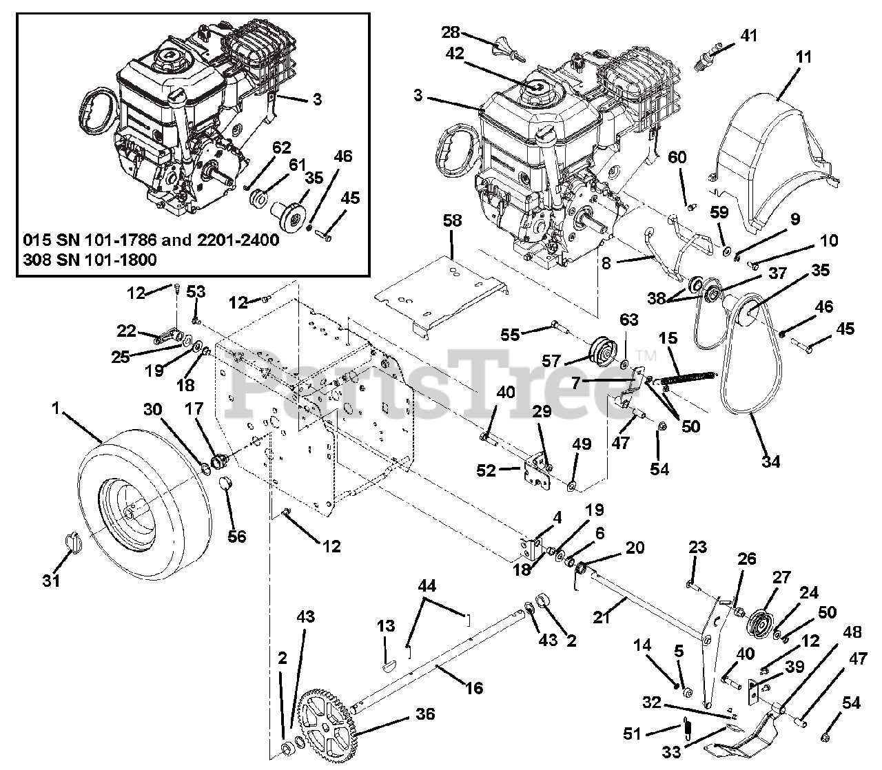
The internal mechanics of small engines rely on various essential elements that work in unison to ensure efficient operation. Each component has a specific role, contributing to the engine’s overall performance and durability. Understanding these elements allows users to diagnose issues and maintain the machine effectively.

Engine Block and Cylinder

The engine block serves as the foundation for the entire system. It houses critical parts such as the cylinder, where fuel combustion takes place. The cylinder’s purpose is to channel the energy created by combustion into mechanical power that drives the machine.

Ignition and Fuel System
briggs and stratton 900 series parts diagram

The ignition system is responsible for initiating the combustion process. It consists of elements like the spark plug, which creates the necessary spark to ignite the fuel mixture. The fuel system, on the other hand, ensures that the correct amount of fuel is supplied to the cylinder for combustion.

Exploring the Carburetor Assembly Diagram

briggs and stratton 900 series parts diagram

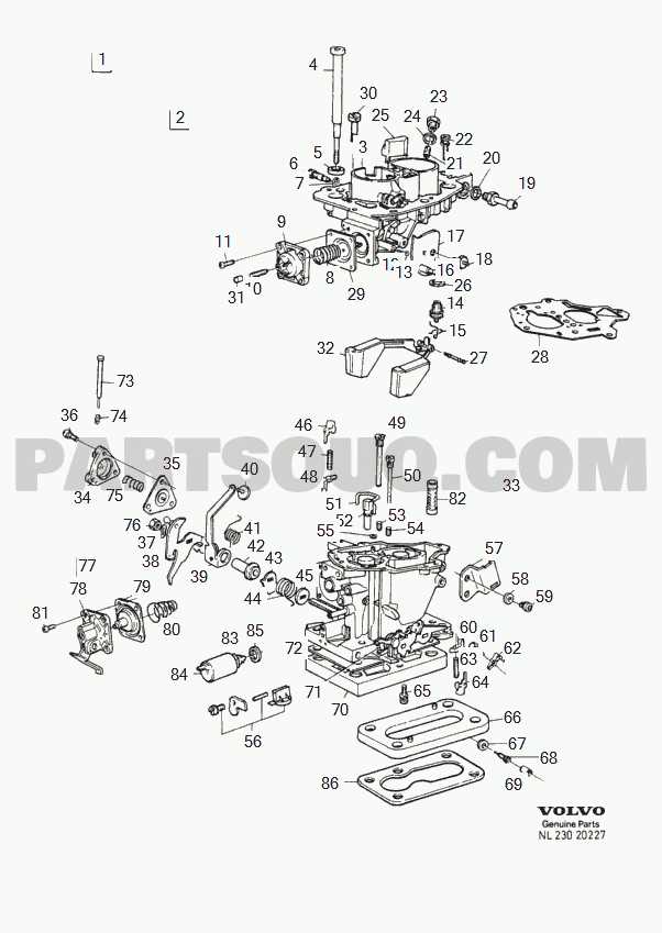
The carburetor is a crucial component in any engine, playing a vital role in the regulation of fuel and air mixture. Understanding the structure of this component helps in maintaining the efficiency and performance of the system. By analyzing its assembly layout, you can gain insights into how various parts work together to ensure smooth operation.

Main Components Overview

At the core of the carburetor assembly are several essential parts. These include the fuel bowl, throttle valve, choke, and jets. Each component has a specific function in regulating fuel flow and air intake, ensuring the engine runs efficiently under different conditions. Understanding the placement and role of these elements is key to diagnosing performance issues.

Detailed Component Breakdown

briggs and stratton 900 series parts diagram

Component Function
Crankshaft
Fuel System Parts and Connections

The fuel delivery setup plays a crucial role in ensuring efficient engine performance. It consists of various components working together to store, transfer, and regulate the flow of fuel to the engine, allowing it to run smoothly. Understanding the key elements of this system helps maintain optimal operation and addresses potential issues effectively.

  • Fuel Tank: The container responsible for holding the fuel, providing a steady supply to the rest of the system.
  • Fuel Line: Connects the tank to the engine, ensuring a consistent flow of fuel through a flexible or rigid pipe.
  • Fuel Filter: Cleans the fuel by removing any impurities before it reaches the engine, protecting sensitive parts from damage.
  • Fuel Pump: Ensures that fuel is delivered under the correct pressure, helping the engine receive the appropriate amount needed for combustion.

  • Ignition System and Related Components

    briggs and stratton 900 series parts diagram

    The ignition mechanism plays a crucial role in ensuring proper engine performance by controlling the spark needed for combustion. This section explores the essential components that work together to generate the necessary electrical charge to ignite the fuel mixture, thus enabling smooth operation. Understanding how each part functions is key to maintaining and troubleshooting the overall engine system.

    Spark Plug and its Role

    briggs and stratton 900 series parts diagram

    The spark plug is a central element in the ignition process, responsible for delivering the high-voltage charge from the coil to ignite the air-fuel mixture in the combustion chamber. Its condition directly influences the efficiency of the engine, with worn or damaged plugs often leading to misfires or reduced performance.

    Ignition Coil Functionality

    The ignition coil transforms low battery voltage into the high voltage required to create an electric spark in the spark plug. This component is essential for proper ignition timing and ensures that the engine

    Overview of the Air Intake System

    briggs and stratton 900 series parts diagram

    The air intake mechanism plays a crucial role in the overall performance of small engines. This system is responsible for drawing in atmospheric air, which is essential for the combustion process. A well-designed intake system ensures that the engine receives the optimal amount of air, contributing to efficient fuel combustion and effective engine operation.

    Components of the Air Intake System

    The air intake system consists of several key elements, including the air filter, intake manifold, and carburetor. Each component has a specific function that contributes to the efficient delivery of air to the combustion chamber. The air filter serves to remove contaminants from the incoming air, preventing damage to the engine. The intake manifold directs the clean air towards the carburetor, where it mixes with fuel before entering the combustion chamber.

    Importance of Maintenance

    Regular maintenance of the air intake system is vital for optimal engine performance. A clogged or dirty air filter can restrict airflow, leading to poor engine performance and increased fuel consumption. Additionally, ensuring that all components are in good condition can prevent air leaks and maintain the correct air-fuel mixture for efficient combustion. Neglecting the air intake system can result in reduced engine efficiency and increased emissions.

    Oil System Parts and Maintenance

    briggs and stratton 900 series parts diagram

    The lubrication system is a critical component in ensuring the smooth operation and longevity of small engines. Proper maintenance of this system helps prevent wear and tear, ultimately enhancing performance and reliability. Understanding the various elements involved in the lubrication process is essential for effective upkeep.

    Lubrication Components include the oil pump, filter, and various hoses and fittings. The oil pump circulates lubricant throughout the engine, ensuring that all moving parts receive adequate coverage. Filters play a crucial role in trapping contaminants, thereby maintaining the integrity of the lubricant. Regular inspection and timely replacement of these components can significantly extend the engine’s lifespan.

    Maintenance Practices should include checking oil levels frequently and changing the lubricant according to the manufacturer’s recommendations. It’s vital to use the correct type of lubricant, as specified in the engine’s manual, to optimize performance. Additionally, monitoring for any leaks or unusual noises can help identify potential issues before they escalate.

    By prioritizing the upkeep of the lubrication system, users can ensure that their engines operate efficiently and effectively, minimizing the risk of premature failure.

    Detailed Breakdown of the Crankshaft Assembly

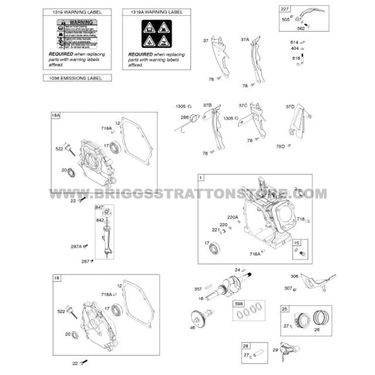
    The crankshaft assembly is a critical component in the engine’s operation, serving as the main link between the engine’s power generation and its mechanical functions. Understanding its structure and individual components is essential for proper maintenance and repairs.

    Key Elements of the Crankshaft Assembly consist of various parts, including the crankshaft itself, bearings, and connecting rods. Each of these components plays a vital role in ensuring the smooth rotation and efficient functioning of the engine.

    The crankshaft is the central element, converting linear motion from the pistons into rotational motion. This transformation is crucial for driving the various accessories attached to the engine. Bearings support the crankshaft, allowing for smooth rotation while minimizing friction and wear. Additionally, connecting rods link the crankshaft to the pistons, translating their movement into the rotational force required for the engine’s performance.

    Regular inspection of the crankshaft assembly is recommended to identify any wear or damage. Proper lubrication and timely replacement of worn components are essential practices to ensure optimal engine performance and longevity.

    Cooling System and Its Importance

    The cooling mechanism plays a crucial role in maintaining the optimal performance of small engines. Its primary function is to regulate the temperature, preventing overheating during operation. An efficient cooling setup ensures the longevity of components and enhances overall efficiency.

    A well-functioning cooling system utilizes various components, including radiators, fans, and coolant channels, to dissipate heat generated by the engine. Heat management is essential not only for performance but also for safety. When temperatures exceed normal levels, it can lead to severe damage, including engine failure.

    Moreover, proper cooling contributes to fuel efficiency. When an engine operates at the right temperature, it burns fuel more effectively, leading to reduced emissions and improved overall efficiency. Therefore, understanding the cooling system’s function is vital for anyone maintaining or repairing these types of engines.

    Gasket and Seal Replacement Guide

    Maintaining optimal performance of your engine requires attention to detail, particularly when it comes to the replacement of gaskets and seals. These components play a crucial role in preventing leaks and ensuring that fluids remain contained within the system. This guide aims to provide essential information for effectively replacing these parts, helping you maintain the integrity of your machinery.

    Identifying Gaskets and Seals

    Before you begin the replacement process, it is important to identify the various gaskets and seals in your engine. Common types include:

    • Oil seals
    • Intake gaskets
    • Exhaust gaskets
    • Head gaskets

    Replacement Process

    briggs and stratton 900 series parts diagram

    Follow these steps for a successful replacement:

    1. Gather necessary tools, including a scraper, torque wrench, and sealant.
    2. Carefully remove the old gasket or seal, taking care not to damage surrounding surfaces.
    3. Clean the surfaces thoroughly to ensure proper adhesion of the new component.
    4. Install the new gasket or seal, ensuring it is aligned correctly.
    5. Reassemble any removed components and tighten bolts to the manufacturer’s specifications.

    Troubleshooting Common Issues with Diagrams

    Identifying and resolving issues in machinery can often be challenging, particularly without clear visual aids. Utilizing detailed schematics significantly enhances the troubleshooting process, providing insights into component relationships and functionality. This section aims to highlight typical problems that may arise, accompanied by illustrative representations to aid in effective resolution.

    Common Problems and Solutions

Component Function
Fuel Bowl Stores fuel before it is mixed with air.
Throttle Valve Controls the amount of air entering the engine.
Issue Description Recommended Action
Starting Failure Engine does not initiate when attempting to start. Check fuel levels, inspect the ignition system, and examine the battery condition.
Overheating Unit becomes excessively hot during operation. Ensure proper ventilation, check coolant levels, and inspect for debris blocking airflow.
Uneven Performance Machine operates inconsistently, with fluctuations in speed. Inspect the carburetor settings, air filter, and spark plug condition for wear.
Excessive Vibration Unit exhibits unusual shaking during operation. Check for loose components and ensure that all parts are securely fastened.

Visual Aids for Effective Troubleshooting

Visual aids can be invaluable in pinpointing the source of issues. By referencing accurate schematics, operators can track down specific components that may be malfunctioning. Understanding the layout allows for quicker identification of problems, reducing downtime and facilitating efficient repairs.