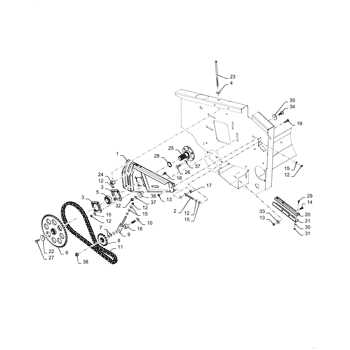
| Power Unit |
Generates the required force
Functionality of the Auger System
The rotating mechanism responsible for gathering and moving materials is a key component in ensuring efficient operation in various conditions. This system plays a critical role in handling different types of debris, moving them to another part of the equipment for further processing. By breaking down and guiding materials, the mechanism ensures a continuous flow, preventing blockages and maintaining overall performance.
The structure is designed to withstand harsh environments, ensuring reliability even under heavy loads. Its movement pattern is precisely engineered to maximize efficiency, directing materials efficiently without overworking the system. This balance of power and precision enables smooth operation, providing consistent performance regardless of external factors.
Importance of the Impeller and Fan
The impeller and fan play a crucial role in the efficient functioning of various machinery designed to handle debris, air, or other materials. These components work together to ensure proper movement and disposal, optimizing performance and minimizing blockages or inefficiencies.
The impeller is responsible for generating the force needed to move material through the system. Its blades spin at high speed, propelling material forward and preventing it from clogging up the pathway. Meanwhile, the fan enhances airflow, further improving the overall function and reducing the risk of overheating or reduced performance.
- Enhanced Efficiency: By optimizing the flow of materials, the impeller and fan reduce energy consumption and ensure smooth operation.
- Prevention of Blockages: These components help maintain a clear path, minimizing downtime caused by clogs or jams.
- Temperature Control: The fan regulates airflow, preventing overheating during extended use and preserving the system’s longevity.
Regular maintenance and inspection
Transmission and Gearbox Breakdown
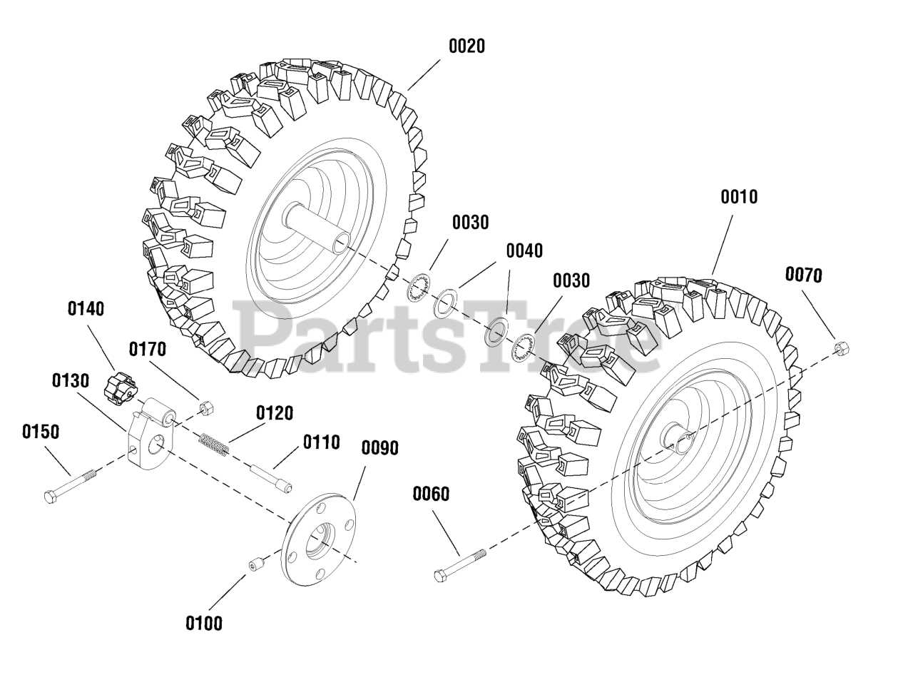
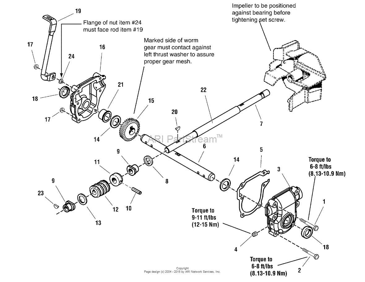
Understanding the internal mechanisms of the transmission and gearbox is essential for optimal performance and maintenance. These components work together to control power distribution, ensuring the machine operates efficiently under various conditions. By examining the structure and function of each part, users can make informed decisions regarding upkeep and repairs.
The transmission system is responsible for transferring energy from the engine to the wheels, while the gearbox adjusts the speed and torque output. Both systems rely on precise interaction between gears, shafts, and other key elements. Below is a detailed breakdown of the transmission and gearbox components:
| Component |
Function |
Electrical Wiring and Safety Features
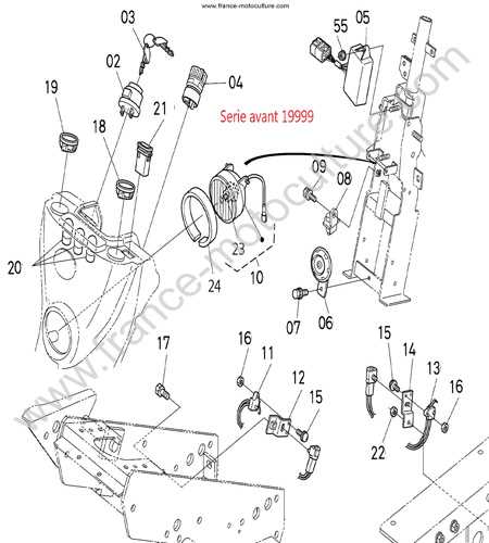
Understanding the electrical system and its integrated safety mechanisms is essential for maintaining the reliability and safe operation of equipment. Proper wiring not only ensures efficient performance but also plays a critical role in preventing potential hazards.
Key Components of Electrical Wiring
- Wiring Harness: A structured network that connects various electrical elements, ensuring power is distributed efficiently.
- Fuses and Relays: Essential for protecting the system from overloads or short circuits by interrupting the flow of current when necessary.
- Connectors: Specialized joints that secure different parts of the electrical circuit, preventing accidental disconnections or power failures.
Control Levers and Adjustment Mechanisms
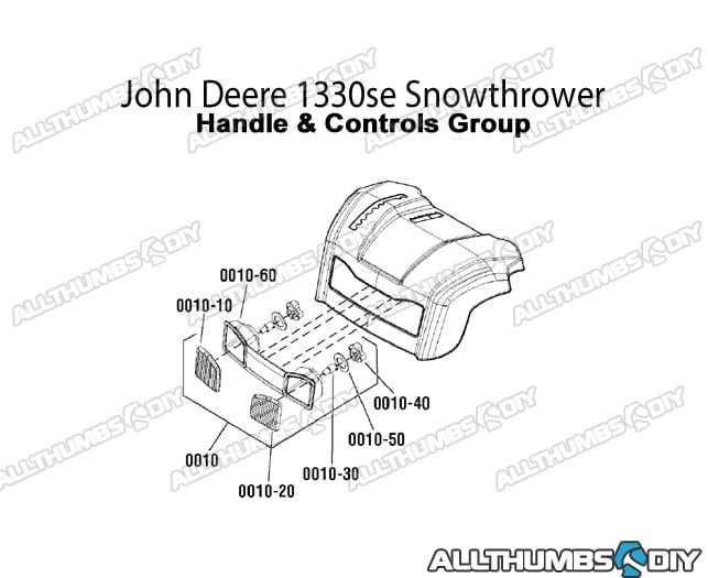
The various control levers and adjustment mechanisms are essential for ensuring precise operation and ease of use in complex machines. These components allow users to manage and modify functions, making it easier to adapt to different conditions or preferences during operation. Understanding the purpose of each lever and how to adjust them properly can enhance both performance and safety.
Below is an overview of the common control levers and their associated adjustment mechanisms:
| Lever |
Function |
Adjustment Process |
| Drive Control |
Eng
Snow Chute and Deflector Parts
The chute and deflector system is an essential component in any machine designed for handling winter conditions. This assembly controls the direction and height of the material being expelled, allowing for efficient clearing and precise adjustments based on the terrain or target area. Proper maintenance and adjustment of these elements ensure smooth operation and minimize clogging, which can improve the overall performance of the equipment.
Chute Mechanism
The chute mechanism typically consists of a rotating structure that directs the expelled material. It is important to ensure the rotation system is functioning correctly, as a malfunction can lead to improper distribution. Regular inspection of the rotating gears and the base can prevent wear and tear, helping maintain optimal control over direction.
Maintenance of the Skid Shoes
Proper care of the skid shoes is essential for ensuring smooth and even operation on various surfaces. Regular inspection and adjustments can significantly extend their lifespan, reducing wear and tear during use. This section covers essential steps to maintain these components in optimal condition.
- Inspect the skid shoes for signs of uneven wear. Replace them if the surface appears worn or damaged.
- Check the height adjustment regularly, making sure that it matches the surface type to avoid scraping or digging into the ground.
- Lubricate the bolts and fasteners periodically to ensure easy adjustments and prevent rust from forming.
- Ensure that both sides are level to prevent uneven wear on one side, which
Evaluating the Tires and Wheel Assemblies
When assessing the mobility and overall functionality of a clearing machine, the condition and quality of the tires and wheel systems play a crucial role. These components ensure proper grip and stability, affecting performance on various surfaces and under different weather conditions. It is important to regularly check the wear and tear of these parts to maintain optimal operation.
Factors to Consider for Tire Evaluation
- Traction: Assessing the tread pattern and depth helps determine the traction on different terrains.
- Inflation: Proper air pressure is essential for efficient operation and tire longevity.
- Damage: Check for punctures, cuts, or any signs of uneven wear that could compromise performance.
- Durability: The material quality affects the tire’s resistance to harsh conditions and rough surfaces.
Inspecting Wheel Assemblies
- Alignment: Ensuring the wheels are properly aligned prevents uneven wear and enhances maneuverability.
- Wheel Condition: Look for rust, cracks, or deformities that may cause instability or performance issues.
- Maintenance: Regular cleaning and lubrication of the wheel components help prolong their lifespan and functionality.
Replacement of Belts and Pulleys
When it comes to maintaining the efficiency of your equipment, the proper functioning of drive belts and pulleys is essential. These components play a critical role in transferring motion and power, making them prone to wear and tear over time. Regular inspection and timely replacement can prevent unexpected malfunctions and ensure smooth operation during heavy-duty tasks.
To begin the replacement process, first identify the specific belt and pulley system used in your machinery. Depending on the model, these parts may vary in size and configuration. Always refer to the manufacturer’s guidelines to select the correct replacement parts, ensuring a proper fit and optimal performance.
| Component |
Purpose |
Replacement Interval |
| Drive Belt |
Transfers power from the engine to moving parts. |
Check every 100 hours of operation or annually. |
| Pulleys |
Guide and adjust the direction of the drive belt. |
Inspect regularly for wear and replace as needed. |
| Tensioner |
Maintains appropriate tension on the drive belt. |
Replace if damaged or unable to maintain tension. |
When replacing these components, it is vital to ensure they are correctly aligned to avoid excessive wear. Misalignment can lead to faster degradation of belts and pulleys, reducing the overall lifespan of your equipment. After installation, always test the system for proper functionality before resuming use.
Lubrication and Fluid Systems Explained
The effective functioning of mechanical systems relies heavily on proper lubrication and fluid management. These systems are essential for reducing friction, preventing wear, and ensuring smooth operation of components. Without adequate maintenance of lubricants and fluids, machinery can experience excessive damage, leading to decreased performance and costly repairs.
Types of Lubricants and Fluids
There are various types of lubricants and fluids used depending on the specific needs of the equipment. These include:
- Engine oil – used for internal combustion engines to reduce friction between moving parts.
- Hydraulic fluid – responsible for transferring power within hydraulic systems.
- Grease – often used for parts that are exposed to heavy loads and require additional protection against wear and water damage.
- Coolants – used to regulate temperature and prevent overheating of engines and components.
Proper Fluid Maintenance
Maintaining the correct levels of lubricants and fluids is crucial for the longevity and efficiency of machinery. Follow these steps for proper upkeep:
- Regularly check fluid levels and add more if necessary.
- Replace fluids according to the manufacturer’s recommendations.
- Inspect the system for leaks and seal any that may occur.
- Ensure the use of the correct type of lubricant or fluid as specified for each component.
Common Troubleshooting for Snowblower Issues
When operating a winter clearing machine, occasional malfunctions can occur, leading to inefficiency or complete failure. Identifying the root cause of issues such as poor performance or mechanical failure is essential for efficient repairs. Here, we will explore common problems faced during operation and their possible solutions.
Common Problems and Solutions
Several issues can cause a clearing machine to stop functioning correctly. Below are some common malfunctions along with their suggested fixes:
| Problem |
Possible Cause |
Suggested Solution |
| Engine won’t start |
Empty fuel tank or stale fuel |
Refill with fresh fuel and ensure the tank is sealed properly |
| Lack of power |
Clogged air filter or faulty spark plug |
Clean or replace the air filter and check the spark plug |
| Frozen auger |
Built-up ice or snow blocking the auger |
Clear any obstructions and apply lubricant to moving parts |
Maintenance Tips for Longevity
To prevent common issues, regular maintenance is essential. Ensuring the machine is clean and lubricated will help keep it running smoothly during the harshest conditions. Always check for wear and tear on critical components before and after each use.
|
|
