Comprehensive Guide to Wisconsin Engine Parts Diagram
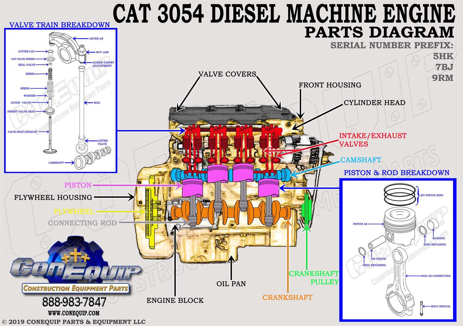
In this segment, we delve into the intricate framework of a mechanical illustration, dissecting its interconnected components and the dynamic relationships they establish. Each element plays a crucial role, contributing to the operational synergy that defines the functionality of this visual guide.
Unveiling the underlying structure, we uncover a labyrinth of interconnected pathways, each serving a distinct purpose. This portrayal of mechanical interaction transcends the static, offering a vivid depiction of motion and alignment.
Through careful examination, we navigate the integrated network of pathways and junctions, deciphering the narrative woven within. This exposition celebrates the artistry of technical illustration, illustrating the harmonious dance of functionality and form.
Understanding the Wisconsin Engine Parts Diagram
Grasping the layout of a power unit’s components is essential for effective maintenance and repair. This knowledge not only facilitates troubleshooting but also enhances overall performance. Each segment plays a crucial role in ensuring smooth operation, making it vital to recognize how they interconnect.
Key Components and Their Functions
Various elements contribute to the functionality of the machine. The ignition system initiates combustion, while the fuel delivery mechanism ensures optimal energy supply. Understanding these individual roles aids in identifying potential issues and streamlining repairs. Regular familiarity with these components can lead to increased efficiency and longevity.
Interconnections and Maintenance Tips
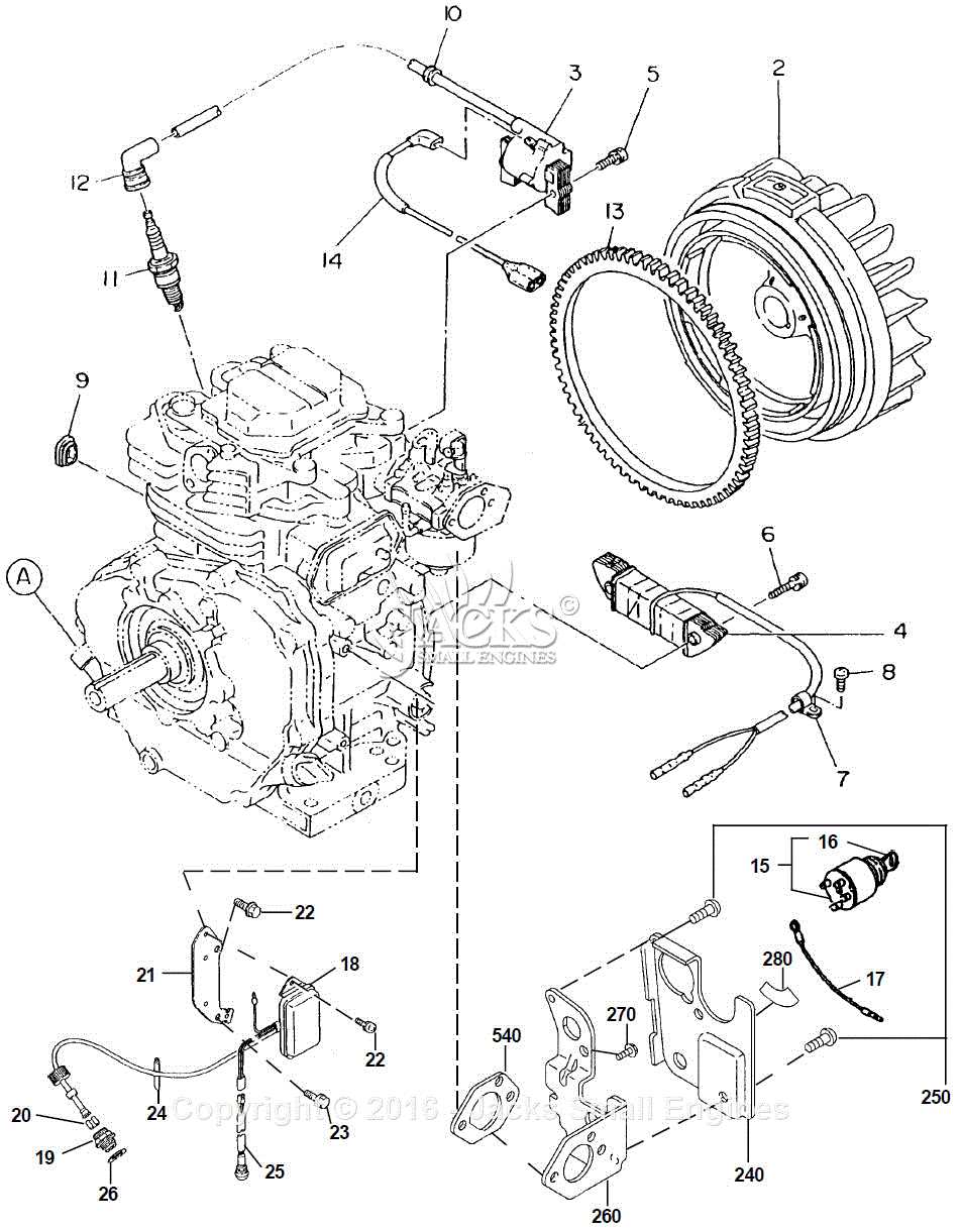
The relationship between different segments is intricate. Regular checks on the alignment and condition of these parts can prevent significant breakdowns. Keeping a detailed record of any discrepancies or changes will further assist in maintaining peak performance. By recognizing how each piece works together, users can better anticipate maintenance needs and make informed decisions.
Overview of Engine Components
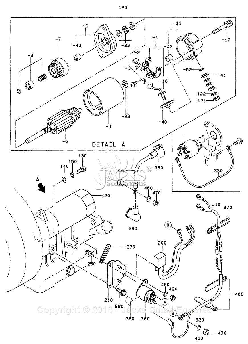
This section provides an insightful look into the various elements that constitute a power-generating unit. Understanding these components is essential for grasping how they interact to deliver optimal performance. Each segment plays a crucial role in the overall functionality, and their collaboration ensures efficient operation.
Main Elements
The primary components include the assembly responsible for combustion, the mechanisms that facilitate movement, and the systems that regulate temperature and pressure. Each part has a specific function that contributes to the smooth operation of the whole unit. The design and materials used in these elements can significantly affect performance and durability.
In addition to the main constituents, supporting systems such as lubrication, cooling, and ignition are vital. These systems enhance efficiency and longevity by minimizing wear and tear. A comprehensive understanding of these auxiliary mechanisms provides deeper insight into maintenance and troubleshooting, ensuring reliability in operation.
Importance of Understanding Parts
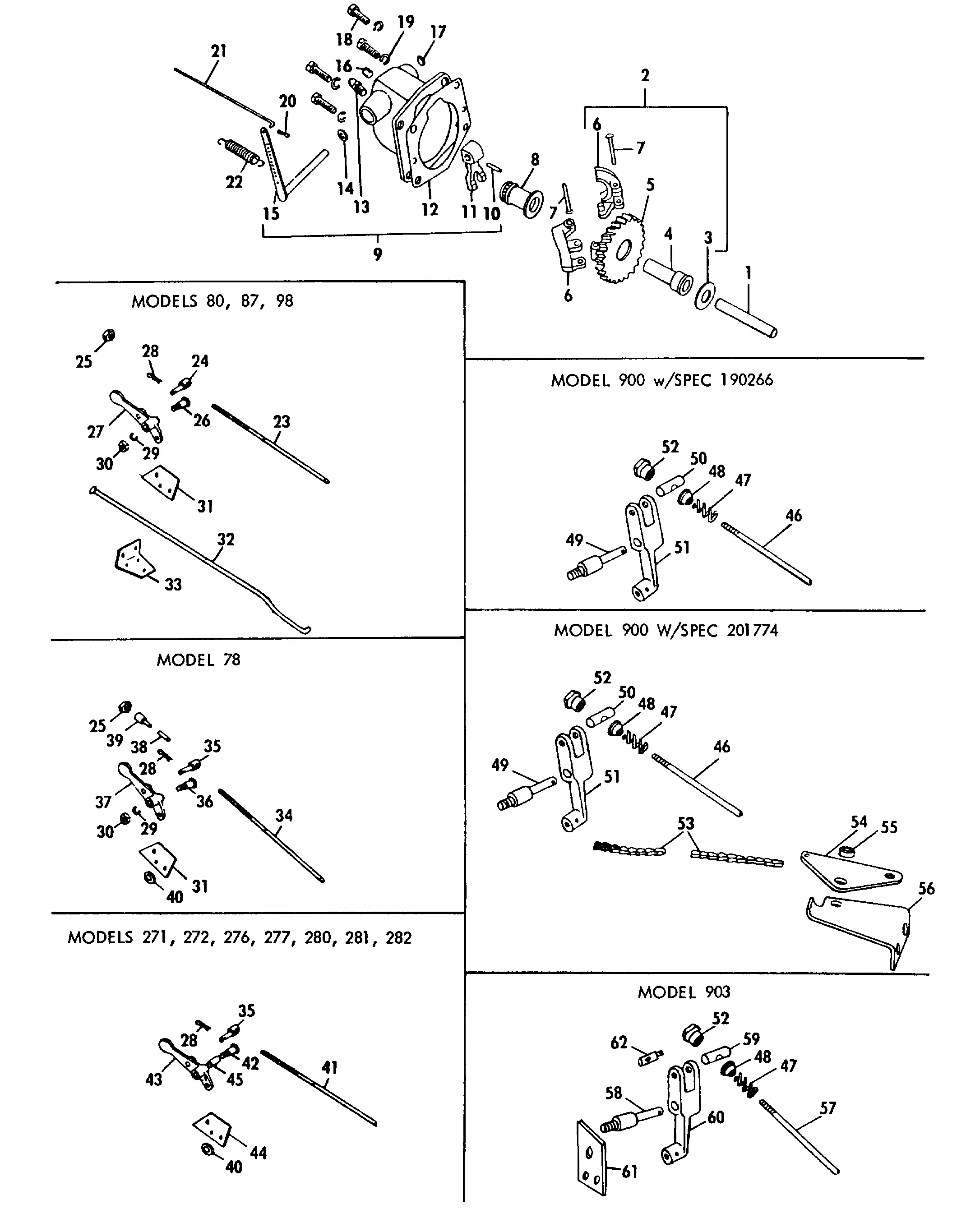
Having a clear grasp of how components work together is essential for maintaining and repairing mechanical systems. When you know the role of each element, it becomes easier to identify issues and ensure everything functions smoothly.
Recognizing individual pieces allows you to make informed decisions, whether you are performing maintenance or sourcing replacements. This knowledge helps avoid costly mistakes and keeps equipment running efficiently.
Learning about each piece also enhances safety, as improper handling or installation can lead to malfunction. A solid understanding ensures that each step in the process is completed correctly.
Locating Key Components in Diagram
Understanding the layout of essential elements within a schematic is crucial for effective troubleshooting and maintenance. Identifying where each component is positioned can facilitate faster repairs and enhance overall performance. This section aims to guide readers in recognizing and locating significant features within the visual representation.
Start by familiarizing yourself with the overall structure, noting how the components are arranged. Look for labels and symbols that indicate functionality, as these often provide insight into the role each part plays. Pay attention to any connecting lines or pathways, which can signify relationships and interactions between the various elements.
Additionally, consider using a color-coded system if available, as this can help differentiate between various types of components, such as electrical or mechanical. By taking the time to study the layout and organization, you will develop a clearer understanding of the system, leading to more efficient diagnostics and maintenance efforts.
Exploring Internal Components
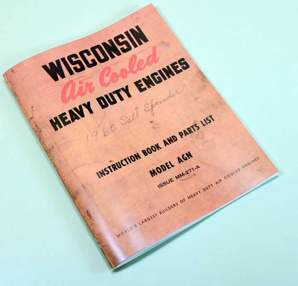
Understanding the inner workings of mechanical systems is essential for anyone looking to enhance performance or troubleshoot issues. This section delves into the various elements that contribute to the functionality and efficiency of these complex mechanisms.
Key Elements of Functionality
Several fundamental components play a critical role in the overall operation. Each element works in harmony to ensure smooth performance. Below are some of the vital features to consider:
- Crankshaft: This crucial part converts linear motion into rotational energy, serving as the backbone of the system.
- Piston: Moving within a cylinder, this component creates the necessary pressure for power generation.
- Connecting Rod: This link transmits motion between the piston and the crankshaft, playing a vital role in the energy transformation process.
Supporting Structures
In addition to the main components, several supporting structures contribute to stability and performance. These elements ensure that the system operates efficiently and reliably:
- Camshaft: This part controls the timing of the valves, allowing for precise intake and exhaust management.
- Valve Train: Comprising various components, this assembly regulates airflow, significantly influencing efficiency.
- Oil Pump: Responsible for circulating lubricant, this component reduces friction and wear, extending the lifespan of the system.
By familiarizing oneself with these internal elements, individuals can gain valuable insights into how mechanical systems operate and how to maintain their efficiency.
External Components and Their Functions
The outer elements of a power unit play a crucial role in its overall performance and efficiency. Understanding their roles is essential for maintenance and troubleshooting. Each component is designed to serve a specific purpose, contributing to the functionality and reliability of the system.
| Component | Function |
|---|---|
| Cooling System | Regulates temperature to prevent overheating. |
| Fuel Delivery System | Supplies fuel for combustion to generate power. |
| Ignition System | Initiates the combustion process for power production. |
| Exhaust System | Channels out harmful gases produced during combustion. |
| Lubrication System | Reduces friction and wear on moving parts. |
| Starter System | Engages the mechanism to begin the operation. |
Identifying Common Wear Parts
Recognizing components that experience regular deterioration is essential for maintaining optimal performance in any machinery. Understanding which elements are prone to wear allows for timely replacements and reduces the risk of unexpected failures. This section outlines several typical items that may require attention over time.
Key Components to Monitor
- Seals: These components prevent leaks and contamination, and they tend to degrade with exposure to heat and pressure.
- Bearings: These support rotating elements, and their wear can lead to increased friction and noise.
- Filters: Essential for keeping fluids clean, filters must be replaced regularly to ensure efficiency.
Signs of Deterioration
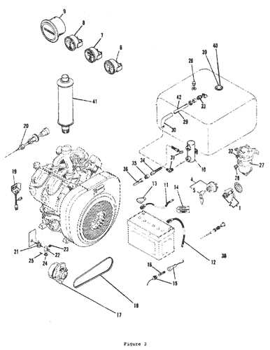
- Leaks: Fluid leakage can indicate worn seals or gaskets.
- Unusual Noises: Grinding or rattling sounds often point to bearing issues.
- Reduced Efficiency: A drop in performance may suggest that filters or other critical components are clogged or failing.
Reading Labels and Annotations
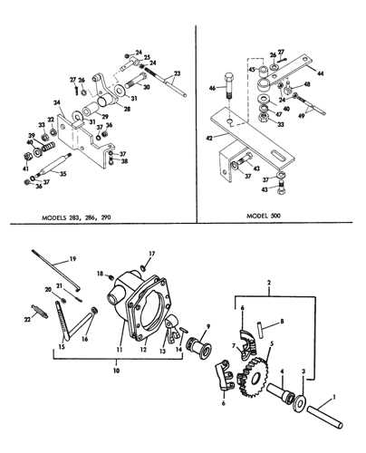
Understanding the information presented on labels and annotations is essential for effective identification and utilization of components in any mechanical system. These markings provide crucial insights into specifications, maintenance requirements, and safety precautions.
Labels often contain vital data, such as model numbers, manufacturing dates, and performance ratings. It is important to familiarize yourself with these elements, as they can significantly influence the selection and replacement of items within a system.
Annotations serve to clarify operational instructions and technical details. They may include symbols and shorthand that are standardized within the industry. Being able to interpret these notations accurately is vital for proper assembly and troubleshooting.
Using the Diagram for Maintenance
Utilizing visual representations of components can significantly enhance the upkeep process of mechanical systems. By having a clear illustration of various elements, operators can better understand the assembly and functionality of each section. This knowledge aids in effective troubleshooting and maintenance, ultimately extending the lifespan of the equipment.
Here are some ways to effectively use the illustration for maintenance tasks:
- Identifying Components: Quickly locate individual elements for inspection or replacement.
- Understanding Relationships: See how parts interact with one another, facilitating easier diagnosis of issues.
- Guiding Repairs: Follow the visual guide during disassembly and reassembly to ensure all pieces are correctly positioned.
When engaging in routine checks or repairs, consider the following steps:
- Examine the visual guide before beginning maintenance to familiarize yourself with the layout.
- Highlight any components that appear worn or damaged based on the reference.
- Maintain a checklist of necessary tools and replacement items identified through the visual representation.
By adopting these practices, users can streamline their maintenance procedures, minimize downtime, and ensure the system operates at optimal efficiency.
Comparing Diagram Variants
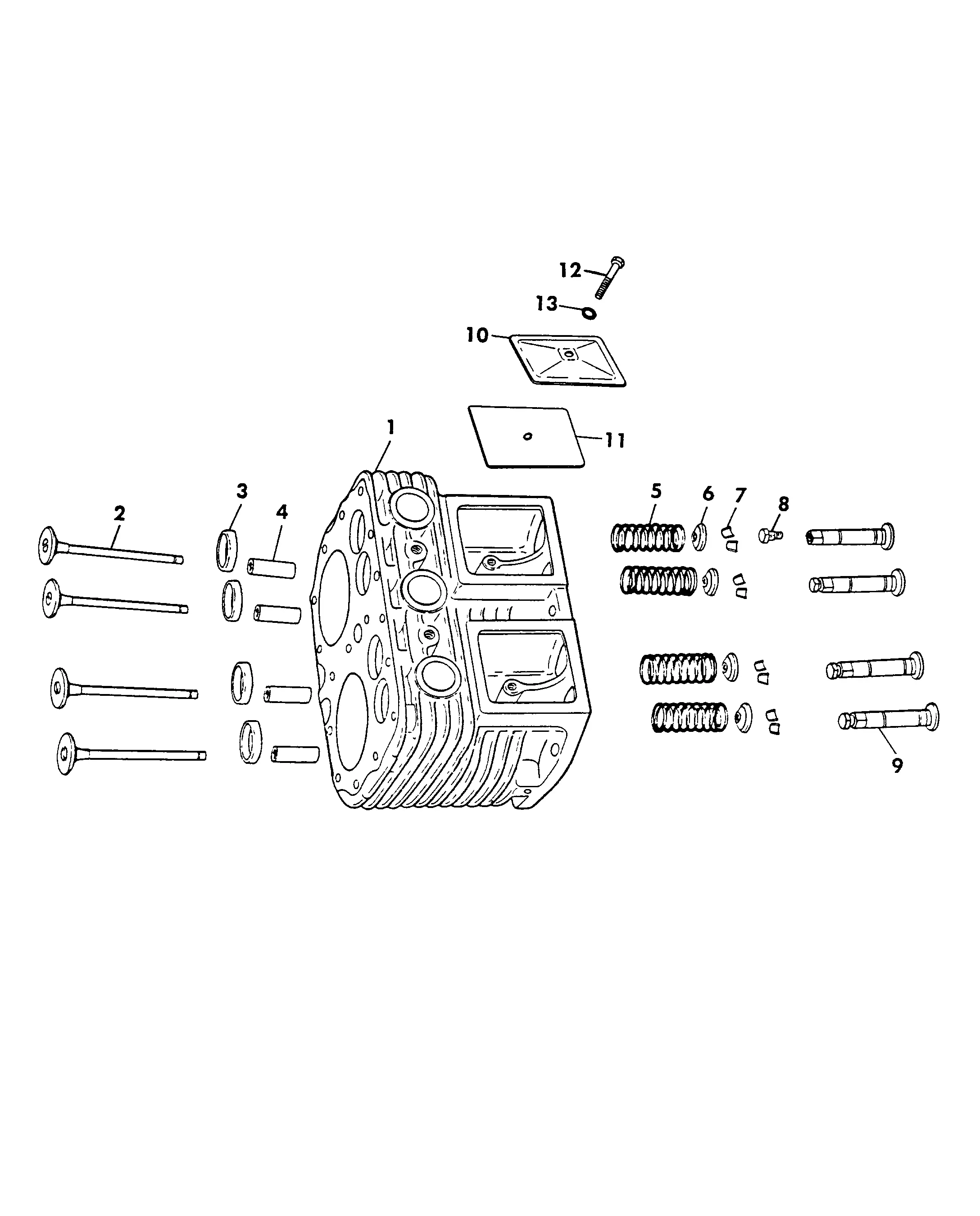
When examining various illustrations of mechanical components, it’s essential to recognize the differences that may exist among them. Each representation serves a unique purpose, highlighting distinct features and functionalities that can aid in understanding the assembly and operation of the machinery.
Variations in these illustrations can arise from different manufacturers, model specifications, or updates in design. For instance, one version may focus on detailed measurements, while another might emphasize the assembly process, offering visual guidance for technicians. These aspects can significantly influence maintenance practices and troubleshooting approaches.
Moreover, analyzing these alternatives provides insight into the evolution of designs over time. As technology advances, modifications in representations reflect improved efficiency and performance, showcasing how components interact and work together seamlessly. By comparing these variants, users can develop a deeper comprehension of the overall system, leading to better operational decisions.
Tools for Better Understanding
To gain a comprehensive grasp of mechanical components, utilizing the right resources is essential. Various instruments and visual aids can significantly enhance your knowledge and facilitate the learning process. Understanding these elements can lead to improved efficiency and effectiveness in various applications.
Visual Aids are invaluable when exploring intricate systems. Diagrams and illustrations can help clarify complex structures, allowing for a better mental picture of how different components interact. By visualizing the connections and functions, learners can more easily assimilate information.
Reference Materials such as manuals and guides provide essential information that can deepen understanding. These resources often include specifications, troubleshooting tips, and maintenance instructions, which are crucial for anyone looking to enhance their expertise.
Hands-On Experience complements theoretical knowledge. Engaging with the components directly allows individuals to apply what they have learned in a practical setting. This experiential learning solidifies understanding and builds confidence in handling various situations.
By combining visual aids, reference materials, and hands-on experience, anyone can significantly improve their comprehension of complex mechanical systems, paving the way for successful application in real-world scenarios.
Common Misinterpretations
Understanding mechanical components can often lead to confusion and misconceptions. Many individuals may misinterpret the relationships between various elements, leading to incorrect conclusions about functionality and maintenance. This section aims to clarify some of the most frequent misunderstandings associated with these components.
- Component Identification: One of the most common errors is mistaking one part for another. This can result in improper assembly or malfunction.
- Functionality Assumptions: Users might assume that all parts serve identical roles, leading to neglect of specific maintenance needs.
- Interchangeability: Believing that similar-looking parts are interchangeable without considering compatibility can lead to significant issues.
- Maintenance Misconceptions: Some may underestimate the importance of regular checks and upkeep, assuming that infrequent inspections suffice.
Addressing these misinterpretations is crucial for effective use and longevity of mechanical systems. Being aware of these common pitfalls can significantly enhance the understanding and performance of the machinery involved.
Interpreting Symbols and Abbreviations
Understanding the symbols and abbreviations commonly found in technical illustrations is crucial for effective maintenance and repair tasks. These graphical representations serve as a universal language, enabling users to grasp complex information quickly and accurately. Familiarity with these notations can enhance the overall comprehension of assembly, functionality, and troubleshooting processes.
Symbols can vary significantly depending on the specific context and application, making it essential to refer to a comprehensive legend or key when working with any technical document. Below is a table that outlines some of the most common symbols and their meanings:
| Symbol | Meaning |
|---|---|
| ⚙️ | Gear or mechanism |
| Tool or maintenance requirement | |
| ⚠️ | Warning or caution |
| Electrical connection | |
| Heat or temperature indicator |
By becoming proficient in reading these symbols and abbreviations, individuals can improve their ability to navigate and interpret technical documents, leading to more efficient and effective maintenance activities.