Understanding Moment Diagrams Through Parts Analysis
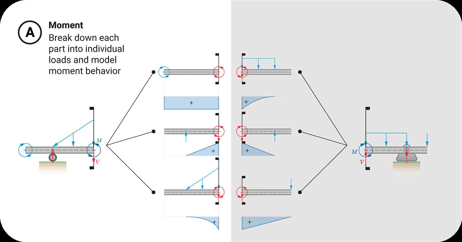
Understanding the response of structures under various loads is essential in engineering. By breaking down complex systems into manageable sections, we can gain valuable insights into their performance. This approach allows for a detailed examination of how forces interact with different elements, leading to more informed design decisions.
In this exploration, we will focus on the methodology of assessing individual sections of a framework, emphasizing the significance of localized analysis. Each segment contributes uniquely to the overall stability and functionality, and recognizing these contributions is crucial for effective structural integrity assessment.
Through systematic evaluation, we can identify critical points of stress and determine the most efficient ways to enhance resilience. By applying this segmented analysis, engineers can ensure that each component operates harmoniously within the larger system, ultimately resulting in safer and more reliable constructions.
Understanding Moment Diagrams
This section delves into the representation of internal forces within structural elements. By visualizing these forces, we can gain insights into how structures respond to applied loads, enabling more informed design decisions. The graphical interpretation allows engineers to assess the behavior of beams and other elements under various conditions, facilitating the identification of critical points that require attention during construction.
Importance of Graphical Representation
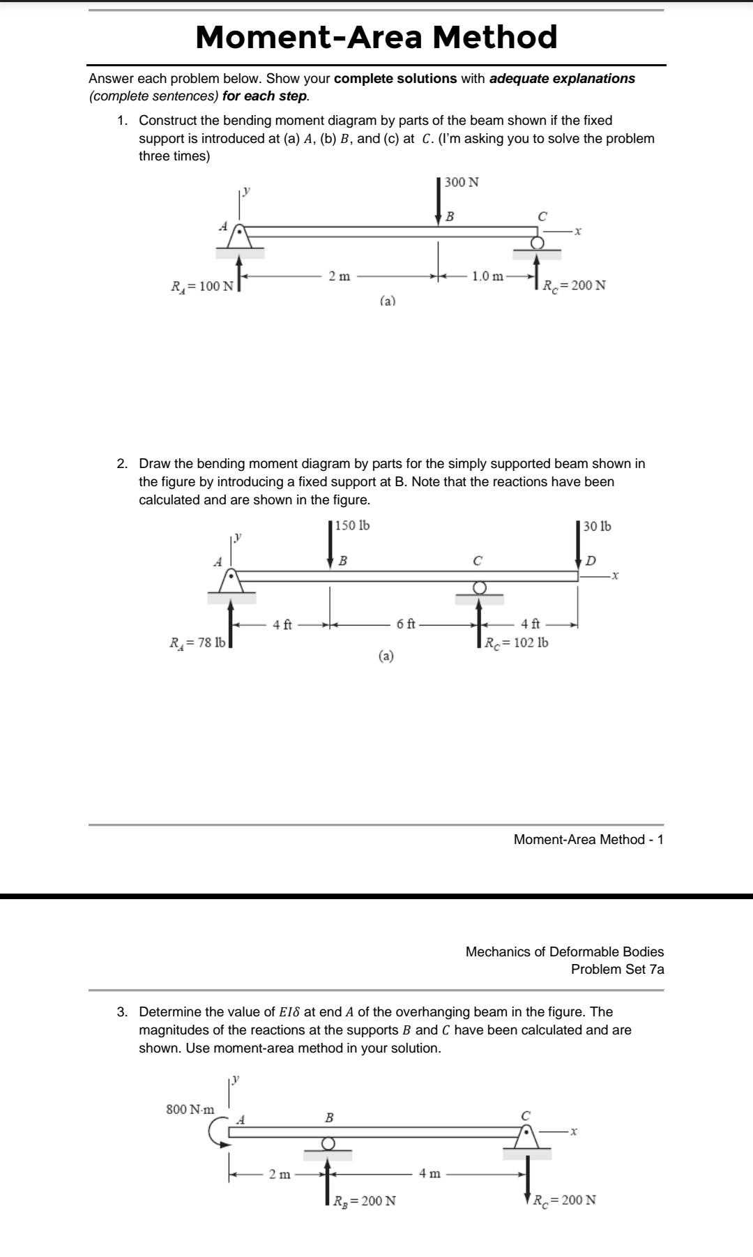
Visual tools play a crucial role in structural analysis. They simplify complex calculations and provide a clear view of how forces interact throughout a structure. Such representations help identify maximum stress locations and ensure that safety margins are maintained during the design phase.
Components of the Visualization
The graphical representation consists of various sections, each corresponding to different loading conditions and support reactions. Understanding these components is vital for analyzing structural integrity and predicting performance under different scenarios.
| Component | Description |
|---|---|
| Support Reactions | Forces exerted by supports that maintain equilibrium. |
| Loading Conditions | Different types of loads applied to the structure, such as point loads and distributed loads. |
| Critical Points | Locations where maximum or minimum values of internal forces occur. |
Importance of Moment Diagrams in Engineering
Visual representations of internal forces play a crucial role in the field of engineering, offering insights that guide structural design and analysis. These tools allow engineers to understand how loads affect materials and ensure that structures can withstand various forces throughout their lifecycle. By providing a clear overview of stress distribution, they facilitate informed decision-making during the design process.
Understanding internal forces helps engineers to identify critical points within a structure, allowing for the optimization of materials and designs. This results in safer and more efficient constructions, reducing the risk of failure and enhancing overall performance. Furthermore, these visual aids are essential for communicating complex concepts to stakeholders, ensuring everyone involved has a clear understanding of the engineering challenges at hand.
| Benefits | Description |
|---|---|
| Safety | Identifies critical stress points to prevent structural failures. |
| Efficiency | Optimizes material usage and design for cost-effective solutions. |
| Clarity | Facilitates communication of complex engineering concepts to various stakeholders. |
In conclusion, these representations are indispensable in engineering, enhancing safety, efficiency, and communication throughout the design process. Their role in analyzing the response of structures to loads ensures that engineers can create robust, reliable, and sustainable designs.
Basic Concepts of Structural Analysis
Understanding the fundamental principles of structural assessment is crucial for engineers and architects. This field encompasses the evaluation of how various forces and loads interact with structures, ensuring safety and functionality. By analyzing these interactions, professionals can design resilient frameworks that withstand environmental challenges while maintaining integrity.
Key Principles of Load Distribution
The behavior of structures under applied forces is governed by several key principles. Load distribution refers to how weight and stress are spread across different components of a structure. Grasping the concepts of equilibrium and stability allows for effective design strategies that can mitigate potential failures. Structures must be assessed for both static and dynamic loads, which vary in intensity and duration, thereby influencing their overall performance.
Importance of Support Reactions
Support reactions play a vital role in maintaining structural stability. These responses occur at the points where structures are anchored or supported, distributing forces throughout the system. Understanding how to calculate and interpret these reactions is essential for ensuring that structures can effectively handle expected stresses. Engineers utilize various analytical techniques to predict these reactions, enabling informed decisions in the design process.
Step-by-Step Construction of Diagrams
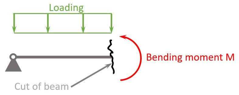
Creating a visual representation of forces and reactions involves a systematic approach to ensure accuracy and clarity. By breaking down the process into manageable stages, one can effectively illustrate the behavior of structures under various loads. This method not only simplifies complex concepts but also enhances understanding through a logical progression of steps.
Initial Setup
The first stage in this process is establishing the framework for the analysis. This includes identifying the structure, the applied loads, and the support conditions. A clear outline helps in visualizing how different elements interact and influence one another.
| Step | Description |
|---|---|
| 1 | Identify the structure and its components. |
| 2 | Determine the types and locations of applied forces. |
| 3 | Define the support reactions based on the conditions. |
Constructing the Representation
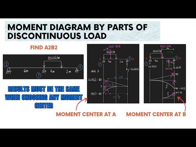
Once the initial setup is complete, the next step involves plotting the identified forces and reactions. This visual construction should be done methodically, taking care to maintain scale and proportion. Each force should be represented accurately to reflect its magnitude and direction.
Common Mistakes in Diagramming Moments
Understanding the nuances of graphical representations in structural analysis is crucial for accurate interpretations. Several common pitfalls can hinder the effectiveness of these visual aids, leading to incorrect conclusions and potentially costly errors in engineering applications.
One frequent error involves overlooking the significance of boundary conditions. Failing to accurately represent constraints can lead to misleading results, as the behavior of the structure may be vastly different from what is depicted. It’s essential to ensure that all relevant support reactions are clearly indicated.
Another common mistake is miscalculating the influence of external loads. Inaccuracies in applying forces can distort the overall picture, making it challenging to derive reliable insights. Careful attention to the magnitude and direction of loads is necessary for a precise representation.
Additionally, neglecting to verify the continuity and transitions between segments often leads to inconsistencies. Smooth transitions are vital for a coherent understanding, as abrupt changes can create confusion and obscure the true behavior of the system.
Lastly, the importance of labeling is frequently underestimated. Clear and precise annotations are essential for conveying critical information. Without proper labels, the intended message can easily be lost, making it difficult for others to interpret the information accurately.
Applications in Beam Design
The analysis and representation of internal forces in structural elements play a crucial role in the design process. Engineers utilize various techniques to ensure that beams can withstand loads while maintaining structural integrity. This section explores the significance of these methods in the realm of beam design.
One of the primary applications is the evaluation of load distribution along the length of the beam. By understanding how forces are transmitted through the structure, engineers can optimize material usage and enhance safety. This analysis aids in determining appropriate dimensions and material types, ensuring that the design meets both aesthetic and functional requirements.
Moreover, visual representations of internal forces assist in identifying potential failure points. By examining the variations in stress along different sections, engineers can make informed decisions about reinforcement needs and structural modifications. This proactive approach minimizes the risk of structural failure, thereby protecting both users and the investment in construction.
Additionally, these techniques facilitate the comparison of different design alternatives. By analyzing various configurations and their corresponding internal stress patterns, engineers can select the most efficient and cost-effective solution. This flexibility in design promotes innovation and the use of advanced materials, contributing to the development of modern construction practices.
In summary, the analysis of internal forces is integral to the effective design of beams. It empowers engineers to create safer, more efficient structures that meet the demands of contemporary engineering challenges.
Effects of Different Load Types
The influence of various loading conditions on structural behavior is a fundamental aspect of engineering analysis. Understanding how different types of forces and pressures interact with materials is crucial for ensuring safety and stability. Each loading scenario can lead to unique responses within a structure, affecting its overall performance.
Point loads are concentrated forces applied at a specific location, which can lead to high stress levels in that area. This type of loading often requires careful consideration of the supporting elements to prevent localized failures.
Distributed loads, in contrast, spread the force over a larger area, resulting in a more uniform distribution of stress. This can enhance the structural integrity, but it may also introduce bending moments that need to be accounted for in design calculations.
Dynamic loads, such as those from wind or seismic activity, introduce time-dependent variations that can lead to significant oscillations in structural response. Engineers must consider these factors to mitigate potential resonance and ensure stability under changing conditions.
Static loads remain constant over time, providing a baseline for assessing structural performance. However, even these can lead to cumulative effects that influence the longevity and durability of materials used in construction.
Ultimately, analyzing the effects of different load types is essential for effective design and construction practices. By comprehensively understanding these influences, engineers can create structures that are not only functional but also resilient to varying forces.
Comparative Analysis of Diagram Techniques
This section explores various methodologies for visualizing internal forces and moments in structural elements. By comparing different approaches, we aim to identify their strengths and weaknesses, providing insights into their applicability in engineering analysis. Understanding these techniques enables professionals to select the most effective method for specific scenarios, enhancing both accuracy and clarity in their work.
| Technique | Advantages | Disadvantages |
|---|---|---|
| Analytical Method | High precision, clear mathematical foundation | Complex calculations, may require advanced knowledge |
| Graphical Representation | Intuitive understanding, visually appealing | Less precise, potential for misinterpretation |
| Numerical Simulation | Handles complex structures, dynamic analysis possible | Resource-intensive, dependent on software proficiency |
| Empirical Approach | Real-world application, practical validation | Limited by data availability, potential for errors in extrapolation |
By assessing these techniques, engineers can better navigate the intricacies of structural analysis, ultimately leading to safer and more efficient designs.
Software Tools for Moment Diagram Creation
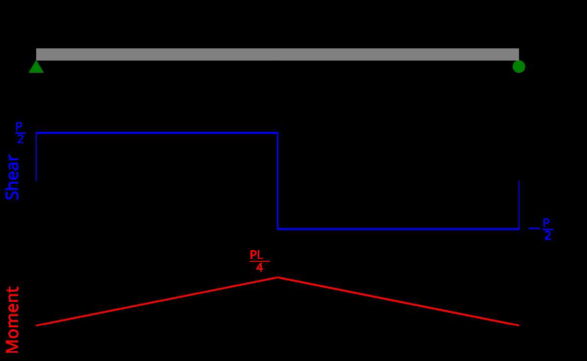
In the realm of structural analysis, specialized software applications play a crucial role in visualizing and calculating internal forces and reactions in various types of frameworks. These tools facilitate the transformation of complex mathematical principles into comprehensible representations, allowing engineers to make informed decisions in their designs.
Key Features of Software Applications
Modern software solutions offer an array of features tailored to streamline the analysis process. Among these, user-friendly interfaces enable seamless navigation, while advanced calculation engines ensure accuracy and reliability. Additionally, many applications support real-time collaboration, allowing multiple users to contribute to a project simultaneously. This collaborative aspect enhances productivity and fosters innovation within teams.
Popular Software Options
Several notable programs stand out in the industry. AutoCAD provides robust tools for drafting and visualization, while MATLAB excels in numerical computing and simulations. SAP2000 and STAAD.Pro are also widely used for their comprehensive capabilities in structural analysis and design. Each of these options brings unique strengths, catering to different needs and preferences in the engineering community.
Real-World Case Studies and Examples
This section explores practical applications of structural analysis through various case studies. By examining real-world scenarios, we can illustrate how theoretical concepts are applied to ensure safety, stability, and efficiency in engineering projects. These examples demonstrate the significance of careful analysis and design in diverse contexts, from bridges to buildings.
Bridge Engineering: A Case Study
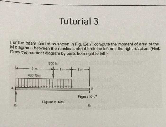
One notable example is the design of a pedestrian bridge in a densely populated urban area. Engineers faced the challenge of optimizing structural integrity while minimizing material use. Through careful calculation of forces and load distribution, the team was able to create a lightweight yet durable structure that seamlessly integrated with its environment.
Building Design: High-Rise Challenges
In the construction of a high-rise building, the analysis of vertical and lateral loads was crucial. The design team implemented advanced modeling techniques to assess how the building would respond to various forces, including wind and seismic activity. This proactive approach not only enhanced the safety of the structure but also provided valuable insights for future projects.
| Project Type | Location | Key Focus | Outcome |
|---|---|---|---|
| Pedestrian Bridge | Urban Center | Load Optimization | Durable and Aesthetic |
| High-Rise Building | Metropolitan Area | Vertical and Lateral Forces | Enhanced Safety |
Future Trends in Structural Analysis
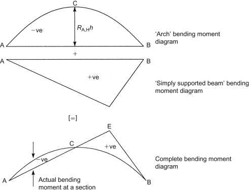
The landscape of structural evaluation is evolving rapidly, influenced by advancements in technology and methodologies. Emerging trends are reshaping how engineers approach design, assessment, and optimization, leading to more efficient and sustainable solutions in construction and infrastructure development.
Integration of Artificial Intelligence
Artificial intelligence is becoming a pivotal tool in the field. By leveraging machine learning algorithms, engineers can analyze vast datasets to predict performance and identify potential weaknesses in structures. This innovative approach not only enhances accuracy but also accelerates the decision-making process, allowing for real-time adjustments during design and construction phases.
Sustainability and Resilience

As the focus on environmental impact intensifies, sustainability is increasingly at the forefront of structural design. Engineers are now tasked with creating resilient systems that can withstand natural disasters and climate change. This trend emphasizes the importance of using eco-friendly materials and innovative techniques to ensure longevity and minimize ecological footprints.
In conclusion, the future of structural evaluation promises exciting developments that prioritize efficiency, safety, and sustainability, paving the way for smarter infrastructure solutions.