Case 1825 Skid Steer Parts Breakdown
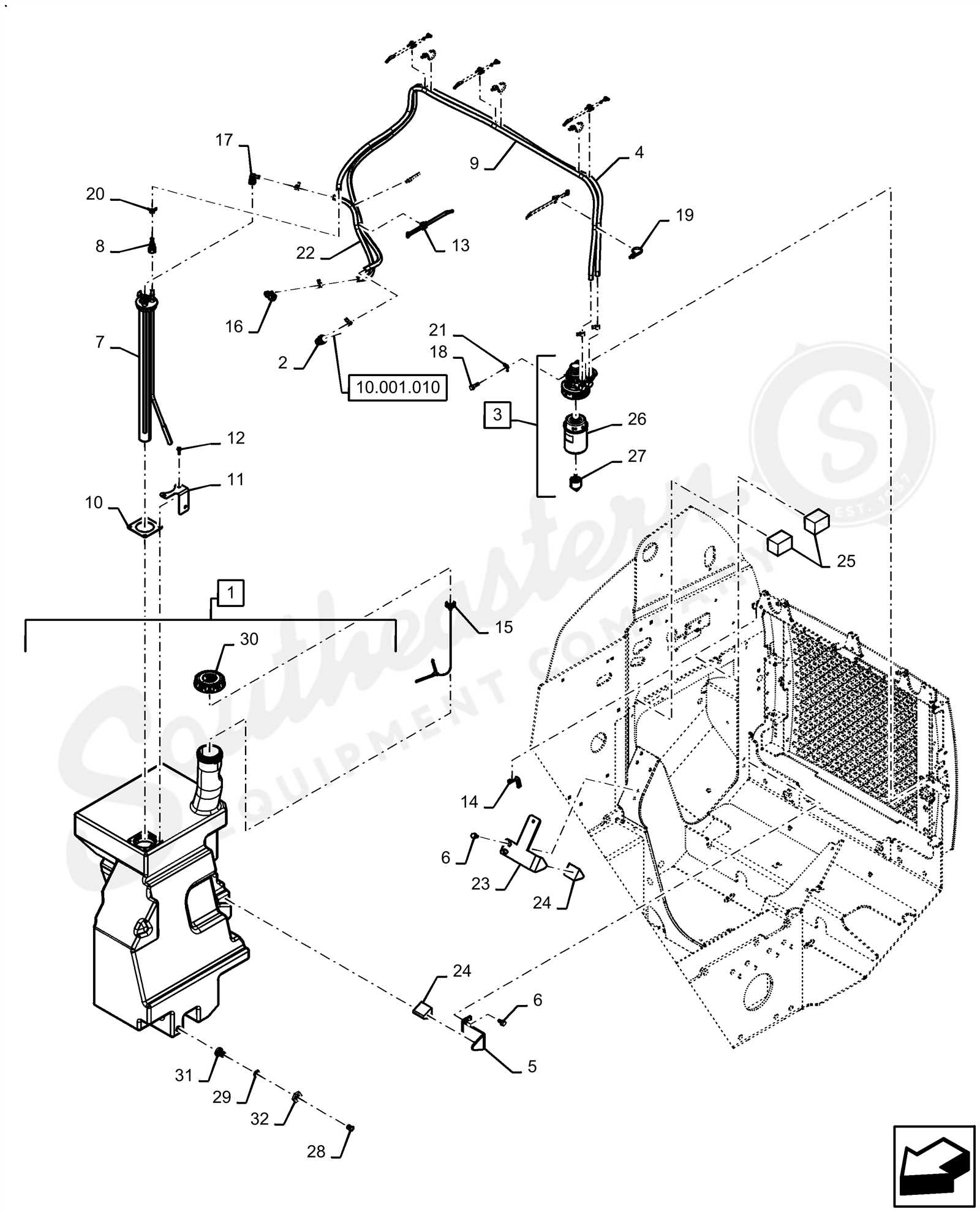
When working with heavy machinery, it is essential to familiarize yourself with the detailed layout of its mechanisms. Proper knowledge of each section ensures not only efficient operation but also easier troubleshooting and maintenance. Every piece of equipment, no matter how compact or powerful, relies on the smooth interaction of its individual elements to function correctly.
In this guide, we will explore how different elements connect within a compact loader to form a cohesive, operational machine. By breaking down the essential mechanical components, you’ll gain a deeper understanding of how each part contributes to the overall performance of the loader. Whether you’re maintaining or upgrading your equipment, understanding these connections can save time and prevent costly mistakes.
Each aspect of the machine’s anatomy plays a pivotal role in ensuring the effective execution of various tasks. By examining these individual elements, you will learn to identify key areas that may require attention, ultimately enhancing both safety and productivity on the job.
Machine Components Overview
The compact loader is made up of numerous essential elements that work together to ensure efficient performance. Each component plays a specific role in maintaining balance, mobility, and power. Understanding how these elements function and interact can help improve the overall performance and longevity of the equipment.
Main Components
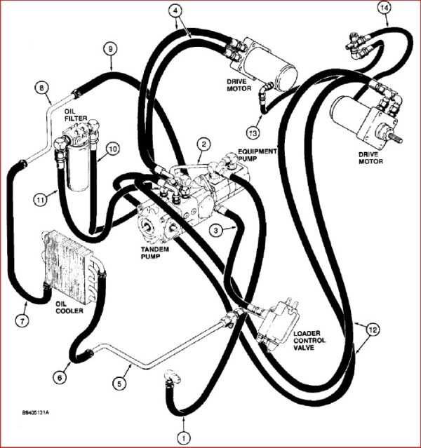
- Engine – Provides the necessary power for all machine operations.
- Hydraulic System – Controls the movement of arms and bucket, crucial for lifting and digging tasks.
- Chassis – Forms the structural base of the machine, giving it stability and strength.
Auxiliary Features
- Control Levers – Allow the operator to navigate and control the machine’s movements.
- Tires – Offer traction and mobility on various surfaces, contributing to the machine’s versatility.
- Cooling System – Prevents the engine from overheating during extended use.
Main Components of the Compact Loader
The mechanical design of this loader includes various crucial elements that contribute to its functionality and efficiency. These core components work together to ensure smooth operation, durability, and versatility, making it suitable for a wide range of tasks. Understanding these key parts is essential for proper maintenance and repair.
Engine and Transmission
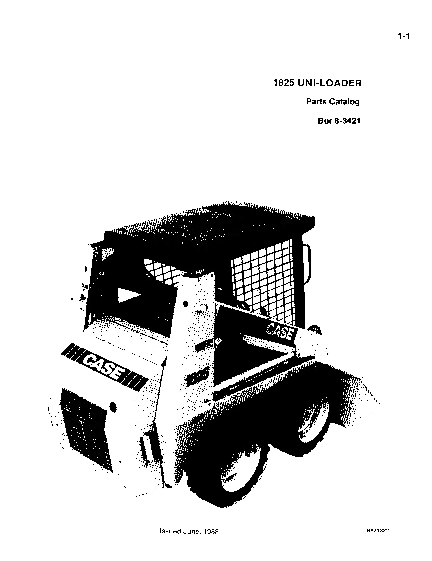
- High-performance engine ensures reliable power delivery.
- Transmission system allows smooth gear shifting and efficient power distribution.
Hydraulic System
- Hydraulic pumps control the movement of the loader’s arms and bucket.
- Valves and cylinders manage fluid flow for precise operation.
- Cooling systems prevent overheating during heavy use.
- Fuel and oil filters protect the engine and hydraulic system from contaminants.
Hydraulic System Breakdown for Compact Loader

The hydraulic mechanism plays a crucial role in powering and controlling various functions of the compact loader. By understanding how the hydraulic components work together, operators and technicians can maintain optimal performance and address potential issues effectively.
Key Components of the Hydraulic System
- Pump: Converts mechanical power into hydraulic energy to drive different loader operations.
- Control Valves: Direct the flow of hydraulic fluid to various cylinders and motors, enabling precision in movement.
- Cylinders: Responsible for converting hydraulic energy back into mechanical force, allowing the loader to lift, tilt, or lower attachments.
Common Hydraulic Issues
- Leaks in hoses or connections, leading to reduced system efficiency.
- Contaminated hydraulic fluid, which can cause wear on internal components.
- Air pockets in the system, resulting in erratic operation or failure to function.
Routine inspection and maintenance of the hydraulic system are vital for ensuring smooth and reliable operation. Addressing any problems promptly helps prevent more significant mechanical failures.
Understanding the Engine Assembly of the 1825 Model
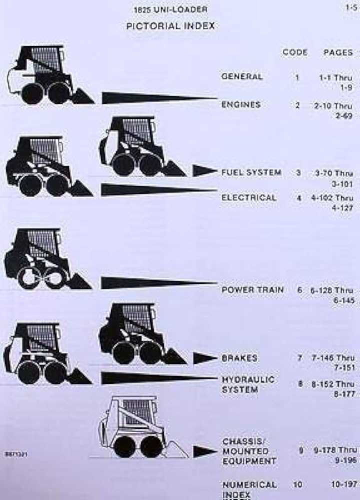
The power unit is the core of any heavy machinery, ensuring that the system operates smoothly under various conditions. A clear grasp of its components is essential for effective maintenance and troubleshooting. This section will explore the different elements that make up the engine structure, providing an overview of its functionality and how each part contributes to overall performance.
Main Components of the Engine
- Cylinder block – houses the essential mechanisms for combustion.
- Pistons – responsible for transferring energy through motion.
- Crankshaft – converts linear motion into rotational force.
- Valves – regulate the flow of air and fuel within the engine.
How the Engine Assembly Works
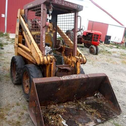
- First, air and fuel are drawn into the combustion chamber.
- The pistons compress the mixture, creating the necessary conditions for ignition.
- Upon ignition, energy is transferred to the crankshaft, which powers the machine.
- Exhaust gases are released through the valves, completing the cycle.
Steering Mechanism Details
The steering system in this model is designed for optimal maneuverability and ease of control. It allows smooth directional changes, which enhances performance during operation. The mechanism is a combination of hydraulics and mechanical components working together to deliver precise movement and handling.
| Component | Description |
|---|---|
| Hydraulic Pumps | Responsible for converting power into hydraulic fluid movement, enabling steering control. |
| Steering Levers | Manual controls that allow the operator to direct the machine smoothly. |
| Drive Motors | Power the wheels for movement, closely tied to the steering for accurate direction changes. |
| Linkage System | Ensures proper transmission of movement between the operator’s input and the wheelbase. |
Guide to the Transmission and Drive System
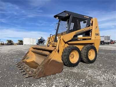
The transmission and drive system is a crucial component that ensures efficient power transfer from the engine to the wheels. This system plays a vital role in the overall performance and maneuverability of the machinery, allowing it to tackle various tasks effectively. Understanding the intricacies of this system can help operators maintain and troubleshoot their equipment more effectively.
Key Components of the Drive System
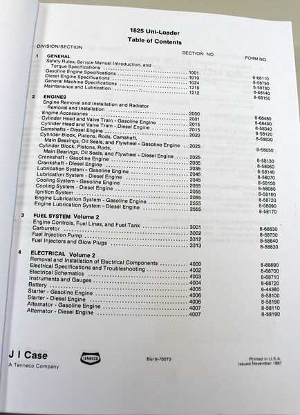
In any effective drive system, several essential elements work together harmoniously. These include the gearbox, drive shafts, and various linkage mechanisms. Each part has a specific function, contributing to the seamless operation of the vehicle.
Maintenance Tips for Optimal Performance
Regular maintenance is crucial for ensuring the longevity and reliability of the transmission and drive system. Operators should routinely check fluid levels, inspect for leaks, and replace worn components as necessary. Keeping these systems in good condition not only enhances performance but also minimizes downtime and repair costs.
Electrical System Components in the 1825 Skid Steer
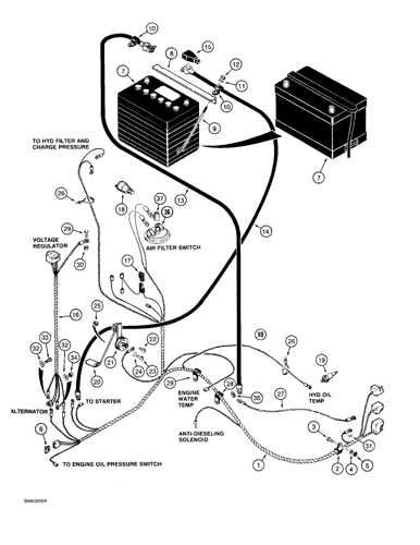
The electrical framework of a compact loader plays a vital role in ensuring its functionality and performance. Understanding the various elements involved is essential for effective maintenance and troubleshooting.
Key components include the battery, which stores electrical energy, and the alternator, responsible for recharging the battery while the engine operates. The starter motor initiates engine ignition, while wiring harnesses distribute power to different systems within the machine. Additionally, fuses protect the electrical circuits from overload, ensuring the safety and reliability of the equipment.
Furthermore, sensors and switches play critical roles in monitoring various functions, such as temperature and pressure levels. These components communicate with the control panel, providing operators with vital information for efficient operation. Regular inspection of these elements helps in preventing electrical failures and prolonging the lifespan of the machinery.
Lift Arm and Bucket Mechanism
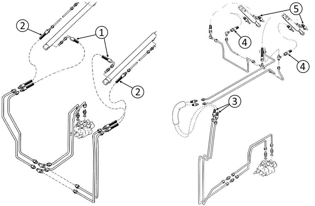
The lift arm and bucket mechanism is crucial for the effective operation of compact construction equipment. This system allows for the lifting, lowering, and tilting of the bucket, enabling the machine to perform various tasks such as loading, digging, and material handling. Understanding its components and functionality is essential for optimal performance and maintenance.
Key Components
This mechanism consists of several vital elements that work together seamlessly. The primary components include the lift arms, hydraulic cylinders, bucket linkage, and the bucket itself. Each part plays a specific role in ensuring smooth and efficient operation.
Functionality Overview
The hydraulic cylinders are responsible for generating the lifting force, which raises and lowers the lift arms. The bucket linkage connects the arms to the bucket, allowing for precise control of the bucket’s position. This coordinated movement facilitates various functions, including excavation and material transport.
| Component | Function |
|---|---|
| Lift Arms | Support and raise the bucket |
| Hydraulic Cylinders | Provide lifting force |
| Bucket Linkage | Connects lift arms to the bucket |
| Bucket | Holds and moves materials |
Cooling System Components in the Loader
The efficiency of a loader’s performance heavily relies on its cooling mechanism, which is essential for maintaining optimal operating temperatures. This section will delve into the various elements that contribute to the effective functioning of the cooling system, ensuring the machinery runs smoothly and efficiently.
| Component | Description |
|---|---|
| Radiator | The primary component responsible for dissipating heat from the engine coolant, allowing for effective temperature regulation. |
| Water Pump | This pump circulates coolant throughout the engine and radiator, ensuring consistent flow and efficient cooling. |
| Thermostat | A vital device that regulates the temperature of the coolant, opening and closing to maintain the optimal operating range. |
| Coolant Reservoir | A tank that holds excess coolant, enabling the system to adjust to fluctuations in temperature and pressure. |
| Cooling Fan | This component enhances airflow through the radiator, particularly during low-speed operation or high-temperature conditions. |
Replacing Worn-Out Parts in Case 1825
Maintaining optimal performance in machinery involves timely replacement of components that show signs of wear. Regularly assessing the condition of essential elements ensures smooth operation and prolongs the lifespan of the equipment. Identifying and addressing issues promptly can prevent further damage and reduce maintenance costs.
Begin by inspecting each component for signs of wear, such as cracks, excessive play, or reduced functionality. Utilize manufacturer recommendations and schematics to locate the specific parts needing replacement. Having the correct tools and replacement items on hand streamlines the process, making it more efficient.
Once the worn components are identified, follow the appropriate disassembly procedures to remove them safely. Take care to document the arrangement of parts during disassembly, as this will aid in the reassembly process. After replacing the worn items, ensure that all connections are secure and that the new components are correctly aligned. Performing a thorough test of the machinery after replacement can confirm that the new parts are functioning as intended.
Maintenance Tips for Case 1825 Parts
Proper upkeep of machinery components is essential for optimal performance and longevity. Regular maintenance practices can prevent wear and tear, ensuring that equipment operates smoothly and efficiently. By adhering to a consistent maintenance routine, operators can significantly reduce the risk of unexpected breakdowns and costly repairs.
First, it is important to conduct routine inspections to identify any signs of wear or damage. Regularly check for loose connections, leaks, and unusual noises, as these can indicate potential issues that need addressing. Keeping a detailed log of maintenance activities can help track the condition of various components over time.
Additionally, ensure that all moving parts are adequately lubricated to minimize friction and enhance performance. Using the correct type of lubricant for specific components is crucial, as this can prevent overheating and prolong their lifespan. Cleaning debris and buildup from surfaces will also contribute to more efficient operation.
Finally, always refer to the manufacturer’s recommendations for replacement schedules of essential components. Adhering to these guidelines will ensure that all elements function correctly and help maintain the overall integrity of the machinery.